Typical circuit and principle of operation of the inverter
The more expensive the welding inverter, the more auxiliary units in its circuit that are involved in the implementation of special functions. But the power converter circuit itself remains virtually unchanged even with expensive equipment. The stages of transformation of mains electric current into welding current are quite easy to trace - at each of the main nodes of the circuit a certain part of the overall process occurs.
From the network cable, through a protective switch, voltage is supplied to a rectifying diode bridge coupled with high-capacity filters. In the diagram, this area is easy to notice; there are impressive-sized “banks” of electrolytic capacitors located here. The rectifier has one task - to “turn” the negative part of the sine wave symmetrically upward, while the capacitors smooth out the ripples, bringing the direction of the current almost to a pure “constant”.
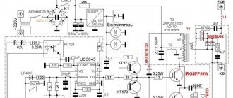
Scheme of operation of the welding inverter
Next in the diagram is the inverter itself. This part is also easy to identify; the largest aluminum radiator is located here. The inverter is built on several high-frequency field-effect transistors or IGBT transistors. Quite often, several power elements are combined in a common housing. The inverter again converts direct current into alternating current, but at the same time its frequency is significantly higher - about 50 kHz. This chain of transformations allows the use of a high-frequency transformer, which is several times smaller and lighter than a conventional one.
The output rectifier removes the voltage from the step-down transformer, because we want to weld with direct current. Thanks to the output filter, the nature of the current changes from a high-frequency pulsating current to an almost straight line. Naturally, in the considered chain of transformations there are many intermediate links: sensors, control and control circuits, but their consideration goes far beyond the scope of amateur radio electronics.
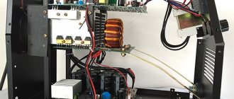
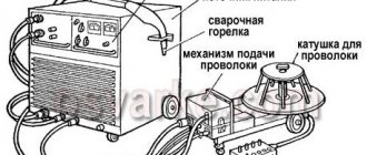
Design of the welding inverter: 1 - filter capacitors; 2 - rectifier (diode assembly); 3 - IGBT transistors; 4 - fan; 5 - step-down transformer; 6 — control board; 7 - radiators; 8 - throttle
Operating principle
Welding inverters are designed so that the output voltage does not depend on the input voltage. This means that the set welding current does not depend on the mains voltage. The use of inverters is convenient when creating an arc, since there is practically no sticking of the electrode.
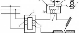
The principle of operation is as follows. Alternating voltage from an industrial network with a frequency of 50 Hz is supplied to the rectifier unit. Converted to a constant value, the signal goes to a power block consisting of IGBT transistors. As a result, due to their key operating mode, a pulse signal with a higher frequency, about 20−60 kHz, is formed at the output of the unit. Further, entering the converter block, the voltage decreases, and the current increases accordingly.
Thus, the required current value is achieved by changing the high frequency signal. This provides an advantage over other types of welding arc power sources. Read tips on working with an inverter here.
Units suitable for modernization
The most important parameter of any welding machine is the current-voltage characteristic (CVC), which ensures stable arc burning at different arc lengths. The correct current-voltage characteristic is created by microprocessor control: the small “brain” of the inverter changes the operating mode of the power switches on the fly and instantly adjusts the parameters of the welding current. Unfortunately, it is impossible to reprogram a budget inverter in any way - the control microcircuits in it are analog, and replacement with digital electronics requires extraordinary knowledge of circuit design.
However, the “skills” of the control circuit are quite enough to level out the “crookedness” of a novice welder who has not yet learned to hold the arc stably. It is much more correct to focus on eliminating some “childhood” diseases, the first of which is severe overheating of electronic components, leading to degradation and destruction of power switches.
The second problem is the use of radioelements of questionable reliability. Eliminating this drawback greatly reduces the likelihood of breakdowns after 2–3 years of operation of the device. Finally, even a novice radio engineer will be quite capable of implementing an indication of the actual welding current to be able to work with special brands of electrodes, as well as carry out a number of other minor improvements.
Improved heat dissipation
The first drawback that plagues the vast majority of inexpensive inverter devices is a poor heat removal system from power switches and rectifier diodes. It is better to begin improvements in this direction by increasing the intensity of forced airflow. As a rule, case fans are installed in welding machines, powered by 12 V service circuits. In “compact” models, forced air cooling may be completely absent, which is certainly nonsense for electrical equipment of this class.
It is enough to simply increase the air flow by installing several of these fans in series. The problem is that the “original” cooler will most likely have to be removed. To operate effectively in a sequential assembly, fans must have an identical shape and number of blades, as well as rotation speed. Assembling identical coolers into a “stack” is extremely simple; just tighten them with a pair of long bolts along diametrically opposite corner holes. Also, do not worry about the power of the service power supply; as a rule, it is enough to install 3–4 fans.
If there is not enough space inside the inverter housing to install fans, you can install one high on the outside. Its installation is simpler because it does not require connection to internal circuits; power is removed from the power button terminals. The fan, of course, must be installed opposite the ventilation louvers, some of which can be cut out to reduce aerodynamic drag. The optimal direction of air flow is towards the exhaust from the housing.
The second way to improve heat dissipation is to replace standard aluminum radiators with more efficient ones. A new radiator should be selected with the largest number of fins as thin as possible, that is, with the largest area of contact with air. It is optimal to use computer CPU cooling radiators for these purposes. The process of replacing radiators is quite simple, just follow a few simple rules:
- If the standard radiator is isolated from the flanges of the radio elements with mica or rubber gaskets, they must be preserved when replacing.
- To improve thermal contact, you need to use silicone thermal paste.
- If the radiator needs to be trimmed to fit into the case, the cut fins must be carefully processed with a file to remove all burrs, otherwise dust will accumulate on them abundantly.
- The radiator must be pressed tightly against the microcircuits, so you first need to mark and drill mounting holes on it; you may need to cut a thread in the body of the aluminum base.
Additionally, we note that there is no point in changing the piece heatsinks of separate keys; only the heat sinks of integrated circuits or several high-power transistors installed in a row are replaced.
Zaitsev welding machine (rectifier + improvements)
Many years ago, when I began to seriously engage in technical creativity, I realized that I could not do this without a welding machine. From then on I began to be interested in them. It seems that the device is not such a complicated one, but there is still no limit to its perfection.
Both experts and practitioners are racking their brains over it: how to make it even simpler, but at the same time better.
Here I am, having made my first welding machine and used it. began to think about how to improve its characteristics. I looked through some available literature on this topic and began to delve into the theory. Over time, I made another device, of course, no worse than the first, but I felt that I could make it better.
In addition, there was a lively and increased interest in everything that related to welding processes and equipment for it. I began not only to read, but also to collect literature and publications on this topic. I am grateful and grateful to all the authors of articles about welding machines that were published in the “Modelist-Constructor” magazine.
I spent a lot of time in my garage making and testing various welding machines. As a result, I came to such a “welder” scheme, which I am happy with and am not ashamed to recommend to others.
I would like to note that welding machines with rectifiers, that is, operating on direct (pulsating) current, are obviously better than “alternating” ones - those that operate without a diode bridge. But the “regulars” also need fine-tuning and tuning. Therefore, I propose proven improvements.
Rice. 1. Schematic diagram of a DC welding machine with control capacitors
First of all, this concerns the inclusion of capacitor C1 in the circuit between the positive and negative wires of the rectified current. The capacitor is electrolytic, with a capacity of 15,000 microns, designed for a voltage of 100 V. It ensures reliable, but at the same time smooth ignition of the arc. If it is not possible to purchase such a capacitor, then you can replace it with a capacitor C1 = 50 μ x 160 V, but in the positive half-cycle current circuit, as indicated in the diagram.
And further. It will be useful to place a paper capacitor of the MBGO or MBGI type with a capacity of 160 microns in the primary circuit. designed for a voltage of 500 V to smooth out power surges.
The step-down transformer and choke can be of various designs; their descriptions and characteristics have been given more than once in the magazine “Modelist-Konstruktor” (for example, No. 11, 1999) and other technical literature. Therefore, their choice remains with the craftsmen.
A.ZAYTSEV, Petrovsk, Saratov region. Modeler-constructor 2006 No. 11.
Increasing duty cycle
The on-time duration in the context of welding inverters is more reasonably called the load duration. This is the part of the ten-minute interval in which the inverter directly performs work; the remaining time it must idle and cool.
For most inexpensive inverters, the actual PV is 40–45% at 20 °C. Replacing radiators and an intensive airflow device can increase this figure to 50–60%, but this is far from the ceiling. A PN of about 70–75% can be achieved by replacing some radioelements:
- The capacitors around the inverter keys must be replaced with elements of the same capacity and type, but designed for a higher voltage (600–700 V);
- Diodes and resistors from the key harness should be replaced with elements with higher power dissipation.
- Rectifier diodes (valves), as well as MOSFETs or IGBT transistors, can be replaced with similar, but more reliable ones.
It is worth talking about replacing the power switches themselves separately. First, you should rewrite the markings on the element body and find a detailed datasheet for a specific element. According to the passport data, choosing an element to replace is quite simple; the key parameters are the limits of the frequency range, operating voltage, the presence of a built-in diode, type of housing and current limit at 100 °C. It is better to calculate the latter yourself (for the high-voltage side, taking into account losses on the transformer) and purchase radioelements with a maximum current reserve of about 20%. Of the manufacturers of this type of electronics, International Rectifier (IR) or STMicroelectronics are considered the most reliable. Despite the rather high price, it is highly recommended to purchase parts from these brands.
Rating of welding inverters
When comparing the highest quality devices, the opinions of authoritative sites and specialized forums were taken into account, where the advantages and disadvantages of products are discussed. First of all, the rating of welding inverters for home among welders was taken into account.
Semi-automatic inverters for welding
- Aurora OVERMAN 180. Characterized by low price and high reliability. The rated current reaches 180 amperes. Energy consumption is no more than 4.7 kW. The design includes a knob for setting the stiffness of the current-voltage characteristic and accelerated broaching. The disadvantage is the lack of a manual wire feeding mode.
- Svarog EASY MIG 160 (N219). Designed for use with 0.8 mm wire. It has a reliable pulling mechanism, the control circuit is ideally adjusted to the input voltage. The downside is that it's a little overpriced.
- Elitech IS 190P. Having an efficiency of 80 percent, it practically does not overheat, operating at a current of 150 amperes. The minimum required voltage for operation is 160 volts. A distinctive feature is ease of use. Disadvantages include the inability to work with one millimeter wire and a short sleeve.
As practice shows, with the same characteristics it is difficult to choose an inverter device for a home or cottage.
The top for each category was formed not only in terms of price and quality, but also in terms of technical characteristics.
Manual arc welding inverters
- FUBAG IR 200. This device has a high current value of 200 amperes. Thanks to this, it makes it possible to cut and weld metals with electrodes up to five millimeters. Their peculiarity is the ability to work even with a network voltage of 150 V. Even a novice welder can cope with any type of welding with such a device due to the presence of the following functions: anti-sticking and arc afterburner. The disadvantages include the duration of work without interruption, associated with a low efficiency of 40 percent.
- Svarog ARC 205 (J96). A reliable device with high mobility due to its weight. Using electrodes with a diameter of three millimeters, it is almost impossible to overheat the device. Can also be used for argon welding. The highest welding current reaches 180 amperes, which does not allow the use of electrodes with a diameter of more than four millimeters. Has an efficiency of 60 percent. Similar to the previous model, it has the following functions: anti-sticking and automatic arc control system. The lower operating voltage range is 185 volts.
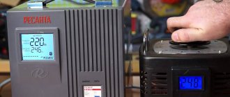
- Resanta SAI-220. The operating current reaches 220 amperes, which allows you to work with electrodes with a diameter of five millimeters. Works reliably at low input voltage. The device is equipped with protection at the input to prevent fires in the wiring. Efficiency reaches 70 percent. The body is made entirely of metal. Excellent value for money and quality. Among the shortcomings are the too easy rotation of the current control knob and a poorly executed ventilation system.
When choosing a device, you need to take into account not only the rating, but it is also advisable to compare reviews on forums. Thanks to such feedback and reviews, a real idea of the selected device is formed. Here are some of them:
I bought a FUBAG IR 200 for small jobs in the garage. ignites the arc well, convenient display. I cut with a four for 20 minutes without overheating. It’s bad that the wires are short, but this is a small thing compared to its reliability.
I work as a professional welder, and I chose Svarog ARC 205 (J96) for myself. Svarog is a pure Chinese, but he is completely satisfied with his work. No problems were found during the year. It is convenient that it is small in size.
I was choosing an inverter for my dacha. I chose the Aurora OVERMAN 180 due to the fact that it works during voltage drops of up to 140 volts. After a month of use it broke. They replaced it under warranty, it turned out to be a manufacturing defect. The replaced device has worked for more than a year without any complaints.
Having listened to the advice, I took the Svarog EASY MIG 160. Turning on the device, I felt like a professional. Ideal welding of aluminum, economical consumption and at the same time the device itself is inexpensive. I didn’t like that the kit didn’t include a holder for MMA, but I’m happy with it.
Winding the output choke
One of the simplest and at the same time most useful additions to a welding inverter will be the winding of an inductive coil that smoothes out the DC ripples that inevitably remain when the pulse transformer is operating. The main specificity of this idea is that the choke is made individually for each individual device, and can also be adjusted over time as electronic components degrade or when the power threshold changes.
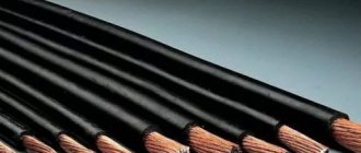
To make a choke you will need nothing at all: an insulated copper conductor with a cross-section of up to 20 mm 2 and a core, preferably made of ferrite. Either a ferrite ring or an armored transformer core is optimally suited as a magnetic core. If the magnetic core is made of sheet steel, it needs to be drilled in two places with an indentation of about 20–25 mm and tightened with rivets in order to be able to cut the gap without any problems.
The choke begins to work starting from one full turn, but the real result is visible starting from 4–5 turns. During testing, turns should be added until the arc begins to stretch noticeably strongly, preventing separation. When it becomes difficult to cook with separation, you need to remove one turn from the coil and connect a 24 V incandescent lamp in parallel with the choke.
Fine-tuning the throttle is done using a plumber's screw clamp, which can be used to reduce the gap in the core, or a wooden wedge, which can be used to increase this gap. It is necessary to ensure that the lamp burns as bright as possible when igniting the arc. It is recommended to manufacture several chokes to operate in ranges up to 100 A, from 100 to 200 A and more than 200 A.
Prerequisites for modernization
Table of required technical characteristics for a welding inverter.
There are several basic prerequisites that force people to move on to modifying a welding transformer. Firstly, if this unit is used in a place where the voltage is unstable. It is designed for stable consumption from 220 to 400 Volts, but this cannot always be achieved. In some cases, the supply voltage may drop far below a critical level. For example, if it drops to 170 Volts, then there is a high probability that the transformer will not work, and, accordingly, the inverter. Devices of this type are not intended for artistic welding. They can rather be used for working with large parts. If you need artistic welding, you will also have to move on to modifying the welding transformer.
Such a device, even at rated voltage values, does not always allow ignition of an arc. The output stage of the transformer does not always produce the required high value. If we talk about lower values, then disaster can happen. That is why, if such problems arise, you can safely move on to revision.
All the work in this case comes down to installing a diode bridge to rectify the current, which will produce a more stable arc at the output and will lead to an increase in the output voltage of the transformer so that ignition can be carried out even with insufficient power. These are very useful solutions that each person can implement on their own.
Welding current indication
Even if a digital current setting indicator is installed on the inverter, it does not show its real value, but a certain service value, scaled for visual display. The deviation from the actual current value can be up to 10%, which is unacceptable when using special brands of electrodes and working with thin parts. You can get the actual value of the welding current by installing an ammeter.
A digital ammeter of the SM3D type will cost around 1 thousand rubles; it can even be neatly built into the inverter housing. The main problem is that measuring such high currents requires a shunt connection. Its cost is in the range of 500–700 rubles for currents of 200–300 A. Please note that the type of shunt must comply with the recommendations of the ammeter manufacturer; as a rule, these are 75 mV inserts with an intrinsic resistance of about 250 μOhm for a measurement limit of 300 A.
Work process
Functionality of the welding inverter.
All the work boils down to adding a jumper to the circuit, consisting of a rectifier bridge with a low-pass filter. The result is a rectifier device, the output of which, at idle, is the value of double the voltage. You can consider in more detail the process of operation of the circuit with a jumper. First, a half-voltage wave enters the first valve, passing through which it enters the filter.
As a result, the rectified voltage is supplied to the transformer winding. The capacitor in the circuit is fully charged. Next, the second half-wave enters the second diode, passing through which it enters the second capacitor. Accordingly, it is also charged to the maximum.
As a result, it turns out that according to the circuit, the voltages from both elements are added together, which leads to a doubling of the value of this parameter at the output. This is exactly what had to be achieved so that the transformer would allow the arc to be ignited without any difficulty. So, we can assume that the first problem is completely solved.
Power supply diagram for an inverter welding machine.
It is also worth noting the fact that the third and fourth rectifiers do not work in any way when there is no load in the circuit, that is, they do not participate in the work process. The modified rectifier bridge circuit allows you to maintain stable output voltage levels, while the standard principle does not allow you to work with maximum arc quality.
This is due to the fact that when the electrode touches the working surface, a sharp discharge of the capacitor occurs, and this leads to a micro-explosion. In such a situation, you should not count on high-quality welding of surfaces. So, the modified bridge will allow you to get a truly amazing result. It allows you to work not only with thick metals, but also to perform jewelry work.
How to increase the power of an arc welder
The power of welding equipment is not an absolutely constant value and depends on various factors. The efficiency of welding installations is influenced by the stability of the supply network and the specifics of production realities, the accuracy of settings, the skill of the welder and even weather conditions. Power in general and welding power in particular is considered to be an obvious performance criterion - the higher this parameter, the more meters of linear seams or the area of welded sections a piece of equipment can process. But the best welding machine, an inverter or its predecessor, is difficult to evaluate in exact figures of power characteristics. Welding is possible in a wide variety of conditions: with an additive or fusion with the base metal; with or without complex edge cutting; under a flux layer, a protective bubble of inert gas or in atmospheric air. The same inverter can work with the obligatory use of specialized equipment, moving parts and technological operations, or do without additional complications. The performance will vary significantly, although the equipment used is the same.
There are not many universal methods to increase the power of your machine, but they are quite effective for various cases of “welding life”. In relation to inverter installations, these include:
- An increase in welding current when setting up the machine, usually with reverse polarity of the connected equipment. A high welding current leads to an increase in the mass of the melt per unit time. It is important to find out how much energy is spent on the penetration depth, and how much leads to the spreading of the metal and an increase in the width of the seams. With small thickness of parts, thoughtless growth of ICB leads to burns and undercuts; for thick workpieces, lack of penetration and other defects in the form of gaps and pores are possible. The recommended penetration rate should be taken into account when increasing ICB.
- An increase in voltage across the arc torch due to a decrease in the potential drop in the anode and cathode regions of the column. By increasing the voltage in the working area of the arc column, the intensity of melting of the electrodes (wire) increases, which automatically increases productivity.
- Improving focusing using attachments, stops, nozzles, etc. No matter how experienced a welder is, tremors of the torch on the surface being welded are inevitable - with the right choice of focusing devices, ineffective dissipation of thermal energy can be significantly reduced.
- Additional preparation. The purity and optimal composition of the inert gas, the quality and thickness of the flux layer, heating of the parts being welded, responsible storage and the same thermal preparation for the electrodes - there are no trifles in increasing welding efficiency.
- Experience and qualifications make it possible to reduce spattering and losses due to scale, change electrodes (spools of wire) less frequently, and calculate in advance the optimal points on the seams for such a technological pause. With increasing skill, large-droplet and jet transfer of the melt becomes easier - and with it, the welding speed increases simultaneously with the quality of the deposited seams and passable joints.
Productivity, power and welding speed are interdependent parameters. They are designed to guarantee high quality of welded joints and seams, optimal operating modes of welding machines and complete safety of welders. The efficiency of welding processes is subordinated to the quality of work, and not vice versa.
Information provided by the online hypermarket Tiberis - www.tiberis.ru
- Author: admin
Rate this article: Share with friends!
Meters: G-Tech/Pro RR & APEXi RSM
Car washing equipment
A few words about the details themselves
Welding inverter choke circuit.
Now it’s worth talking about what details need to be included in the circuit in order to get a very good result. Nothing supernatural will be used. All parts can be purchased without any problems in specialized stores.
As for rectifier diodes, it is best to use the D161 model with standard cooling radiators that are installed on them. You can create a mixed circuit in which rectifiers of the previous brand, as well as model B200, will be used. In this situation, the device turns out to be more compact, since the radiators of each model have different dimensions. It is easier to connect them using a special pin.
Almost any model of these elements can be used as capacitors, but it is better to play it safe and install MBGOs that do not have polarity.
For stable operation of the device, you will have to select the capacity of each element.
To do this, either the random method or mathematics is used. In most cases you can get by with 400 µF.
The current inductor is wound around the transformer core. To do this, a sufficiently large wire must be used. In most cases, you can get by with a cord with a diameter of 10 square millimeters. You need to wind until the window is full. The result should be a space without any gaps. It is worth laying textolite between the halves of the core. It is used as an insulator.
The result is an inverter with stable arc performance and stable ignition. This is what was worth pursuing.
The benefits of working with and purchasing Miller Electric welding equipment
Our company strives to popularize innovative welding equipment that does not require significant investments, both in its acquisition and in its further maintenance. According to the experience of our Customers, who use the equipment not only in the workshop, but also in open areas, the equipment shows exceptional survivability and absence of breakdowns during long-term operation in the harshest conditions. That's why we offer equipment from Miller Electric that can provide quality, performance, reliability and, as a result, maximum cost-effectiveness.
- the most advanced technologies
- excellent quality of welds
- reliability and high performance of equipment
- unpretentiousness to operating conditions and no additional costs
- prompt technical support for all emerging issues
By implementing these principles in each of our proposals or consultations, we offer the optimal solution to the assigned tasks for your welding production. We guarantee safety, excellent quality, reliability and savings. You can buy any welding equipment and original accessories produced by Miller Electric in Moscow at an affordable price from ITS-Engineering LLC. We accept applications by email. You can get professional advice by contacting +7 (495) 660-62-72. If you still have doubts or want to try unique technologies in your production, our company’s specialists are always ready to organize a demonstration of the equipment and tell you in detail about its features live!