The length of the welding cable can vary significantly, since the length of the wire depends on the technical characteristics of the equipment. Often, performers do not have enough length of the cord, which is included in the equipment package, to complete the work. This problem is relevant for beginners and experienced craftsmen.
Therefore, in this article we will look at what length of welding cables is optimal and safe in various cases and when using different types of machines. It is important to know what the welding cable should be like so that the work takes place in comfortable conditions.
Selecting a welding cable by current and length
When choosing an electrical conductor, several criteria should be taken into account: operating conditions, technical characteristics of the welding machine, and others. the maximum current value that the unit is capable of delivering is important It is this parameter that allows you to determine the optimal length of welding cables.
This is quite simple to do: the contractor must familiarize himself with the capabilities of the equipment and choose the best option. That is, the maximum voltage that the device produces must be withstood by the cable. The length of welding cables that is permissible at specific current values and cross-section (mm2) is shown in the table.
| Cable length, m | Current 30-100 A | Current 100-200 A | Current 200-300 A |
| 0-15 | 25 mm2 | 35 mm2 | 50 mm2 |
| 15-30 | 25 mm2 | 50 mm2 | 70 mm2 |
| 30-60 | 35 mm2 | 70 mm2 | 90 mm2 |
Welding cable brands and their characteristics
Since the welding cable experiences increased loads both from the machine and from external factors (building conditions, friction with the ground or concrete, heating, frost), its service life and efficiency depend on the correct choice. First, let’s look into what welding cables exist and what their differences are.
KG
This is the most common type of cable, which stands for “flexible cable”. It is suitable for operation with direct current up to 1000 W or with alternating current up to 600 V and a frequency not exceeding 400 Hz. The wire is used to connect the inverter to a 220 or 380 V network, as well as to connect the electrode holder and ground clamp.
Welding cable KG.
KOG1
Unlike the previous cable, a thinner core diameter is used here, so the cord is especially flexible. As a result, it has a smaller turning radius. This is especially useful when welding in hard-to-reach places, when the welder needs to move his hand with the holder at an unusual angle. This is also practical when working at heights, where it is customary to wrap the cable around your hand (to make it easier to hold) - then the loops will not stick out too much on the sides. Unlike KG, it is designed to pass 220 V with a frequency of 50 Hz.
Welding cable KOG1.
KGN
Such a welding cable with the addition of the letter “H” to the marking means that the material is non-flammable. The insulating shell is made of a heat-resistant coating that can withstand temperatures over 200 degrees. This wire is useful if you have to carry out electric welding/cutting literally in fire conditions (needs of the Ministry of Emergency Situations, repair crews on ships, etc.). In domestic and industrial applications, this is practical when the structure being assembled is large and the welder needs to move around the newly welded areas to continue the work. Then the cable in contact with the heated metal will not melt.
KG-HL
The index of this product contains the letters “ХЛ”, implying permitted use in the cold. For this purpose, special rubber has been added to the composition. It remains flexible at temperatures down to -60 degrees, so it is especially suitable for working in the Far North. If you often have to weld outdoors in winter, then pay attention to products marked KG-HL.
Welding cable KG-HL.
CPEC
This is a type of cable where a spiral tube is used instead of a core. It is designed to pass a wire inside itself to close the circuit and initiate an electric arc. The wire can be either solid or tubular, with flux inside. The cable is used for semi-automatic welding. The price of the cable depends on the internal diameter. But the hollow design helps reduce the service life to 1.5 years. Such an electric main is capable of transmitting a voltage of 42/48 V, regardless of the type of current (AC or DC). It is possible to use a low-voltage line at temperatures down to -10 degrees.
Welding cable KPES.
PIC
A cable with the designation KVS implies the presence of polyvinyl chloride insulation. This sheath is more resistant to abrasion and is suitable in cases where the welder needs to move frequently, dragging the cable along the floor. Insulation will help keep the core from being exposed. The cable can withstand stable voltage transmission of 127-220 V. The temperature range is -40...+40 degrees. But PVC does not have the same flexibility as rubber, so it is not suitable for an electrical holder. Most often, PVC wire is used to connect the welding machine to an outlet.
Welding cable KVS.
KGT
This type of cable can withstand air temperatures up to +85 degrees, so it is optimal for use in hot environments. The coating actively resists fungi and mold, and the cable is suitable for operation in humid, warm conditions.
What is the maximum length that should not exceed
There are practically no standards regarding the length of wires. Some manufacturers post recommendations, and experienced performers give advice. However, it should be noted that each type of welding equipment has its own nuances.
For inverter (220v and 380v)
The permissible length of the welding cable for inverter-type devices is calculated by the formula :
Lmax = Sk / k, where Sk is the maximum cross-section of the copper cable; Lmax – maximum length; k – coefficient: at currents of 200-500 A is equal to 2; for currents less than 200A - the current value must be divided by 100.
The resulting value is the maximum length of the welding cable for the inverter, which is common to the cord with the terminal and electrode holder.
Let's give an example to calculate what is the permissible length of the welding cable for the Resanta 190 inverter. The maximum current value is 190 A. As stated earlier, if the current does not exceed 200 A, then when calculating the coefficient, the current must be divided by 100. This is how it turns out that the coefficient k = 190/100 = 1.9.
When working with an inverter of this type, a cable is used whose cross-sectional area is 16 mm2. That is, Sk = 16. Therefore, the final calculation is as follows: Lmax = 16 / 1.9 = 8.4 meters.
This information will help you easily decide which cable is needed for the welding inverter.
Video
Here’s an additional opinion from a respected YouTube practitioner, Uncle Gena.
[ads-pc-2][ads-mob-2]
Power for semi-automatic
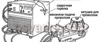
Semi-automatic welding machines are professional equipment and are used mainly in production and industrial conditions. To connect this equipment to the network, cables with a cross-sectional area greater than 35 mm2 are used. The previous table will help you determine which cable is needed for a semi-automatic welding machine. This will allow the contractor to select and purchase a conductor with optimal characteristics.
Fire safety
Important!
According to fire safety regulations, the total length of the welding cable should not exceed 30-40 meters. Using a longer wire results in poor weld quality due to a drop in voltage in the welding circuit. In addition to the inadvisability of using a cord that is too long, it can also lead to equipment failure and harm to the health of the performer.
The length of the cords between the power supply and mobile units should not be more than 10 meters.
How to choose a welding cable
Having understood the labeling of goods, let's move on to practical advice on choosing. The welding cable must match the machine with which it will interact. There are other parameters that are selected based on the upcoming welding tasks.
What should be the core of the welding cable?
The welding cable connected from the device to the holder and ground can be single-core (for example, 1x16). The first number means that in cross-section it has a common core, not divided into two or three isolated lines under a single shell. This design reduces heating and promotes accelerated voltage transfer from the source to the holder.
Single-core welding cable.
Multicore cables are designated 11x30, where the first digit indicates the presence of 11 separate cores. This design is used in industrial installations using voltages of 500 A and higher.
Multicore welding cable.
The core itself can be aluminum or copper. In stores, welding machines are most often equipped with aluminum cables, since they are cheaper. This is enough for a novice welder or rare use of an inverter.
Aluminum welding cable.
Professionals always install copper cables, since their resistivity is 7 times less than that of aluminum. As a result, current losses are reduced. Copper also bends better and heats up less.
Copper welding cable.
A cheap Chinese cable may be called copper, but contain no more than 70% Cu. This is easy to notice by the dull color of the vein in the section. The product is suitable for household needs, but for production it is better to abandon it.
Welding cable cross-section
Inside the metal core there are thin wires, which can be from 30 to 1000. Their total cross-section is selected according to the power of the device and the current used. For example, a cable with a cross-section of 1x6 mm² is designed for a maximum load of 11 kW with a current of 80-100 A. But you should never use the calculated values to the maximum. It is optimal to always divide them by 2. As a result, such a wire is suitable for a power source with a power consumption of 5 kW. As the current strength (A) increases, it is necessary to increase the cross-section of the cable, otherwise it is the same as trying to refuel a car at a gas station through a straw - the narrowed passage will reduce performance.
Compound
The connection of welding cables can be made by hot soldering, welding, crimping or using couplings with subsequent insulation of the connection points. There is also another method, which is the simplest - this is a twist connection. The connection of welding cables when increasing the length is carried out using all of the above methods. The most reliable is welding.
In practice, three welding methods :
- contact;
- gas;
- termite.
The first method is suitable for connecting cores of solid copper or aluminum wires; involves the use of pliers with two carbon electrodes. The energy source is a transformer or inverter. Flux may also be used. The fusion of the ends of the cores is carried out as a result of heating the electrodes.
Gas welding is used to work with single-wire aluminum conductors, the cross-sectional area of which does not exceed 20 mm2. The use of this method for welding copper conductors is unacceptable. The hot gas is an acetylene-oxygen and propane-air mixture. Stranded conductors should be welded in two stages: connecting the conductors into a single whole, and then fusing them together.
For thermite welding, special (thermite) cartridges ATO, A and AT are used.
The connections must be insulated, for example with insulating tape. Thus, the connection of welding cables when increasing the length will be reliable.
Other connection methods are presented in the corresponding article. [ads-pc-3][ads-mob-3]
1x35, 25 mm2, 16 mm2: what do these numbers mean?
The marking of welding cables includes, in addition to letters, also numerical designations, for example, 1X35 or 16 mm2. Let's take a closer look at the first example. In markings of this type, the number “1” indicates the number of conductive cores, and “35” is the cross-section of the conductor, which is measured in mm2. Therefore, it becomes clear that 16 mm2 is also a designation of the cord cross-section. In a similar way, you can determine the number of cores and their cross-section in any conductor. [ads-pc-3][ads-mob-3]
Types
Some performers believe that by cable types, they mean division by the number of cores and wire cross-section. However, this is not an entirely correct point of view. In most cases, we are talking about the fact that conductors are flexible () and especially flexible (COG).
Each type has several varieties , which are intended for use in different climatic conditions: HL - cold-resistant; T – tropical; n – non-combustible insulation. These designations are present in the markings of the conductors, so it will be easy for any performer to identify the specific type. KG and KOG have design features presented in the article “Brands of welding cables”.
