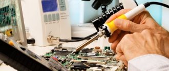
In a short time, inverter welding machines have gained unprecedented popularity among specialists. Despite the reliability of the power supply, repair of a welding inverter may sometimes still be necessary. Diagnosis of a malfunction and replacement of a failed part, if you have some skill, can be done at home. To carry out repairs, you must first familiarize yourself with the design of the device and only then proceed with the repairs.
Common causes of breakdowns
Do-it-yourself repair of welding inverters is possible for the following faults:
- Unstable welding arc. In most cases, such a malfunction is associated with an incorrect choice of the inverter operating mode. To select the optimal current strength, you can follow the rule: 20 to 40 amperes of current should be supplied per 1 millimeter of electrode diameter.
- The appearance of forces when separating the electrode from the metal. A typical malfunction that occurs due to low voltage coming to the electrodes. The simplest way to solve this problem is to clean the contacts of the power supply from oxides and carbon deposits.
- No welding jet. If there is no power when you turn the toggle switch to turn on the device, you should check the voltage in the electrical network.
- Inverter shutdown during prolonged operation. As a rule, such behavior of the inverter can be associated with overheating. The way out is simple: let the device cool down and start working again after 30 minutes.
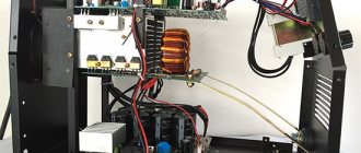
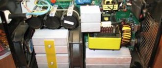
Scheme of an inverter welding machine.
When diagnosing a welding machine, the following faults may be detected:
- arising as a result of incorrect choice of welding mode;
- arising as a result of failure of electronic components of equipment.
In any of the above cases, you can repair the welding inverter yourself.
Most malfunctions of this welding machine unit are associated with the failure of electronic components.
The main types of electronic circuit faults are presented:
- Moisture entering the inverter housing. Oxidation of conductive paths due to moisture ingress can cause a breakdown in contact between the main components of the device.
- Formation of a large amount of dust on the main working elements. Excessive dust contamination of inverter elements can disrupt the natural circulation of air in the housing and lead to overheating of electronic components.
- Selecting the wrong operating mode for the inverter, resulting in overheating of electronic components. Inverter failure due to overheating of electronic components is one of the most common failures.
In addition, the device’s inoperability may be due to the failure of one of the modules.
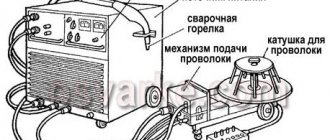
Most inverters use:
- input rectifier;
- output rectifier;
- key control unit;
- cooling system.
The main reasons for the failure of inverters and their manifestations
The main reasons for the failure of welding inverters are violations of the rules of their operation. You can learn about the operating modes and maintenance features of a particular device from its passport; in general, approximately the same list of activities is given:
- daily external inspection of the main unit and cables;
- periodic internal cleaning of the device with compressed air;
- routine inspection, cleaning, pulling and repair of connections of internal power contacts;
- measuring insulation resistance and checking protective grounding circuits.
The main factors that cause inverter malfunction are:
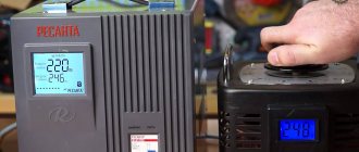
- Sudden changes in input voltage. Its fall leads to instability and termination of the inverter's operation, while a significant excess can cause failure of the elements of the input rectifier.
- Mineral dust. Covers the surfaces of the internal parts of the device and clogs the ribbed surfaces of radiators for cooling diodes and transistors. This leads to a violation of the thermal regime and can cause failure of individual elements.
- Metal dust and fine shavings. It gets inside the inverter through the input fan if work is being done next to it with grinders, grinders, etc. It can cause an internal short circuit.
- Water and high humidity. Causes oxidation of wires and contacts and can lead to a short circuit.
- External mechanical damage. Sometimes they cause failure of controls and internal structural elements on which electronic components are attached.
The following describes the main malfunctions in the operation of inverters and their causes.
Arc instability, metal spatter
If there are significant fluctuations in the input voltage or incorrect operation of the inverter control system, abrupt changes in the welding current occur, which leads to arc instability. In this case, first of all it is necessary to check the network voltage. If it is normal, but the oscillations continue, internal diagnostics of the inverter should be performed.
Spattering of metal during welding is usually a consequence of incorrect selection of welding current. The reason for this may be either a human factor or a malfunction of the current regulator or control system.
Inverter does not turn on
This phenomenon may have several reasons:
- poor contact of the ground cable clamp;
- input voltage too low;
- the input circuit breaker has turned off (the reason for this may be an internal short circuit);
- The thermal protection has tripped.
In the latter case, you need to wait until the device cools down and try to turn it on again. If the protection trips repeatedly, the inverter requires maintenance or repair.
Inverter overheating
The main reason for overheating of the inverter is a violation of thermal conditions due to a large amount of dust in the internal space of the device. Dust acts as thermal insulation, covering the surfaces of components cooled by the air flow, and does not allow fans to operate normally. If there is constant overheating, before talking about diagnostics and repairs, it is necessary to carefully and very carefully clean all internal modules with compressed air. Another reason for overheating of the inverter is non-compliance with the recommended value of the PV parameter (on duration).
Figure 3 - PV parameters
Increased power consumption
Increased power consumption at idle at the standard value of the input voltage of the network is usually associated with a short circuit between the turns of one of the windings of the high-frequency transformer. Externally, such a malfunction looks like burning of the insulation around its live parts and is most often accompanied by a drop in the no-load voltage (sometimes by two to three times). It is not difficult to remove, disassemble and inspect the transformer yourself, but it is better to entrust its repair to someone who is well versed in this.
Electrode sticking to metal
If the electrode sticks during the welding process, most likely this is caused by incorrect selection of technological parameters and poor preparation of the surfaces to be welded. In addition, to prevent this phenomenon, all modern inverters are equipped with an automatic Anti-Stick function. When the value of the welding current corresponds to the diameter of the electrode and the thickness of the metal being welded, and the welding zone is cut and cleaned properly, the cause of sticking (sticking) may be a periodic decrease in voltage both from the electrical network and directly in the welding circuit.
In the first case, it is necessary to stabilize the mains power supply or use an inverter with the ability to operate at reduced voltage. On the welding chain side, the contacts must be periodically cleaned and their reliability checked. In addition, a voltage drop can be caused by the use of cables whose length and cross-section do not meet regulatory requirements.
Inability to adjust current
First of all, we can talk about a malfunction of the indicator that displays the current value. Also, one of the most common reasons is a broken wire, breakdown or internal wear of the potentiometer, which sets the value of the welding current. If all this is in order, then the problem may be a malfunction of the inverter control system. Only an experienced specialist can understand it and perform such repairs.
Spontaneous shutdown
The reasons for sudden shutdowns of the welding inverter can be sudden surges in the supply voltage, a malfunction of the input circuit breaker, and the operation of temperature protection. In the first case, it is necessary to somehow stabilize the input voltage or use a device designed to operate in this range. If the temperature protection is frequently triggered, it is necessary to clean the internal part from dust and check compliance with the manufacturer's recommendations for the duration of continuous operation. You can check the serviceability of the input machine without complex repairs by temporarily connecting a known-good device instead.
General procedure for diagnosing welding inverters
Before repairing the device, you should check the functionality of the cooling system. Cooling radiators clogged with dust remove heat from the power elements much worse, which means the fins should be completely cleaned of dust and other debris.
Repair of inverter welding machines should begin with diagnosing the input rectifier.
To fully check this node you should:
- disassemble the module;
- remove the radiator;
- remove the diode bridge;
- ring the contacts of the diode bridge.
If no problems with the diode bridge are identified, you should move on to the next module - the output rectifier.
Typical inverter faults.
The functionality of the output rectifier is checked using the following algorithm:
- disassemble the module;
- unsolder the diode assemblies;
- ring the diodes.
In addition to diodes, the output rectifier circuit contains radiators that should be installed back after repairing the module.
After examining the output rectifier, you should proceed to diagnosing the key module.
This inverter module consists of:
- four groups of transistors;
- key control boards;
- smoothing rectifiers.
The procedure for examining the key module is as follows:
- Checking transistors. As a rule, a faulty element is clearly visible to the naked eye. If this is not the case, then you should check the sequence of all available transistors with a tester.
- If measurements with a tester do not produce results, you need to diagnose the transistor assemblies using an avometer, measuring the resistance.
- If all components appear to be in good working order, all transistors should be unsoldered one by one. This diagnostic method is suitable if there is a short circuit on the board.
If the transistor converters of the control unit are fully operational, you need to inspect the key control board. To carry out such diagnostics, you should prepare an oscilloscope.
Most inverter problems can be diagnosed by carefully inspecting the electronic components. If defective parts are identified, you should immediately remove them and replace them with similar characteristics.
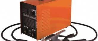
Inverter - what kind of device is it?
To ensure that the connection of metal products is reliable and airtight, special equipment is used. It is called a welding inverter. This device is highly powerful and at the same time economical. It allows you to achieve excellent quality of welding work, as well as significantly reduce the time it takes to complete it.
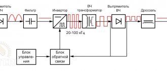
Welding machine diagram
Modern welding inverters are used to connect various materials using consumable electrodes:
- Non-ferrous metals;
- Cast iron;
- Carbon and alloy steels.
The difference between this device and transformer welding machines is its compact dimensions and low weight, which makes it easy to transport the equipment over any distance. It is able to operate stably even during power surges, which avoids frequent repairs of welding inverters. This explains its high popularity among welders.
Welder diagram
Modern inverters are widely used in the following work:
- Construction and installation;
- Repair and restoration.
However, it is no less popular among individuals, allowing them to quickly and efficiently carry out welding work in private households, dachas, and garages.
Repair of inverter power unit
Electrical circuit of a welding inverter.
To repair the inverter power unit, the following tools may be required:
- pliers;
- two soldering irons with a power of 40 and 100 watts;
- screwdrivers of various types;
- wrenches and socket wrenches;
- knife;
- wire cutters;
- tester for electrical network;
- oscilloscope;
- calipers;
- micrometer.
The most typical breakdown of the power unit of a welding inverter is the failure of a powerful transistor. In most cases, a damaged transistor can be identified visually: it has defects, burnouts or deformation. Repairing an inverter if a defective transistor is detected is reduced to replacing it.
There are many cases when a transistor breakdown is only a consequence and not a cause. With this development of events, replacing the transistor assembly may not give a visible effect.
If, after replacing the transistor, the functionality of the device has not been restored, then it makes sense to move on to the next step, namely diagnosing and replacing elements from the diode bridge.
Before repairing the diode bridge, you should check the functionality of all elements. This can be done by alternately measuring the resistance on the legs of the elements. If the resistance between the multimeter probes located on the diode legs is zero or infinity, then this element should be replaced.
New transistors or diodes should be selected from analogs with similar characteristics. As a rule, analogues of the vast majority of models of electronic components are available for sale.
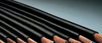
Components of a welding inverter.
When repairing the inverter power unit, you should adhere to the following rules:
- Do not use an electrical appliance with an open insulating casing.
- Diagnostics and replacement of all electronic components must be carried out on a de-energized welding machine.
- It is best to remove accumulated dust and debris from the device using a compressor or a can of compressed air.
- Cleaning the board from sticky traces and used flux should be done using plastic-neutral solvents. It is recommended to use a special brush for cleaning electronic components.
- A working device should be stored in a disconnected state and with the casing completely closed.
Video repair of welding inverters with your own hands
When buying an inverter welding machine for work in a garage or in a country house, the first thought is - wow, now I can cook everything! You do not need a welding diploma; the device is designed for users without special education. Handling welding has become easier and more comfortable. The main thing is to understand the principle of operation and first aid in case of difficulties and breakdowns.