- Mechanical method of connecting reinforcement
- Connecting reinforcement by welding
- Features of tying reinforcing bars
Modern construction technologies provide several ways to connect reinforcement: mechanically using a welding machine, using tie wire or plastic clamps. Let's consider the main features of each of these methods.
Mechanical method of connecting reinforcement
Compared to other technologies, mechanical joining has a number of advantages.
- No overlap is required, which saves metal. The overlap increases the consumption of reinforcement by a quarter.
- Compared to welding, firstly, it is a more productive process, and secondly, it does not require highly qualified workers.
Additional advantages of mechanical butt joints are the strength of the resulting structure and the ability to implement this technology in all weather conditions.
To carry out mechanical joining, a hydraulic press is used as equipment, and steel couplings are used as consumables. You can speed up the mechanical connection of reinforcement bars using couplings with a central partition. The rods are inserted into the coupling, which is compressed using a press. The presence of replaceable dies in the press makes it possible to work with reinforcement of different diameters. The process is carried out by two people.
Connecting reinforcement by welding
The welding method of joining reinforcing bars is a popular technology. There are several options for its implementation.
- Extended seam welding is used for joining horizontal and vertical rods. The reinforcement is welded overlapping or using overlays. Seams can be single- or multi-pass, which is determined by the diameter of the rods.
- Welding with multilayer seams is used mainly for vertically located rods; the electrodes used are coated with calcium fluoride.
- For rods 14-40 mm with pre-assembly in the conductors, a welded connection of the reinforcement is used to form a forced seam. The process takes place using forming devices.
Welding is a convenient type of connecting reinforcing rods, but it has certain disadvantages:
- in the weld area, a change in the microstructure of the metal occurs, causing a decrease in the strength and rigidity of the reinforcing frame;
- the weld seam is weak in bending, which can lead to destruction of the frame even when the concrete mixture vibrates;
- to create foundations, welded joints are recommended only when building a facility on stable types of soil that are not prone to severe subsidence.
The rules for connecting reinforcement in the corners of a strip foundation are set out in SP 52-101-2003 in paragraph 8.3.26; GOST 14098-2014 regulates the basic rules for connecting reinforcement by welding.
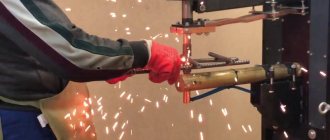
Assembly and welding of reinforcement bars
Reinforcement in concrete structures
should be provided:
- in places where there is a sharp change in the cross-sectional dimensions of elements
; - in places where the height of the walls
(in an area of at least
1 m
); - in concrete walls under and above the openings
of each floor; - in structures
exposed to dynamic loads.
For reinforced concrete
weakly reinforced
elements of a tensile zone
-
the cross-sectional area of longitudinal tensile reinforcement
must be increased by at least
15%
.
Structural reinforcement
is not provided if, according to calculations
taking into account the resistance of the tensile concrete zone
, reinforcement is not required and experience has proven the possibility of transporting and installing such elements without reinforcement.
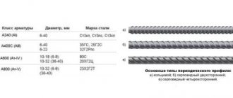
For the foundation, you also need to choose the right reinforcement
ATTENTION! When assembling reinforcement cages
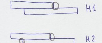
The alignment of the rods
must be strictly observed .
The displacement should not exceed 0.1d
, and the fracture at the junction should not exceed
3°
.
Correspondence of reinforcement location
its design position should be ensured by installing plastic
clamps, washers
made of fine-grained concrete, etc.
READ ALSO: GOST 23279 85 welded reinforcing mesh, characteristics of reinforcing mesh
At intersections of reinforcement in frames
:
- rods of piece reinforcement
up to
d=25 mm
are fastened by spot welding, ligation with knitting wire or using special connecting elements, and
rods d=25 mm and above
- by arc welding; - To obtain cross connections of two or three intersecting rods d=3...40 mm
from steel of class
A-I, A-II, A-III
and wire
d=3...8 mm
of classes
B-I and Bp-I
, spot contact welding is used.
ATTENTION! At least 50% of all intersections
, including the obligatory intersection
of rods with clamps (in the corners)
.
Length of fittings
from the concrete body between the joined rods there must be at least
150 mm
with normal gaps and
100 mm
when using an insert.
With increased gaps between joined rods
It is allowed to use one insert from reinforcement of the same class and diameter.
Minimum distances
in the clearance
between the reinforcement bars
in height and width of the section should:
- ensure the joint operation of reinforcement with concrete and are assigned taking into account the convenience of laying and compacting the concrete mixture;
- for prestressed structures,
compression of concrete
and the dimensions of tensioning equipment (jacks, clamps, etc.) must also be taken into account
In elements
manufactured using bayonet vibrators, free passage between the reinforcing bars of the vibrator tips that compact the concrete mixture must be ensured.
Clear distances between individual bars of longitudinal non-prestressing reinforcement
, as well as between
the longitudinal rods of adjacent flat welded frames,
no less than the largest diameter of the rods
should be taken , as well as:
a) if the rods are being concreted
occupy
a horizontal or inclined
position - not less than:
- for lower reinforcement
- at least
25 mm
; - for upper reinforcement
- at least
30 mm
; - when the lower reinforcement in more than two rows in height,
the distance
between the rods in the horizontal direction
(except for the rods of the two lower rows) must be
at least 50 mm
;
b) if the rods are being concreted
occupy
a vertical position
- at least
50 mm
;
with systematic control of the fractionation of concrete aggregates,
this distance can be reduced
to 35 mm
, but it must be at least
one and a half times the largest size of the coarse aggregate
.
In cramped conditions
It is allowed to place
reinforcement bars in pairs
(without a gap between them).
NOTE: Clear distance between periodic profile bars
taken
according to the nominal diameter
without taking into account protrusions and ribs.
When reinforcing continuous slabs
with welded rolled mesh,
to transfer
lower rods to the upper zone
near intermediate supports .
The distances between the axes of the working rods
in the middle span of the slab and above the support
(at the top) should be no more than
200 mm
for a slab thickness of
up to 150 mm
and no more than
1.5h
for a slab thickness of
over 150 mm
, where
h
is the thickness of the slab.
Periodic profile bars
, as well as
smooth rods
,
in welded frames and meshes
, are made
without hooks
.
The stretched smooth rods of knitted frames and nets
must end
in hooks, tabs or loops
.
For all surfaces of reinforced concrete elements
, near which
longitudinal reinforcement
transverse reinforcement
should also be provided , covering
the outer longitudinal bars
.
In this case, the distances between the transverse rods
at each surface of the element should be
no more than 600 mm
and no more than
twice the width of the edge of the element
.
Transverse reinforcement
It is allowed not to place
bendable elements (
150 mm
or less)
at the edges of thin ribs one longitudinal rod or welded frame
.
When reinforcing eccentrically compressed elements
with flat welded frames, the two outer frames
(located at opposite faces) must be connected to each other to form
a spatial frame
.
To do this, at the edges of the element normal to the plane of the frames
transverse rods
must be placed , welded by contact welding
to the corner longitudinal rods of the frames
, or
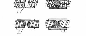
clamps
(Fig. 4) connecting these rods must be installed at the same distances as the transverse
rods of flat frames
.
In reinforcing elements
that work in bending with torsion,
knitted clamps
must be closed with reliable anchoring at the ends.
And with welded frames
, all
transverse rods
in both directions must be welded
to the corner longitudinal rods
, forming
a closed loop
.
, equal strength of connections and clamps
must be ensured .
READ ALSO: Rod and wire reinforcement, characteristics, GOST reinforcement
Protective coatings for fittings
(if they are provided for by the project) are applied in accordance with
SNiP 3.03.01-87
.
The integrity of the protective layer of reinforcement
is checked before concreting, and any defects found are eliminated.
Features of tying reinforcing bars
The knitting method consists of laying overlapping rods and wrapping them with annealed low-carbon steel wire with a diameter of 1.0-1.2 mm. To create a durable structure, it is not recommended to use wire that is covered with rust or has already been used. Instead of wire, manufacturers offer plastic clamps, but at low temperatures they become brittle and burst. The tools used are wire cutters, pliers, crochet hooks or high-performance guns. Guns are effective for connecting reinforcement lengthwise; crochet hooks are convenient in hard-to-reach places.
The advantages of connecting reinforcement without welding are that the structure of the metal is not disturbed, the nodes provide the necessary degree of mobility of the reinforcement, knitting can be carried out both at the construction site and in the workshop.
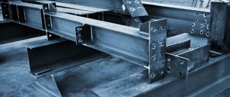
Assembly and welding of installation connections of steel structures
Weldable surfaces of the structure
and
the welder's
must be protected from rain, snow, and wind. At ambient temperatures below -10°C, it is necessary to have an inventory room for heating near the welder’s workplace; at temperatures below -40°C, a warming house must be equipped.
Voltage fluctuations in the electrical current supply network
, to which the welding equipment is connected, should not exceed
±5% of the nominal value
.
Equipment
for automated and manual
multi-station welding
should be powered from a separate feeder.
Types of welded joints
and methods for welding
reinforcement and embedded parts
should be prescribed taking into account the operating conditions of the structure, the weldability of steel, the technical and economic indicators of the connections and the technological capabilities of the manufacturer in accordance with GOST 14098-85.
Welding of structures
when enlarged and in the design position, it should be done after checking the correct assembly.
For welding rods
from steel
of all classes, except AI
, electrodes of grade
UONI 13/55U
or similar are used:
- reinforcement up to d=36 mm
is welded with electrodes
d=4...5 mm
, - fittings d=40 mm and above
- with electrodes
d=5...6 mm
.
Welding is performed without interruption until the joint is completely welded, making sure to fill the craters
.
Then the flange seams are welded. The current strength during manual welding
ranges from
220A
at
d=20 mm
, to
330A
at
d=40 mm
.
Flank weld dimensions
must be:
- height h=0.25d
, but not less than
4 mm
, - width b=0.5d
, but not less than
10 mm
.
The edges of the welded elements
of steel frames
at the locations of the seams and the surfaces adjacent to them must be cleaned to remove rust, grease, paint, dirt, moisture, etc.:
- for manual or mechanized arc welding
- at least
20 mm
; - for automated types of welding
- at least
50 mm
; - as well as the junction of the initial and output strips
.
The number of calcined welding materials at the welder’s workplace should not exceed half-shift requirements. Welding materials should be kept in conditions that prevent them from getting wet.
ATTENTION! Manual and mechanized arc welding of structures
it is permitted to perform without heating at the ambient temperature given in
SNiP 3.03.01-87
.
At lower temperatures, welding
should be carried out with preliminary local heating of the steel to
120...160°C
in a zone
100 mm
on each side of the joint.
Table 1: It is allowed to carry out manual and mechanized arc welding of structures without heating at ambient temperatures.
| p/p | Thickness of welded elements | Minimum permissible ambient temperature when welding structures | ||||
| lattice | sheet volumetric and solid wall | lattice | sheet volumetric and solid wall | lattice and sheet | ||
| of steel | ||||||
| carbon | low-alloy with yield strength, MPa (kgf/mm²) | |||||
| <390 (40) | >390 (40) | |||||
| 1 | 2 | 3 | 4 | 5 | 6 | 7 |
| 1 | <16 mm | -30°С | -30°С | -20°С | -20°С | -15°С |
| 2 | 16mm <25mm | — | — | — | — | 0°C |
| 3 | 16mm <30mm | -30°С | -20°С | -10°С | 0°C | For a thickness of more than 25 mm, local preheating should be carried out regardless of the ambient temperature |
| 4 | 30mm <40mm | -10°С | -10°С | 0°C | 5°C | |
| 5 | >40 mm | 0°C | 0°C | 5°C | 10°C | |
Automated arc welding
Submerged arc is allowed to be produced without heating at the ambient temperature given in Table 2.
Table 2: It is permitted to perform automated submerged arc welding of structures without heating at ambient temperatures.
| p/p | Thickness of the welded element | Minimum permissible ambient temperature when welding steel structures | |
| carbon | low alloy | ||
| 1 | 2 | 3 | 4 |
| 1 | <30 mm | -30°С | -20°С |
| 2 | >30 mm | -20°С | -10°С |
Joint seams
Sheet volumetric and solid-walled structures with a thickness of more than
20 mm
during
manual arc welding
should be performed in ways that ensure a reduction in the cooling rate of the welded joint:
- sectional reverse stage,
- sectional double layer,
- cascade,
- sectional cascade.
With double-sided manual
or mechanized
arc welding
of butt, T and corner joints with full penetration, it is necessary to remove its root from the reverse side to clean, defect-free metal before making a seam.
In case of a forced break in work, mechanized arc or automated submerged arc welding
it is allowed to resume after cleaning the crater and the adjacent end section of the weld with a length of 50...80 mm from slag. This area and the crater must be completely covered with a seam.
READ ALSO: Types of cargo trolleys for warehouses
Surfaces of the structure to be welded
and completed seams of welded joints after completion of welding must be cleaned of slag, splashes and deposits of molten metal.
Quality of potholders
, welded joints of fastenings of assembly and installation devices, determined by external inspection, must not be lower than the quality of the main welded joints.
Defective areas
Weld seams should generally be removed in one of the following ways:
- mechanized cleaning (abrasive tool)
- or mechanized cutting.
All surface burns
The base metal with a welding arc should be cleaned with an abrasive tool
to a depth of 0.5...0.7 mm
.
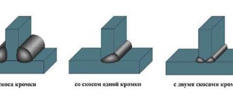
Main types of welds
, structural elements and dimensions of welded joints made of steels made by manual and arc welding are established by GOST 5264-80 and GOST 11534-75.
Main types, structural elements and dimensions of welded joints made of sheet, strip and profile metal used in embedded parts
and
connecting products
of reinforced concrete structures must meet the requirements of GOST 5264 and GOST 8713.
Welded joints
rod reinforcement and reinforcing wire with a diameter of
3 mm or more
, welded connections
of rod reinforcement with rolled
a thickness
of 4 to 30 mm
, performed in the manufacture
of reinforcement
and
embedded products
of reinforced concrete structures, as well as during the installation of prefabricated and construction of monolithic reinforced concrete structures, must meet the requirements of GOST 14098 -91.