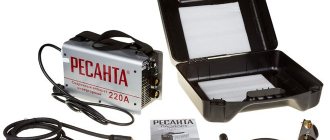
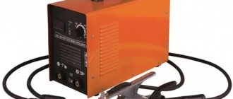
DIY inverter welding machine repair
Repair of welding inverters, despite its complexity, in most cases can be done independently. And if you have a good understanding of the design of such devices and have an idea of what is most likely to fail in them, you can successfully optimize the costs of professional service.
Replacing radio components during repair of a welding inverter
Purpose of the equipment and features of its design
The main purpose of any inverter is to generate direct welding current, which is obtained by rectifying high-frequency alternating current. The use of high-frequency alternating current, converted by means of a special inverter module from rectified mains power, is due to the fact that the strength of such current can be effectively increased to the required value using a compact transformer. It is this principle underlying the operation of the inverter that allows such equipment to have compact dimensions with high efficiency.
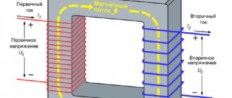
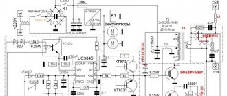
Functional diagram of the welding inverter
The welding inverter circuit, which determines its technical characteristics, includes the following main elements:
- a primary rectifier unit, the basis of which is a diode bridge (the task of such a unit is to rectify alternating current coming from a standard electrical network);
- an inverter unit, the main element of which is a transistor assembly (it is with the help of this unit that the direct current supplied to its input is converted into alternating current, the frequency of which is 50–100 kHz);
- a high-frequency step-down transformer, on which, by lowering the input voltage, the output current significantly increases (thanks to the principle of high-frequency transformation, a current of up to 200–250 A can be generated at the output of such a device);
- output rectifier assembled on the basis of power diodes (the task of this inverter block is to rectify alternating high-frequency current, which is necessary for welding work).
The welding inverter circuit also contains a number of other elements that improve its operation and functionality, but the main ones are those listed above.
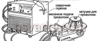
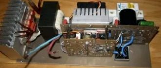
Design of inverter welding machine
Inside the welding inverter there are many elements that interact with each other. The following are attributed to the main modules of the power unit:
- voltage rectifier,
- interference filter,
- converter (aka inverter),
- high-frequency rectifier at the output.
Considering the control board, it uses systems for cooling transistors and filters. Modern inverters have a radiator, rectifier and converter installed. There is a cooler aimed at the step-down transformer.
A step-down transformer
Important ! The control board may have one or more noise filters and capacitors for them.
A current sensor and an integral stabilizer are needed next to the step-down transformer. Advanced high level inverters come with a soft start relay.
Features of maintenance and repair of inverter devices
Repairing an inverter-type welding machine has a number of features, which is explained by the complexity of the design of such a device. Any inverter, unlike other types of welding machines, is electronic, which requires specialists involved in its maintenance and repair to have at least basic radio engineering knowledge, as well as skills in handling various measuring instruments - a voltmeter, digital multimeter, oscilloscope, etc. .
During the process of maintenance and repair, the elements that make up the welding inverter circuit are checked. This includes transistors, diodes, resistors, zener diodes, transformer and choke devices. The peculiarity of the inverter design is that very often during its repair it is impossible or very difficult to determine which element failure caused the malfunction.
A sign of a burnt resistor may be a small deposit on the board, difficult to discern by the inexperienced eye.
In such situations, all details are checked sequentially. To successfully solve such a problem, you must not only be able to use measuring instruments, but also have a fairly good understanding of electronic circuits. If you do not have such skills and knowledge, at least at an initial level, then repairing a welding inverter with your own hands can lead to even more serious damage.
Having really assessed your strengths, knowledge and experience and decided to undertake independent repair of inverter-type equipment, it is important not only to watch a training video on this topic, but also to carefully study the instructions in which manufacturers list the most typical malfunctions of welding inverters, as well as ways to eliminate them.
How to check power keys
IRG4PC50UD keys or its equivalents are installed here. Using a multimeter in diode testing mode, you need to ring the legs of the transistor “E” and “C”; in one direction they should ring, but in the other direction they should not ring; the transistor needs to be discharged (short circuit all legs). On legs “G” and “E” the resistance should be infinite, regardless of polarity.
Next, you need to apply 12 volts DC to the “G” - “+” leg and to the “E” “-”. and ring the legs “C” and “E” they should ring. Next, you need to remove the charge from the transistor (short circuit the legs). Legs “C” and “E” should have infinite resistance. If all these conditions are met, then the transistor is working, and so you need to check all the transistors.
The circuit is fundamentally different from the design of its predecessor - the welding transformer. The basis of the design of previous welding machines was a step-down transformer, which made them large and heavy. Modern welding inverters, thanks to the use of advanced developments in their production, are lightweight and compact devices characterized by wide functionality.
The main element of the electrical circuit of any welding inverter is a pulse converter that generates high-frequency current. It is thanks to this that the use of an inverter makes it possible to easily ignite the welding arc and maintain it in a stable state throughout the welding process. The welding inverter circuit, depending on the model, may have certain features, but the principle of its operation, which will be discussed below, remains unchanged.
Factors leading to failure of the welding inverter
Situations that can cause the inverter to fail or lead to disruptions in its operation can be divided into two main types:
- associated with incorrect choice of welding mode;
- caused by failure of device parts or their incorrect operation.
The method for identifying an inverter malfunction for subsequent repair comes down to sequential execution of technological operations, from the simplest to the most complex. The modes in which such checks are performed and what their essence is are usually specified in the equipment instructions.
Common inverter malfunctions, their causes and solutions
If the recommended actions do not lead to the desired results and the operation of the device is not restored, most often this means that the cause of the malfunction should be sought in the electronic circuit. The reasons for the failure of its blocks and individual elements may be different. Let's list the most common ones.
- Moisture has penetrated into the inside of the device, which can happen if the body of the device is exposed to precipitation.
- Dust has accumulated on the elements of the electronic circuit, which leads to a disruption in their proper cooling. The maximum amount of dust gets into inverters when they are operated in very dusty rooms or on construction sites. To avoid this condition, the inside of the equipment must be cleaned regularly.
- Failure to comply with the on-time (ON) can lead to overheating of the electronic circuit elements of the inverter and, as a consequence, to their failure. This parameter, which must be strictly observed, is indicated in the technical data sheet of the equipment.
Traces of liquid entering the inverter housing
Common faults
The most common faults encountered when operating inverters are the following.
Unstable burning of the welding arc or active spattering of metal
This situation may indicate that the current strength for welding is incorrectly selected. As is known, this parameter is selected depending on the type and diameter of the electrode, as well as on the speed of welding work. If the packaging of the electrodes you are using does not contain recommendations on the optimal current value, you can calculate it using a simple formula: per 1 mm of electrode diameter there should be 20–40 A of welding current. It should also be taken into account that the lower the welding speed, the lower the current should be.
How to repair an inverter device yourself
If after testing it becomes clear that the cause of malfunctions in the operation of the inverter device lies in its internal part, you should disassemble the case and begin to inspect the electronic filling. It is quite possible that the reason lies in poor-quality soldering of the device parts or poorly connected wires.
A careful inspection of electronic circuits will reveal faulty parts that may be darkened, cracked, with a swollen case or have burnt contacts.
Burnt parts on the Fubac IN-160 inverter board (AC-DC regulator, 2NK90 transistor, 47 Ohm resistor)
During repairs, such parts must be desoldered from the boards (it is advisable to use a soldering iron with suction for this), and then replaced with similar ones. If the markings on faulty elements are not readable, then special tables can be used to select them. After replacing faulty parts, it is advisable to test the electronic boards using a tester. This is especially necessary if the inspection did not reveal elements that need to be repaired.
Visual inspection of the electronic circuits of the inverter and their analysis using a tester should begin with the power unit with transistors, since it is this that is the most vulnerable. If the transistors are faulty, then most likely the circuit that drives them (driver) has also failed. The elements that make up such a circuit also need to be checked first.
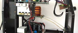
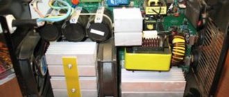
Inverter power unit
After checking the transistor block, all other blocks are checked, for which a tester is also used. The surface of printed circuit boards must be carefully inspected to determine the presence of burnt areas and breaks. If any are found, then you should thoroughly clean such places and solder jumpers on them.
If burnt or torn wires are found in the inverter filling, then during repairs they must be replaced with similar cross-sections. Although the diode bridges of the inverter rectifiers are quite reliable elements, they should also be tested using a tester.
The most complex element of the inverter is the key control board, the serviceability of which determines the performance of the entire device. Such a board is checked using an oscilloscope for the presence of control signals that are supplied to the gate buses of the key block. The final stage of testing and repairing the electronic circuits of the inverter device should be checking the contacts of all available connectors and cleaning them using a regular eraser.
Self-repair of an electronic device such as an inverter is quite complicated. It is almost impossible to learn how to repair this equipment simply by watching a training video; for this you need to have certain knowledge and skills. If you have such knowledge and skills, then watching such a video will give you the opportunity to make up for your lack of experience.
Source
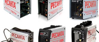
What types of inverters are available on the modern market?
For a certain type of welding, you should choose the right inverter equipment, each type of which has a specific electrical circuit and, accordingly, special technical characteristics and functionality.
Inverters produced by modern manufacturers can be used equally successfully both in industrial enterprises and in everyday life. Developers are constantly improving the electrical circuit diagrams of inverter devices, which allows them to be equipped with new functions and improve their technical characteristics.
The number of connectors and controls on the front panel speaks volumes about the capabilities of the welding inverter
Inverter devices as the main equipment are widely used to perform the following technological operations:
- electric arc welding with consumable and non-consumable electrodes;
- welding using semi-automatic and automatic technologies;
- plasma cutting, etc.
In addition, inverter machines are the most efficient type of equipment used for welding aluminum, stainless steel and other difficult-to-weld metals. Welding inverters, regardless of the features of their electrical circuit, allow you to obtain high-quality, reliable and neat welds made using any technology. At the same time, what is important is that the compact and not too heavy inverter machine, if necessary, can be easily moved at any time to the place where welding work will be performed.
Mobility is one of the advantages of inverter devices
Schematic diagram of a welding inverter: let's look at the details
The circuit of a welding inverter is fundamentally different from the design of its predecessor, the welding transformer. The basis of the design of previous welding machines was a step-down transformer, which made them large and heavy. Modern welding inverters, thanks to the use of advanced developments in their production, are lightweight and compact devices characterized by wide functionality.
Welding inverter without cover
The main element of the electrical circuit of any welding inverter is a pulse converter that generates high-frequency current. It is thanks to this that the use of an inverter makes it possible to easily ignite the welding arc and maintain it in a stable state throughout the welding process. The welding inverter circuit, depending on the model, may have certain features, but the principle of its operation, which will be discussed below, remains unchanged.
What does the design of a welding inverter include?
The welding inverter circuit, which determines its technical characteristics and functionality, includes such mandatory elements as:
- a unit that provides electrical power to the power part of the device (it consists of a rectifier, a capacitive filter and a nonlinear charging circuit);
- power part, made on the basis of a single-cycle converter (this part of the electrical circuit also includes a power transformer, a secondary rectifier and an output choke);
- power supply unit for elements of the low-current part of the electrical circuit of the inverter apparatus;
- PWM controller, which includes a current transformer and a load current sensor;
- a block responsible for thermal protection and control of cooling fans (this block of the circuit diagram includes inverter fans and temperature sensors);
- controls and indications.
Principle of operation
If you disassemble the welding inverter, you can take a closer look at the power transformer. It is the main structural unit and is responsible for the voltage level. The current coming from the source must be reduced.
Welding inverter circuit
Important ! The control board uses capacitors and resistors that are responsible for the conductivity of the electrical flow.
To keep the frequency at 50 hertz, a stabilizer is used. Additional elements include a current rectifier (responsible for ripple) and a choke that stabilizes the output voltage. The device operates in a direct or alternating current circuit. When the voltage is rectified, it is applied to the arc and welding work is allowed.
Welding work
How does a welding inverter work?
The formation of a high current, with the help of which an electric arc is created to melt the edges of the parts being joined and the filler material, is what any welding machine is designed for. For the same purposes, an inverter apparatus is also needed, which allows the generation of welding current with a wide range of characteristics.
In its simplest form, the principle of operation of the inverter looks like this.
- Alternating current with a frequency of 50 Hz from a regular electrical network is supplied to the rectifier, where it is converted into direct current.
- After the rectifier, the direct current is smoothed using a special filter.
- From the filter, direct current flows directly to the inverter, whose task is to convert it again into alternating current, but at a higher frequency.
- After this, using a transformer, the voltage of the alternating high-frequency current is reduced, which makes it possible to increase its strength.
Block diagram of an inverter type welding machine
In order to understand the importance of each element of the electrical circuit diagram of an inverter device, it is worth considering its operation in more detail.
Welding machine diagrams
When considering welding equipment, the electrical and circuit diagrams are studied. If we look at the concepts, it is noticeable that they carry different messages. The information content and the construction model are taken into account. An electrical diagram is a document that communicates the important parts of a piece of equipment. The main task is to show the path of electrical energy through the equipment.
You may be interested in Voltage measurement
Electrical diagram
The components interact with each other and this can be seen in the diagram. Special designations are used for each individual component. When drawing up electrical diagrams, structure as well as functionality is taken into account.
Important ! All standards are specified in GOST 2.702-75.
The circuit diagram is also of the electrical type, but has other tasks. The document is a drawing that also shows the components of the unit. The difference is that the electrical circuit diagram shows the electromagnetic connections. In fact, they don't look as detailed as functional electrical diagrams. If you look at the drawing, only the main components are displayed.
Schematic diagram
Electric
The standard electrical circuit of an inverter welding machine includes powerful transistors with a frequency of 50 Hertz. They operate in a direct current circuit. Power is supplied to the rectifier to ensure a stable output voltage.
Rectifier on the diagram
Important information ! To prevent the frequency from jumping, a diode bridge is used. The element works in tandem with a filter capacitor.
Bridges vary in power and generate high temperatures. To cool them, fans and radiators are used. Filter capacitors require a fuse that will protect the component in the event of a short circuit.
Circuit closures
The diagram also shows an electromagnetic filter, which is responsible for current compatibility. The voltage is supplied from the rectifier; the presented unit is responsible for high-frequency interference. In the case of transformers, the problem is relevant. There are device circuits that include two powerful transistors, which are used with separate radiators.
The transformer is installed at high frequency, it ensures fast voltage conversion. Its switching occurs on the winding, so the maximum voltage in devices of this type reaches 340 volts. To create a low current level at high voltage, a primary winding is needed. For inverters, the parameter is 120 amperes.
Winding switching
Interesting ! High-speed diodes that are installed with the cathode can only be assumed to be connected to the rectifiers.
The design of the elements is simple and can be activated on command. They are responsible for opening and closing the bridge. The main function is again related to the protection of the unit. Immediately after connecting the circuit to the power source, the circuit uses capacitors. They begin to charge, the current level increases to a maximum. The main load is supplied to the bridges, so the charge level is limited.
You may be interested in this How to use the DT-182 multimeter
Capacitors in the diagram
Fundamental
The circuit diagram is designed in such a way that the voltage goes from the rectifier to the inverter and is supplied to the transformer. Next, the current passes through the secondary rectifier and exits through the inductor directly to the electrode.
Secondary rectifier
Plus, from the secondary rectifier the current flows according to the circuit diagram to the feedback unit. It is interconnected with the control unit. From the feedback unit, the signal can go directly to the inverter.
The electrical circuit diagram of a welding inverter is discussed above. The principle of operation and features of the models have been studied. When evaluating units, technical characteristics, advantages, disadvantages, purpose and scope of use are taken into account.
Processes occurring in the electrical circuit of a welding inverter
The circuit of an inverter-type welding machine allows you to increase the current frequency from the standard 50 Hz to 60–80 kHz. Due to the fact that high-frequency current is subject to regulation at the output of such a device, compact transformers can be effectively used for this. An increase in the frequency of the current occurs in that part of the inverter electrical circuit where the circuit with powerful power transistors is located. As you know, only direct current is supplied to transistors, which is why a rectifier is needed at the input of the device.
Schematic diagram of the factory welding inverter "Resanta" (click to enlarge)
Inverter circuit from the German manufacturer FUBAG with a number of additional functions (click to enlarge)
An example of a circuit diagram of a welding inverter for self-production (click to enlarge)
The electrical circuit diagram of the inverter device consists of two main parts: the power section and the control circuit. The first element of the power section of the circuit is a diode bridge. The task of such a bridge is precisely to convert alternating current into direct current.
In the direct current converted from alternating current in the diode bridge, pulses may occur that need to be smoothed out. To do this, a filter consisting of capacitors of predominantly electrolytic type is installed after the diode bridge. It is important to know that the voltage that comes out of the diode bridge is approximately 1.4 times greater than its value at the input. When converting AC to DC, rectifier diodes become very hot, which can seriously affect their performance.
Components of a welding inverter using the example of a homemade machine
To protect them, as well as other elements of the rectifier from overheating, radiators are used in this part of the electrical circuit. In addition, a thermal fuse is installed on the diode bridge itself, the task of which is to turn off the power supply if the diode bridge has heated up to a temperature exceeding 80–90 degrees.
Features of the electrical circuit diagram of the welding machine
The inverter, the circuit diagram of which is based on the action of a block of high-frequency transistors (from 55 to 75 kHz), provides for the process of switching the high-power input current coming from the diode bridge.
Scheme of operation of a welding inverter.
The element simultaneously serves to rectify the input voltage. After equalization, filter capacitors can be used to obtain direct current at a voltage of more than 220 V.
The output of the initial stage is associated with the presence of a primary mains voltage rectifier (220 V) with an alternating current frequency of 50 Hz. This source is assembled on the basis of a diode bridge, and the capacitor serves as a simple filter. Current limitation after turning on the device is due to the presence of a nonlinear charging circuit. Its main elements are a shunt thyristor and a current-limiting resistor.
In general, the electrical circuit of an inverter welding machine is associated with the function of a power source that provides operation to the transistor unit of the IIST. This unit operates at a frequency of 60-80 kHz, so you will need a step-down transformer operating at the required frequencies. This feature allows us to produce welding inverters of smaller sizes than transformer machines.
With the smallest dimensions of a modern IIST, in contrast to a transformer apparatus, the power of the device has a constant level. An important step is solving the problem associated with choosing the necessary technology that optimizes the operation of the power unit. It is represented as a constituent element of the electrical circuit diagram of any professional inverter. The power section can be constructed based on a topology that involves the use of a bridge converter, a single-cycle forward bridge and a half-bridge converter.
Description of the operating principle of the welding inverter circuit
The schematic diagram of a welding inverter can be traced based on the order in which the device performs actions. Initially, the IIST welding device connected to the network receives alternating current with a voltage of 220 V, rectification of which occurs if there is a diode bridge in the circuit. To eliminate unnecessary interference in order to protect a high-quality capacitor, special noise filters are installed, which are an obstacle.
Then the current is equalized in the presence of a capacitor and flows to the transistor unit. A current passing through the capacitors has a voltage higher than that at the output of the diode bridges. A step-down transformer has a winding where there must be a frequency at which direct current flows, several times higher than its original value. As a result, the output produces a high-frequency alternating welding current.
Next, the current passes through the circuit of a step-down high-frequency transformer, which has a secondary winding with a large cross-section. In this case, different types of winding materials can be used. The transformer reduces the current to a voltage level of 50-70 V. At the same time, the welding current increases, which exceeds 130 A.
Operating principle of the output diode
If the assembly is homemade, then use a transformer with a secondary winding made using copper (thickness - 0.3, width - 40 mm). The conditions of this approach are to displace high-frequency current onto the surface of conductors, the core of which is not involved, so the device heats up. Next, the resulting current is rectified by the output diodes.
Inverter protection and control elements
Several elements in its circuit diagram allow you to avoid the influence of negative factors on the operation of the inverter.
To ensure that transistors that convert direct current into alternating current do not burn out during their operation, special damping (RC) circuits are used. All electrical circuit blocks that operate under heavy load and become very hot are not only provided with forced cooling, but are also connected to temperature sensors that turn off their power if their heating temperature exceeds a critical value.
Radiators and cooling fans take up significant space inside the inverter
Due to the fact that the filter capacitors, after being charged, can produce a high current, which can burn the inverter transistors, the device must be provided with a smooth start. For this purpose, stabilizers are used.
The circuit of any inverter has a PWM controller, which is responsible for controlling all elements of its electrical circuit. From the PWM controller, electrical signals are sent to a field-effect transistor, and from it to an isolation transformer, which simultaneously has two output windings. The PWM controller, through other elements of the electrical circuit, also supplies control signals to the power diodes and power transistors of the inverter unit. In order for the controller to effectively control all elements of the inverter's electrical circuit, it is also necessary to supply electrical signals to it.
To generate such signals, an operational amplifier is used, the input of which is supplied with the output current generated in the inverter. If the values of the latter diverge from the specified parameters, the operational amplifier generates a control signal to the controller. In addition, the operational amplifier receives signals from all protective circuits. This is necessary so that he can disconnect the inverter from the power supply at the moment when a critical situation arises in its electrical circuit.
Elements of the electrical circuit of welding inverters
The electrical circuit diagram of an inverter welding machine involves a combination of several elements that are interconnected. The main ones can be called:
- The block responsible for supplying energy to the power section. This element is represented by a combination of several devices that are capable of changing current parameters to the required values. Typically, a capacitive filter and a rectifier are included.
- The device includes a power transformer. The power supply of the welding inverter also includes a 4n90 transistor.
- A separate element is responsible for powering the low-current part of the structure.
- To control the main parameters, a PWM controller is installed. It is represented by a combination of a load current sensor and a transformer.
- A separate block is responsible for protecting the structure from heat. When electrical current passes, some components may become very hot. Therefore, an additional cooling module is installed, represented by a fan and a temperature sensor.
- Control units that allow you to set basic parameters, as well as display elements.
The diode bridge equipment for the welding machine is manufactured and installed taking into account the power of the device and some other points. Each device has its own characteristics, which we will consider in detail below.
Advantages and disadvantages of inverter-type welding machines
Inverter welding machines, which replaced the usual transformers, have a number of significant advantages.
- Thanks to a completely different approach to the formation and regulation of welding current, the weight of such devices is only 5–12 kg, while welding transformers weigh 18–35 kg.
- Inverters have very high efficiency (about 90%). This is explained by the fact that they spend significantly less excess energy on heating the components. Welding transformers, unlike inverter devices, get very hot.
- Due to such high efficiency, inverters consume 2 times less electrical energy than conventional transformers for welding.
- The high versatility of inverter machines is explained by the ability to regulate the welding current over a wide range with their help. Thanks to this, the same device can be used for welding parts made of different metals, as well as for welding using different technologies.
- Most modern inverter models are equipped with options that minimize the impact of welder errors on the technological process. Such options, in particular, include “Anti-stick” and “Arc Force” (fast ignition).
- Exceptional stability of the voltage supplied to the welding arc is ensured by the automatic elements of the inverter electrical circuit. In this case, automation not only takes into account and smoothes out differences in input voltage, but also corrects even such interference as the attenuation of the welding arc due to strong wind.
- Welding using inverter equipment can be performed with any type of electrode.
- Some models of modern welding inverters have a programming function, which allows you to accurately and quickly configure their modes when performing a certain type of work.
Like any complex technical devices, welding inverters have a number of disadvantages that you also need to be aware of.
- Inverters are highly expensive, 20–50% higher than the cost of conventional welding transformers.
- The most vulnerable and often failing elements of inverter devices are transistors, the cost of which can be up to 60% of the price of the entire device. Accordingly, repairing a welding inverter is quite an expensive undertaking.
- Due to the complexity of their electrical circuitry, inverters are not recommended for use in bad weather conditions and at low temperatures, which seriously limits their scope of application. In order to use such a device in field conditions, it is necessary to prepare a special closed and heated area.
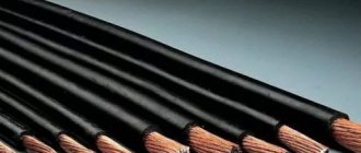
When welding work performed using an inverter, long wires cannot be used, as they induce interference that negatively affects the operation of the device. For this reason, the wires for inverters are made quite short (about 2 meters), which makes welding work somewhat inconvenient.
Source
Advantages and disadvantages
It is important to attribute the following to the strengths of the equipment:
- high efficiency,
- significant power density,
- assortment in stock,
- scope of application.
The disadvantages are also familiar to everyone, we are talking about the high cost of products. The units do not have a long service life. When the electronic board burns out, it is impossible to do anything.
You may be interested in this Checking the microcircuit for serviceability
Electronic board
The problem lies in the insecurity of the case. The workplace is usually full of dust and dirt. All this settles on the internal elements of the structure and a failure occurs.