Home / Electrodes
Back
Reading time: 2 min
0
2643
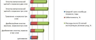
Carbon electrode welding technology is quite rare. This is due to the narrow specification of the carbon filler material. Due to its structure, it does not melt under high temperatures.
This limits its use to welding non-ferrous metals and cast iron. However, in addition to a short list of welding operations, carbon filler material can be used for another type of processing - gouging.
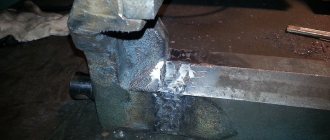
Gouging is a technique for cutting metal surfaces. With this technique, cutting is carried out at partial depth of the part's blade.
This article will look in detail at both types of metal processing using carbon electrodes: welding and gouging.
- General information about carbon welding
- Description of technology
- General information about carbon gouging
- Description of technology
- Conclusion
General information about carbon welding
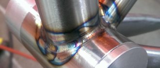
This type of welding is used quite rarely. The structure of the base material is not suitable for welding most metals. However, there are alloys with which it performs well.
These are non-ferrous metals, low-carbon steel or cast iron, the thickness of which does not exceed 3 mm. And also when soldering copper wires.
The key indicator of this material is that it does not melt when exposed to high temperatures. Only melting and evaporation of the copper coating on the surface of the filler material occurs.
Due to this structure, mixing of the filler material with the metal of the part does not occur. This results in minimal rod consumption, and for welders working with consumable type – unusual process characteristics.
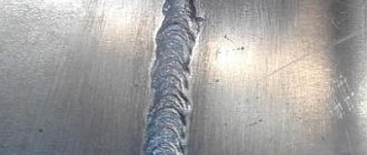
Welding metal surfaces when using non-consumable filler materials occurs by mixing the metal of the parts themselves. Under the influence of high temperatures, the edges of the part melt.
Molten metal fills the weld joint, forming a seam web.
If the size of the gap between the parts does not allow the formation of a reliable seam only by mixing the base metals, filler wire is used for the connection.
How to weld and gouge with carbon electrodes at home yourself
Carbon electrode welding technology is quite rare.
This is due to the narrow specification of the carbon filler material. Due to its structure, it does not melt under high temperatures. This limits its use to welding non-ferrous metals and cast iron. However, in addition to a short list of welding operations, carbon filler material can be used for another type of processing - gouging.
Gouging is a technique for cutting metal surfaces. With this technique, cutting is carried out at partial depth of the part's blade.
This article will look in detail at both types of metal processing using carbon electrodes: welding and gouging.
Description of technology
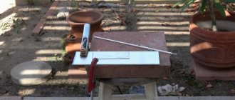
At the beginning of work (both before welding and before gouging), preparation is always carried out. It includes cleaning the welding zone of the surface of the part. Cleaning is carried out with sandpaper, a grinding machine or a file.
All pockets of corrosion, inclusions of foreign materials, dirt, and unevenness are removed. After this, the surface is treated with a degreasing liquid. The quality of the welding joint will depend on the quality of the stripping.
The current level is set depending on the diameter of the electrode. With a size of 4 mm, the current should reach 150-200 Amperes. If the size of the rod is larger, the current strength increases, if smaller, it decreases.
For stability of the arc, it is worth setting up a constant type of current. The polarity is set to negative. This will also reduce material consumption.
To improve the density of the seam and stabilize the arc during gouging and welding, flux is used. They exist in several types: powder, paste, liquid. You can use any, but for use at home, a paste or liquid form is more suitable.
For best effect, the flux must include ionizing substances. The flux itself is applied to the welding surface and distributed in a thin, uniform layer.
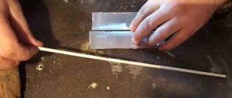
Next, the filler element is inserted into the holder, the arc is ignited and a weld pool is formed. The arc is ignited by tapping (striking) the tip of the working element on a metal surface.
During operation, the visible part of the filler element should not exceed 7 cm. Advancement along the joint should be uniform, taking into account the melting of the edges and the formation of the joint.
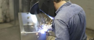
Welding parts, as well as gouging with a carbon electrode, can be done at home, but for this you need to use factory-made equipment. Homemade units are not suitable for such welding due to the lack of ability to adjust the current strength.
Purpose and types of planers
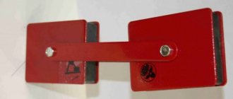
The planer is a hand-held cutter for air-arc processing of metal. The device consists of a clamp for the working electrode, an air supply mechanism with nozzles, a burner power supply system and a handle for the operator. To connect to a DC source, the package includes a 2-meter power cable with an installation kit.
This device is necessary for removing flaws in the workpiece, cleaning the resulting welds, straightening the bevel of cuts, as well as manually cutting and punching metal sheets. During operation, the electrode melts the metal, and the air flow removes it from the working area. Such operations are united by the term “gouging” (since during operation a small layer of surface material is removed), which was the reason for the name of the cutter – “planer”.
Description of technology
Air arc cutting is applicable at home. However, as with other treatments, safety is important when cutting.
Before starting welding and gouging work, the equipment is checked for serviceability. As well as metal preparation - cleaning and degreasing. After this, the welding mode is adjusted and the current parameters are set.
You should not set this parameter to high values. Excessive current will quickly evaporate the copper coating of the filler material. This will affect the quality and uniformity of melting of the body of the part.
In addition to welding equipment, a compressed air cylinder is prepared. It should not have any damage or dents.
After making sure that the cylinder is in good condition, the pressure is adjusted. For air arc gouging, four to six bar is sufficient.
The filler element is inserted into the holder so that the visible part does not exceed a length of 10 cm. Air is supplied and the arc is ignited.
After the formation of the weld pool, compressed air is directed to the working area. Both parts of the treatment should be carried out evenly.
Gouging
Gouging is a type of thermal cutting of metals. It is used when cutting the root of a weld for subsequent welding, for melting defective areas of welds and defects in castings, for removing welded temporary assembly fixtures, etc. There are several gouging methods, of which the most common in the hull shops of shipbuilding plants are gas and air-arc.
Gas gouging consists of the fact that the metal being processed, heated by the oxygen-acetylene flame of a special cutter, is partially melted and burned in a stream of cutting oxygen, the resulting oxides are blown onto the surface of the product in the direction of gouging. As a result, a groove in the shape of a half-cylinder is obtained on the surface of the metal. Gas planing is carried out by a planer, which differs from a conventional cutter in the design of the head and mouthpieces. Planers are equipped with a set of replaceable mouthpieces, installed in accordance with the depth and width of the groove being cut. Gas gouging modes are assigned depending on the thickness of the metal being processed and the position of the structure in space.
Gas gouging begins by heating the starting point of smelting to a light red heat. In this case, the axis of the end of the mouthpiece is tilted 60-70° to the surface of the sheet being processed so that the luminous core of the planer's flame almost touches the surface of the sheet. After heating the area from which melting begins to a light red heat, the end of the mouthpiece is moved 10-15 mm from the surface of the sheet and after starting cutting oxygen, reducing the angle of inclination of the mouthpiece by 20-30°, gouging is performed. During the gouging process, the distance from the hole of molten metal to the end of the luminous core of the preheating flame remains constant (10-20 mm).
They change the dimensions of the groove, not only by using a mouthpiece of a different number, but also by changing the gouging modes; increase the depth of the groove, increasing the oxygen pressure, reduce the depth of the groove, reducing the angle of inclination of the mouthpiece.
Recently, instead of gas gouging, air-arc gouging has become increasingly recognized. The air arc gouging process is based on the melting of metal by an electric arc burning between a carbon electrode and the workpiece. The molten metal is removed from the formed groove by a jet of compressed air directed parallel to the electrode.
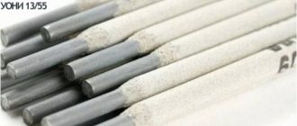
The installation for air-arc gouging (Fig. 7.7) consists of a welding generator and an electrode holder - a planer with a cable and hose attached to it, through which electric current and compressed air are supplied. The planer consists of a handle, an air tube with a valve and a head for attaching the electrode. An air hose is connected to the handle, inside which an electrical cable runs. Welding carbon electrodes with a diameter of 6, 8 and 10 mm with a copper-plated surface are used as electrodes. Copper coating promotes uniform combustion of the electrodes, reducing their consumption and making the gouging process more stable.
Rice. 7.7. Installation diagram for an air-arc gatehouse. 1 - workpiece; 2 - planer; 3 - welding generator.
Air-arc gouging modes are set depending on the size of the groove and the diameter of the electrode. To ensure a stable gouging process, it is necessary to maintain constant arc length and electrode angle. To increase the groove depth, the angle of inclination of the electrode is increased, and to decrease it, it is decreased while simultaneously increasing the gouging speed. In recent years, air-arc gouging with plate electrodes has been increasingly used. This makes it possible to increase the efficiency and quality of removal of temporary assembly fixtures, tacks, etc.
Grooves made by gas and air-arc guards must have smooth surfaces without significant changes in depth and width. Dimensional deviation is allowed within ±1.5 mm.
Types of metal cutting
Each method of processing materials using electrodes is characterized by its own advantages and disadvantages.
Depending on the type of cut, the following types of cutting are distinguished:
- The separation method involves the use of an electrode whose diameter is greater than the thickness of the main product. The rod should be positioned perpendicular to the working surface and moved along the line of the future cut;
- Surface cutting (gouging) is less popular and is used to make grooves on the surface and to remove defects. The electrode must be tilted 5-10° to the surface. Its movement is carried out with partial immersion of the rod into the cavity formed during the cutting process. To obtain a wide groove, the performer needs to make oscillatory movements with the electrode.
- Cutting holes is a simple process: a small hole is made in the metal, which is then gradually expanded to the required size. In this case, the electrode is located almost perpendicular to the surface, only small deviations are allowed.
Peculiarities
Air arc cutting uses carbon or graphite electrodes. The latter are more durable and have lower electrical resistance (0.0008 Ohm versus 0.0032 Ohm for a cube with an edge of 1 cm). It is possible to use copper-plated carbon electrodes.
DC converters or transformers are used as a power source for arc cutting of metal. The supply of compressed air to the cutter comes from a workshop network or a mobile compressor. The pressure should be in the range of 0.4–0.6 MPa. Its higher level is impractical, since too much flow reduces the stability of the electric arc.
In air-arc cutting, as a rule, direct current of reverse polarity is used as it is more productive. The use of a variable is advisable for minor work, for example, removing local irregularities in a weld. The use of direct current of direct polarity in such cases leads to an increase in the heating zone, which makes it difficult to remove the molten metal.
| The current value during air-arc cutting is calculated by the formula:I = Kxd,where d is the diameter of the electrode in mm, K is the linear coefficient, which is 46–48 A/mm for carbon and 60–62 A/mm for graphite electrodes. The resulting number gives the current value in amperes. |