Before we move on to the description of the high voltage source proposed for assembly, let us remind you of the need to observe general safety precautions when working with high voltages. Although this device produces an extremely low current output, it can be dangerous and will cause a rather unpleasant and painful shock if accidentally touched in the wrong place. From a safety point of view, this is one of the safest high-voltage sources, since the output current is comparable to that of conventional stun guns. The high voltage at the output terminals is about 10-20 kilovolts DC, and if you connect a spark gap, you can get a 15 mm arc.
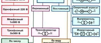
High voltage source circuit
The voltage can be adjusted by changing the number of stages in the multiplier, for example if you want it to light neon lights you can use one, if you want spark plugs to work you can use two or three, and if you want a higher voltage you can use 4. 5 or more. Fewer stages means less voltage but more current, which can make the device more dangerous. Paradoxically, the higher the voltage, the less difficult it will be to cause power-related damage as the current drops to negligible levels.
High voltage generator from a transistor liner
Hello, dear friends!
Today I suggest you assemble a high-voltage generator using just one transistor from a TVS-110PTs15 line transformer with an UN9/57-13 voltage multiplier from an old color TV. The circuit is quite simple, built on the principle of blocking a generator and contains a small number of parts. Circuit of a high voltage generator from a liner on one transistor
To assemble the generator, you will need one KT819G transistor, or an imported analog TIP41C, but it is best to use MJE13009, since this transistor can withstand current up to 12 A and, accordingly, will heat up less. Personally, I used MJE13009 in my generator. Be sure to coat the transistor with thermal paste and install it on a radiator, preferably with a fan.
You will also need two 5-watt resistors. At 100 ohms and 240 ohms, the resistors in my generator got very hot and I decided to glue a small radiator with “poxy-pol”. The most important part of the generator is the TVS-110PTs15 line transformer; it is possible to use TVS-90LTs5 and other similar ones from old color, black-and-white and even tube TVs.
Linear transformer TVS-110PTs15
A couple of additional windings need to be wound on the magnetic core of the transformer. Coil L1 contains 10 turns, wound with wire with a diameter of 1 millimeter. We wind coil L2 with 1.5 millimeter wire, 4 turns in total. Both coils should be wound in the same direction. The secondary high-voltage winding remains unchanged.
Line transformer TVS-110PTs15 with two additional windings
The voltage multiplier UN9/27-13 or similar also needs minor modification. It is necessary to remove two unused terminals on it, marked in the picture with red arrows, then isolate these places with “poxy-pol”. It’s not necessary to do this, but if you accidentally touch these conclusions during the experiment... Your hair will stand on end and it won’t seem like much, of course it won’t kill you with an electric shock, there are very few amperes there, but it can burn you. A 470 ohm resistor is installed between the line transformer and the multiplier.
How it works
After pressing the button, the IR diode turns on and the light beam hits the optocoupler sensor, this sensor has an output resistance of about 50 ohms, which is enough to turn on the 2n2222 transistor. This transistor supplies battery energy to power the 555 timer. The frequency and duty cycle of the pulses can be adjusted by changing the ratings of the trim components. In this case, the frequency can be adjusted using a potentiometer. These oscillations, through the BD679 transistor, which amplifies the current pulses, enter the primary coil. An alternating voltage increased by 1000 times is removed from the secondary and rectified by an explosive multiplier.
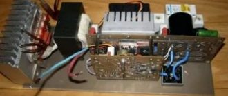
Parts for assembling the circuit
The microcircuit is any timer of the KR1006VI1 series. For the coil - a transformer with a winding resistance ratio of 8 Ohms: 1 kOhm. The first thing to consider when choosing a transformer is size, as the amount of power they can handle is proportional to their size. For example, the size of a large coin will give us more energy than a small transformer.
The first thing you need to do to rewind it is to remove the ferrite core to access the coil itself. In most transformers, the two parts are glued together, just hold the transformer with pliers over a lighter, just be careful not to melt the plastic. After a minute, the glue should melt and you need to break it into two parts of the core.
Keep in mind that ferrite is very brittle and cracks quite easily. To wind the secondary coil, 0.15 mm enameled copper wire was used. Winding until almost full, so that later there is enough for another layer of thicker wire 0.3 mm - this will be the primary. It should have several dozen turns, about 100.
Why is an optocoupler installed here? It will provide complete galvanic isolation from the circuit; there will be no electrical contact between the power supply button, the microcircuit and the high-voltage part. If a high power supply voltage accidentally breaks through, you will be safe.
It is very easy to make an optocoupler; insert any IR LED and IR sensor into a heat-shrinkable tube, as shown in the picture. As a last resort, if you don’t want to complicate matters, remove all these elements and supply power by closing the K-E transistor 2N2222.
Pay attention to the two switches in the circuit, this is done because each hand must be used to activate the generator - this will be safe and reduces the risk of accidental activation. Also, while operating the device, you should not touch anything other than the buttons.
When assembling the voltage multiplier, be sure to leave enough clearance between the elements. Trim any protruding leads as they can cause corona discharges which greatly reduce efficiency.
We recommend insulating all exposed contacts of the multiplier with hot melt adhesive or other similar insulating material and then wrapping them in heat shrink tubing or electrical tape. This will not only reduce the risk of accidental impacts, but will also improve the efficiency of the circuit by reducing losses through air. Also, for insurance, they added a piece of foam between the multiplier and the generator.
The current consumption should be approximately 0.5-1 ampere. If more, it means the circuit is poorly configured.
High voltage voltage source
Today, cases of counterfeit MOS transistors appearing on the electronics market have become more noticeable. Therefore, an urgent task is the input control of the main parameters of these semiconductor devices, for example, breakdown voltage. The breakdown mechanism of a field-effect transistor can be explained by the occurrence of an avalanche process in the gate-channel junction. The gate-channel diode reverse voltage varies along the gate length, reaching a maximum value at the drain end of the channel. This is where the breakdown of the field effect transistor occurs. If the drain and source terminals are swapped, the breakdown voltage will hardly change.
The method for determining the breakdown voltage itself is based on the use of a high-voltage voltage source with the breakdown current limited to a safe value [1]. The work considers the option of constructing a source that provides an output voltage of up to 500 V and limits the breakdown current at 250 μA (Fig. 1).
Rice. 1. Breakdown voltage measurement model
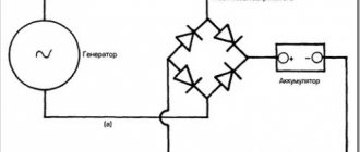
To create the basis of a high voltage voltage source, you can use a boost converter. The most rational and common option is a flyback voltage converter. This circuit solution is used in ignition circuits, charging flash capacitors or, for example, defibrators. The difference between the device under development and the standard converter is the presence of a limitation of the output current in the event of a breakdown. This limitation is implemented by a feedback circuit that monitors the voltage drop across resistor R4 (Fig. 2).
Rice. 2. Functional diagram of a high voltage voltage source
Resistor R3 limits the output current of the source to a level that is safe for humans and serves to ensure electrical safety when working with the device. Diode VD4 is protective and limits the output voltage of the source, and also serves as an additional safety measure. Resistor R2 discharges capacitor C1 after the device is turned off.
The performance of such a control algorithm was tested in the Micro-Cap program [2]. The converter operates in intermittent current mode (Fig. 3). The algorithm for calculating the storage choke is given in [3].
Rice. 3. Timing diagrams of the converter operation: a - voltage at the output V(Out) and voltage at the storage capacitor V(C1); b - current of the primary winding of the transformer I(W1); c - current through current sensor I(R4)
At the initial stage, the converter operates with a constant duty cycle D=0.8 (Fig. 4). In this case, power switch control pulses are generated by comparator DA1 at time intervals when the sawtooth voltage V(G1) supplied to the non-inverting input of the comparator is greater than the threshold voltage (voltage at the inverting input V(R1)). At this stage, this voltage is set by the reference voltage V1. Further, when the protective diode VD4 breaks down, the voltage on the current sensor R4 begins to increase, which in turn causes an increase in the voltage at the inverting input V(R1), and when the voltage of the reference source V1 exceeds the width of the control pulses decreases until the voltage V(R1) will not be established at the level at which the current through the sensor is stabilized and equal to 250 μA.
Rice. 4. Timing diagrams of the control system operation: a - voltage from the generator V(G1) and voltage at the inverting input of the comparator V(R1); b - signal from the output of the comparator Vout (DA1)
The PWM operating algorithm in this circuit is typical for such devices, so to create this high-voltage source, you can use standard solutions for key element control circuits. In particular, the control circuit can be implemented on any PWM controller with a duty cycle greater than 0.5.
Literature:
- AN-975B. Measuring the characteristics of a MOSFET // International Rectifier/
- Amelina M. A., Amelin S. A. Micro-Cap circuit modeling program. Versions 9, 10. [Electronic resource]: textbook. allowance / Amelina M.A., Amelin S.A - Electron. text data - St. Petersburg: Lan, 2014. - 632 p. Access mode: URL https://e.lanbook.com/books/element.php?pl1_id=53665
- Brown M. Power sources. Calculation and design: Per. from English - K.: “MK-Press”, 2007. 288 p.
HV generator testing
Two different transformers were tested, both with excellent results. The first had a smaller ferrite core and therefore less inductance, operated at a frequency of 2 kHz, and the other about 1 kHz.
When starting for the first time, first check the NE555 generator to see if it is working. Connect a small speaker to leg 3 - you should hear sound coming from it as the frequency changes. If everything gets very hot, you can increase the resistance of the primary winding by winding it with a thinner wire. And a small heatsink for the transistor is recommended. And the correct tuning frequency is important to avoid this problem.