Structural elements
Designation of welded contact connection in the drawings.
State standardization describes in detail similar elements, indicating acceptable sizes and designations:
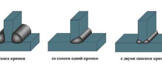
- edges are the edges of the part that are joined during welding;
- gaps - the distance between the edges, indicated by the letter b;
- bluntness - unbeveled end of the edge, c;
- the bevel angle is the acute angle between the edge and the end, β;
- a similar parameter between beveled edges is the cutting angle , a;
- the width of the seam joint in the drawing is indicated by the letter e;
- seam leg - letter k;
- thickness - indicated by t at the butt and α fillet welds.
All structural elements of welding joints in reference books are referred to as geometric parameters; a complete list of sizes and their designations is given in GOST 15878-79 KT-5.
The principle of choosing the type of seam and welding method
The basis of any development is a set of certain calculations defined in the technical specifications for the development. That is, when choosing the type of joint and the method of obtaining it, the designer must carry out all the necessary strength and force calculations, which should determine the thickness of the metal being welded and the geometric parameters of the joint.
As a result of the calculations, the welding method will be determined, for example, gas-shielded arc welding or traditional manual welding using electrodes. Depending on this, the designer must refer to GOST, which contains all the necessary information.
Types of welded joints
Every designer knows that domestic GOSTs define five types of seams:
butt – C;
overlap - N;
T-bars - T;
corner – U;
end
Each of these joints can be used depending on the requirements for the design of the resulting unit. Read more about the types and types of welds and connections
In addition to the letter designations indicated in brackets, there are additional (auxiliary) signs that are designed to ensure completeness of information about the weld.
Additional (auxiliary) signs
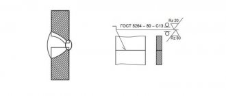
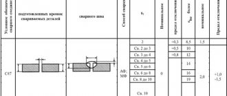
GOST 5264-80 and GOST 14771-76 show the main types of welded joints, their designation and permissible dimensions. For example, a T-weld made from sheet steel with a thickness of 8 - 100 mm has a weld designation in the drawing - T8.
| Shape of prepared edges | Cross-sectional shape | Thickness of welded parts, mm | Symbol of welded joint | |
| Prepared edges | Completed seam | |||
| With a curved bevel of one edge | 15 — 100 | T2 | ||
| With two symmetrical bevels on one edge | ||||
| 12 — 100 | ||||
The same documents indicate mandatory dimensions, for example, the leg of a seam. Its parameters are selected based on the size of the yield strength. So, if the yield strength has not reached 400 MPa, then with a thickness of the welded parts from 22 to 32 mm, the weld leg should be 8 mm. When using standard weld sizes, there is no need to indicate its dimensions on the drawings.
If the designer has decided to use a non-standard seam, then its dimensions must be indicated in full
Overlap
This type of connection is often used for resistance spot welding ; if another technology is used, we will get a large consumption of material and working time, and the seam will have to be welded on each side. The edges are not cut, but they are carefully trimmed to prevent the appearance of burrs during mechanical separation or sagging when using a gas cutter. The ends and adjacent surface at a distance of 20 mm from the edge are cleaned to a shine and degreased.
Structural elements of welded joints made by resistance seam welding
Crap. 2 Damn. 3| no less | Single row seam no less | no less |
| Aluminum, magnesium and copper alloys | ||
| 6 | ||
| 9 |
Note. Reducing the size is allowed and the size must correspond to those indicated in the table.
table 2
| Welding method | no less | Single row seam no less | no less |
| Aluminum, magnesium and copper alloys |
Note. Reducing the size is allowed, but the size must correspond to those indicated in the table.
Table 3
| Connection group | no less | Single row seam no less |
| St. 0.8 to 1.0 |
| mm | |
| no less | Single row seam no less |
| mm | ||
| Single row seam no less | ||
| Welding method | Connection group | no less |
| 10,0 |
| mm | ||
| Single row seam no less | ||
| Welding method | Connection group | no less |
4. The amount of overlap for multi-row seams with a chain arrangement of points
; with a staggered arrangement of points.
5. Depending on the type of overlap of the welded joint, the amount of overlap should be determined in accordance with the drawing. 4.
Types of welding
GOST 15878 of 1979 was issued to replace a similar document dated 1970 - it described the main types of contact welding techniques, as well as other methods, some of which we will consider in more detail.
Spot
This welding method of small-sized contact is used in many areas of human activity: from construction to the production of aircraft and rockets. For example, when creating the durable skin of modern airliners made of aluminum and its alloys, millions of spot welded objects are located on the hull, which form a strong connection.
The principle of operation of spot welding machines is extremely simple - the metal at the joint is instantly heated to the melting temperature with simultaneous strong compression on both sides, resulting in a durable and aesthetic seam that can withstand any loads and vibrations. This method allows you to reduce to a minimum the time of joining metals into one whole . This technique is used to firmly connect sheet material and metal rods by butt welding.
Embossed
Resistance welding GOST 15878-79 is a type of spot technique when it is necessary to connect structures with complex edge relief.
In practice, many varieties of this type of welding are used, and the most common is the overlap of sheets, which is carried out using reliefs of different configurations. For example, spherical surfaces with complex convexities that, when combined, form a circular shape. During the application of the relief technique, plastic deformation of the welded material occurs , which is typical for conditions conducive to the formation of a reliable connection after final hardening.
Suture
Used to create straight and continuous seams - the machine creates a series of points, onto which similar points are subsequently superimposed . As a result of such an intense attack, a strong connection is created that fully complies with GOST requirements. Three types of techniques are used:
- Continuous option. An even seam is created by the constant mechanical action of the rollers on the surfaces being joined and the continuous supply of electrical potential. Such devices work very efficiently, but are prone to overheating, and the rollers quickly fail due to high loads - the contact surfaces are erased. Pre-processing of the parts to be joined is required.
- With the step method, the roller mechanism is in constant contact with the welding surface and puts pressure on the part, which moves intermittently, which avoids the negative effects of overheating and subsequent deformation.
- The broken line is characterized by the use of pulsating pulses. The workpiece is in constant motion between two pressure rollers, and the points constantly overlap each other to form a sealed seam.
The third option is used more often and is more popular than the previous two.
Condenser
GOST for capacitor welding can be easily found in the list of relevant documents, and a similar technology was developed at the beginning of the last century and has not undergone significant changes during its use, having proven itself to be a reliable and simple method of joining metals. The welding unit has a simple design, there is a small load on the electrical network, and the productivity is quite high.
The essence of the process is similar to resistance welding, only here the current is supplied pulsed and powerful , for which powerful capacitors with a large capacity are used.
Schematic representation of capacitor welding.
How the technology works
The method is based on the strong bonding of parts with 2 conductors to which an electrical impulse is applied. This process creates an arc that melts the metal. After the impulse, compression of objects under load is observed.
The welding process proceeds as follows:
- capacitors accumulate the required amount of energy supplied through the primary circuit;
- the electrode contacts the metal, transmitting to it a stream of particles that promote heating and melting;
- the pulse is sent again, the next connection point is formed.
Capacitor welding technology.
The method is effective when working with elements with a thickness of no more than 1.5 mm.
Block design
The contact unit is responsible for fixing and moving the rods. The design of a simple block involves attaching a manual sample. More complex options fix the lower one and leave the upper rod movable. The finished structure resembles a vice. A short thin copper rod is fixed here. It should move freely in a vertical plane. Therefore, a screw regulator is installed in the upper part, changing the pressure.
The moving platform and the base of the power unit are isolated from each other. For ease of operation, the device is equipped with a flashlight.
Features of the point method
When using this method, the welding process includes the following steps:
- Preparation of parts. Surfaces are cleaned of dust, rust, and oils.
- Comparison of elements. The parts are installed between the contacts and fixed with them.
- Start the device using the key. The first weld point is formed. Finish the work by removing the electrodes.
- Installation of the rod, supply of an electrical impulse, connection of parts at the next point. Work continues until the desired result is obtained.
Spot welding is a high-tech method of welding parts.
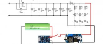
Homemade devices and circuits
DIY devices are often used in home workshops. A minimum area of space is sufficient to carry out the work.
We recommend reading: The principle of acetylene welding with oxygen
To assemble devices, 2 types of circuits are used:
- Simple. The device is capable of connecting elements with a thickness of no more than 0.5 mm. In other cases, he fails to cope with the task. The device can be assembled in a home workshop. The principle of operation is based on the issuance of a pulse by a transformer. One end of the winding is connected to the electrode, the other to the workpiece being processed.
- Complex. An electrical circuit includes a large number of functional elements. Assembly will require a lot of time and materials. The finished machine allows you to weld parts with a thickness of 1-1.5 mm.
Designation on drawings
The welder must read the drawing, as they say from the sheet - the correct execution of welding work depends on this. All types of welding are indicated on the drawings in accordance with the requirements of GOST, where the types of symbols are specified, for example:
- the solid line is a visible seam;
- the dotted line is the invisible part of the seam;
- contours with a number are multi-layer structures.
External arrows indicate the exact location of welding work, and the type of welding is indicated by letter symbols, for example, contact welding GOST 15878-79 in the drawings is designated as Kt or KT. In addition, the designations indicated in the table are used:
| Welded corner | Litera | additional information |
| Butt | WITH | seam type plus welding type |
| Angular | U | seam + corner leg + seam point + welding type |
| Tavrovy | E | seam + angle leg + welding type |
| Overlapping | N | weld point diameter, roller pit welding width |
I. R. Nikolaevsky, education: college, specialty: master welder, work experience since 2001: “Young performers are required to understand the designations given in GOST in order to correctly perform the assigned types of welding and avoid mistakes that negatively affect the quality and reliability of the welded joint.”
Instructions for carrying out capacitor welding
Before starting work, it is necessary to study the main stages of work and become familiar with safety precautions.
Precautionary measures
When working with capacitor welding equipment, observe the following rules:
- Do not use ungrounded devices.
- Before starting work, check the condition of the device body. If it is damaged, there is an increased risk of electrical injury.
- The device can only be operated with dry hands. It is worth checking the area surrounding the artist for the presence of moisture.
- Check the presence of an emergency shutdown button at the welding station.
- Before starting work, stand on a dielectric mat and put on a special suit. Cooking in clothes made of synthetic fabrics is prohibited.
- When changing the rod or installing parts, use glasses and gloves that protect from heat.
- The work area is fenced off with a screen. This prevents fires from bouncing sparks and splashes.
- The welding machine should not be installed near flammable liquids and materials.
- When working in enclosed spaces, ensure constant ventilation.
- If any problems occur, welding is suspended and the equipment is disconnected from the network.
Recommended reading: What is TIG welding
Capacitor welding is a quick way to qualitatively join two metal parts.
Using a general example
The algorithm of actions for capacitor welding includes the following steps:
- Preparation of parts to be joined. Remove traces of corrosion and dust, degrease surfaces.
- Comparison of blanks. The elements are firmly fixed in the chosen position.
- Placing parts between rods.
- Making contacts.
- Starting the welding installation, supplying a short-term pulse of the required power.
- Return the electrodes to their original position.
- Removing parts, assessing the quality of the welded joint.
If necessary, during the welding process the position of the elements is changed and work continues in the same way.
Working with studs
The welded element is installed between the rods. Bring the pin to the main part and set up the device. After applying the pulse, the leg of the fastening element melts along with the surface of the base. After the metal cools, a durable seam is obtained.
Welding studs is considered one of the most labor-intensive and complex processes in welding.
Welding nuts
To attach the fastener to the sheet metal, a powerful pulse lasting up to 5 milliseconds is applied. The bottom of the nut melts along with the base. The fasteners are pressed into the melt with a welding gun. A strong connection is obtained. The method is suitable for welding fasteners to sheets with a thickness of more than 5 mm.