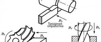
Cutting speed
The most important mode during milling can be called cutting speed. It determines over what period of time a certain layer of material will be removed from the surface. Most machines have a constant cutting speed. When choosing a suitable indicator, the type of workpiece material is taken into account:
- When working with stainless steel, the cutting speed is 45-95 m/min. Due to the addition of various chemical elements to the composition, hardness and other indicators change, and the degree of workability decreases.
- Bronze is considered a softer composition, so this mode when milling can be selected in the range from 90-150 m/min. It is used in the manufacture of a wide variety of products.
- Brass has become quite widespread. It is used in the manufacture of locking elements and various valves. The softness of the alloy allows you to increase the cutting speed to 130-320 m/min. Brasses tend to increase in ductility when exposed to high heat.
- Aluminum alloys are very common today. In this case, there are several design options that have different performance characteristics. That is why the milling mode varies from 200 to 420 m/min. It is worth considering that aluminum is an alloy with a low melting point. That is why, at high processing speeds, there is a possibility of a significant increase in the plasticity index.
There are quite a large number of tables that are used to determine the main operating modes. The formula for determining cutting speed revolutions is as follows: n=1000 V/D, which takes into account the recommended cutting speed and the diameter of the cutter used. A similar formula allows you to determine the number of revolutions for all types of processed materials.
The milling mode in question is measured in meters per minute cutting parts. It is worth considering that experts do not recommend driving the spindle at maximum speed, as wear increases significantly and there is a possibility of damage to the tool. Therefore, the result obtained is reduced by approximately 10-15%. Taking this parameter into account, the most suitable tool is selected.
The rotation speed of the tool determines the following:
- The quality of the resulting surface. For the final technological operation, the largest parameter is selected. Due to axial rotation with a large number of revolutions, the chips are too small. For roughing operations, on the contrary, low values are selected, the cutter rotates at a lower speed, and the chip size increases. Due to fast rotation, a low surface roughness is achieved. Modern installations and equipment make it possible to obtain a mirror-type surface.
- Labor productivity. When setting up production, attention is also paid to the productivity of the equipment used. An example is the workshop of a machine-building plant, where mass production is being established. A significant decrease in processing modes causes a decrease in productivity. The most optimal indicator significantly increases labor efficiency.
- The degree of wear of the installed tool. Do not forget that when the cutting edge rubs against the surface being processed, severe wear occurs. With severe wear, the accuracy of the product changes and labor efficiency decreases. As a rule, wear is associated with strong surface heating. That is why high-throughput production lines use equipment that can supply coolant to the material removal zone.
In this case, this parameter is selected taking into account other indicators, for example, feed depth. Therefore, the technological map is drawn up with the simultaneous selection of all parameters.
§ 4. Elements of cutting modes during milling
Cutting speed v
— path length (in meters) covered in one minute by the point of the main cutting edge most distant from the axis of rotation.
For one revolution of the cutter, the point of the cutting edge located on the cutter circle with diameter D will travel a path equal to the length of the circle, i.e. πD.
To determine the length of the path traveled by this point per minute, you need to multiply the path length per revolution by the number of revolutions of the cutter per minute, i.e. nDn mm/min. If the cutting speed is expressed in meters per minute, then the formula for cutting speed in milling will be
If it is necessary to determine the number of revolutions of the cutter per minute, then the formula will take the form
When milling, the following types of feeds are distinguished (Fig. 12): feed per tooth, feed per revolution and minute feed. According to the direction, longitudinal, transverse and vertical feeds are distinguished.
Rice. 12. Types of serves
Feed per tooth
(Sz, mm/tooth) is the amount of movement of the table with the workpiece being processed or the cutter during its rotation by one tooth.
Feed per cutter revolution
(So, mm/rev) is the amount of movement of the table with the workpiece being processed or the cutter per revolution of the cutter.
The feed per revolution is equal to the feed per tooth multiplied by the number of cutter teeth:
So = Sz • Z.
Minute feed (Sm, mm/min) is the amount of relative movement of the table with the workpiece being processed or a cutter in one minute.
The minute feed is equal to the product of the feed per revolution of the cutter and the number of revolutions of the cutter per minute:
Sм = So • n = Sz • z • n mm/min.
As can be seen in Fig. 12, each tooth of the cutter removes the same chips in the form of a comma. The chip removed by one tooth is determined by two arcs of contact between adjacent teeth. The distance between these arcs, measured along the radius of the cutter, is variable. It determines the thickness of the cut. From Fig. 12 it can be seen that the slice thickness varies from zero to the maximum value.
On the workpiece being processed, during milling, a distinction is made between the machined surface, the machined surface and the cutting surface (Fig. 13).
Rice. 13. Surfaces during milling
For all types of milling, cutting depth and milling width are distinguished. Milling depth is the distance between the machined and machined surfaces (see Fig. 13). Milling width is the width of the surface processed in one pass. Typically, the milling depth is usually denoted by the letter t, and the milling width by B. This is true in the case when these parameters are considered technological. The parameter (depth or width of milling) that affects the length of contact of the main cutting edges of the cutter with the workpiece will be denoted by the letter B, the second, which does not affect the specified length, will be denoted by the letter t. In Fig. Figure 14 shows that the parameter influencing the length of contact of the main cutting edges with the workpiece being processed and designated by the letter B, will be the milling width when milling a plane with a cylindrical cutter (Fig. 14, a), a groove or shoulder with a disk cutter (Fig. 14, b and c ), or the depth of milling when milling a groove or shoulder with an end mill (Fig. 14, d and e), a shoulder with an end mill (Fig. 14, f), an end mill with an angled blade (Fig. 14, g), symmetrical milling with an end mill ( Fig. 14, h) and asymmetrical milling with an end mill (Fig. 14, i).
Rice. 14. Cutting depth and milling width
Therefore, in the future, the letter B will denote the width of milling when processing with cylindrical, disk, cutting and shaped cutters or the depth of milling when processing with face and end mills. The letter t is the depth of milling when processing with cylindrical, disk, cutting and shaped cutters or the width of milling when processing with face and end mills.
The layer of material that must be removed during milling is called machining allowance. Depending on its size, the allowance can be removed in one or more passes. There are rough and finishing milling. During rough milling, processing is carried out with the maximum cutting depths and feeds per tooth allowed under the processing conditions. Finish milling produces parts with final dimensions and a surface of a high roughness class.
Depth of cut
The other most important parameter is the milling depth. It is characterized by the following features:
- The cutting depth is selected depending on the material of the workpiece.
- When choosing, attention is paid to whether roughing or finishing is carried out. When roughing, a larger plunge depth is selected, since a lower speed is set. During finishing, a small layer of metal is removed by setting the tool to a high rotation speed.
- The indicator is also limited by the design features of the tool. This is due to the fact that the cutting part can have different sizes.
The depth of cut largely determines the performance of the equipment. In addition, such an indicator in some cases is selected depending on what kind of surface needs to be obtained.
The power of the cutting force during milling depends on the type of cutter used and the type of equipment. In addition, rough milling of a flat surface is carried out in several passes when it is necessary to remove a large layer of material.
A special technological process can be called the work of obtaining grooves. This is due to the fact that their depth can be quite large, and the formation of such technological recesses is carried out exclusively after finishing the surface. Milling T-slots is carried out using a special tool.
Immersion and cutting edge
Milling should be performed using a drilling method similar to drilling. If the end does not touch the material being processed, it is necessary to reconfigure. Due to differences between the edges of the passage, the quality of processing of the sides differs. Recommended:
- mill internal contours clockwise;
- mill external contours counterclockwise.
Thanks to milling using this system, the lower quality side will be cut off.
Important! The deeper the dive, the higher the likelihood of failure. At high speed, the cutter should plunge to a minimum depth, and cutting should be performed in several passes.
Innings
The concept of feed is similar to plunge depth. Feed during milling, as with any other operation for machining metal workpieces, is considered the most important parameter. The durability of the tool used largely depends on the feed. The features of this characteristic include the following points:
- How thick is the material removed in one pass?
- Productivity of the equipment used.
- Possibility of roughing or finishing processing.
A fairly common concept can be called feed per tooth. This indicator is indicated by the tool manufacturer and depends on the cutting depth and design features of the product.
As previously noted, many indicators are related to the cutting mode. An example is cutting speed and feed:
- As the feed value increases, the cutting speed decreases. This is due to the fact that when removing a large amount of metal in one pass, the axial load increases significantly. If you choose high speed and feed, the tool will quickly wear out or simply break.
- By reducing the feed rate, the permissible processing speed also increases. By quickly rotating the cutter, it is possible to significantly improve the quality of the surface. At the time of finishing milling, the minimum feed value and maximum speed are selected; when using certain equipment, an almost mirror-like surface can be obtained.
A fairly common feed value is 0.1-0.25. It is quite sufficient for processing the most common materials in various industries.
Milling width
Another parameter that is taken into account when machining workpieces is the milling width. It can vary over a fairly large range. The width is selected when milling on a Have machine or other equipment. Among the features we note the following points:
- The milling width depends on the diameter of the cutter. Such parameters, which depend on the geometric features of the cutting part and cannot be adjusted, are taken into account when directly selecting a tool.
- The milling width also influences the selection of other parameters. This is because as the value increases, the amount of material removed in one pass also increases.
In some cases, the milling width allows you to obtain the required surface in one pass. An example is the case of obtaining shallow grooves. If cutting a flat surface of large width is carried out, the number of passes may differ slightly; it is calculated depending on the width of the milling.
Properties of stainless steels that complicate milling
Characteristics that make it difficult to process workpieces by cutting include:
Self-strengthening during deformation, called “hardening”. When the cutting edge of the cutter is pressed, the metal is deformed, as a result of which its hardness increases. If another pass is required, the tool will need to cut away the highly hardened layer. One of the reasons that causes this problem is an incorrectly selected and worn tool. Reduced thermal conductivity, making it difficult to remove heat from the cutting zone. The workpiece and chips absorb a small part of the heat, and the rest is transferred to the tool, which reduces its service life due to intense wear. High hardness and strength provided by alloying elements - nickel, titanium and others. When processing such material, the cutter experiences much greater loads compared to the process of cutting conventional carbon steels. Therefore, the tool quickly fails. Metal adhesion to the edge of the cutter. This leads to a violation of its geometry and an increase in cutting force. Difficult chip crushing and the formation of burrs on the workpiece. These problems are especially relevant in cases of incorrect selection of tools.
How to choose a mode in practice?
As previously noted, in most cases, technological maps are developed by a specialist and the master can only select the appropriate tool and set the specified parameters. In addition, the master must take into account the condition of the equipment, since limit values can lead to breakdowns. In the absence of a technological map, you have to select milling modes yourself. Calculation of cutting conditions during milling is carried out taking into account the following points:
- Type of equipment used. An example is the case of cutting when milling on CNC machines, when higher processing parameters can be selected due to the high technological capabilities of the device. On older machines that were put into operation several decades ago, lower parameters are selected. At the time of determining suitable parameters, attention is also paid to the technical condition of the equipment.
- The next selection criterion is the type of tool used. Various materials can be used in the manufacture of cutters. For example, a version made of high-quality high-speed steel is suitable for processing metal at high cutting speeds; a milling cutter with refractory tips is preferably selected when it is necessary to mill a hard alloy with a high feed rate during milling. The sharpening angle of the cutting edge, as well as the diametrical size, also matters. For example, as the diameter of the cutting tool increases, the feed rate and cutting speed decrease.
- The type of material being processed can be called one of the most important criteria by which the cutting mode is selected. All alloys are characterized by a certain hardness and degree of machinability. For example, when working with soft non-ferrous alloys, higher speed and feed rates can be selected; in the case of hardened steel or titanium, all parameters are reduced. An important point is that the cutter is selected not only taking into account cutting conditions, but also the type of material from which the workpiece is made.
- The cutting mode is selected depending on the task at hand. An example is rough cutting and finishing cutting. Black is characterized by a large feed and a low processing speed; for finishing, the opposite is true. To obtain grooves and other technological holes, the indicators are selected individually.
As practice shows, the depth of cut in most cases is divided into several passes during roughing, while during finishing there is only one. For various products, a table of modes can be used, which significantly simplifies the task. There are also special calculators that calculate the required values automatically based on the entered data.
Basic concepts about the operation of milling machines
Equipment can be completely different; the main classification depends on the plane in which the working area is located. In this regard, a distinction is made between vertical and more common horizontal frames. Accordingly, the location of the spindle and fasteners will be different. According to their specifications, there are universal (multifunctional) machines, as well as specialized ones, for example:
to form smooth planes;
for cutting figured grooves;
gear cutting equipment (creating gear connections) and so on.
These were listed examples when working on metal. And for wood - manual, stationary, spindle and drum (they are very dangerous, so they are rarely used now, but they are very effective).
Separately, it is worth mentioning those machines that are equipped with a numerical control panel (CNC). They have the following advantages:
Ease of operation: the operator does not need to make many movements, you can only observe and control the actions.
The program independently calculates the optimal motion pattern and cutting mode during milling. This will be the shortest route for moving the cutter with maximum efficiency.
Increased cutting accuracy. Here are the minimum permissible errors, which cannot be compared with those that occur during mechanical, manual processing.
Returning to simpler machines, let's see what main components it has:
Bed. It is strong and should withstand almost any load. It includes a built-in gearbox. This block is designed to regulate the rotation of a vertically standing spindle, as well as the cutter that is mounted on it.
Table with cross runners. Workpieces that are subject to longitudinal movement are attached to it. Also at the bottom there is an object responsible for feeding. It includes different handles to determine movements.
Versatility increases if a rotary table is present - there are more functions that can be performed on milling equipment. In addition, the highly versatile devices additionally have two spindles, which makes it possible to implement various milling technologies.
Selecting a mode depending on the type of cutter
To obtain the same product, a variety of types of cutters can be used. The choice of basic milling modes is carried out depending on the design and other features of the product. Cutting modes when milling with disk cutters or other design options are selected depending on the following points:
- The rigidity of the system used. An example is the features of the machine and various equipment. The new equipment is characterized by increased rigidity, which makes it possible to use higher processing parameters. On older machines, the rigidity of the system used is reduced.
- Attention is also paid to the cooling process. Quite a large amount of equipment provides for the supply of coolant to the processing zone. Due to this substance, the temperature of the cutting edge is significantly reduced. Coolant must be supplied to the material removal zone continuously. At the same time, the resulting chips are also removed, which significantly improves cutting quality.
- Processing strategy also matters. An example is that the production of the same surface can be carried out by alternating various technological operations.
- The height of the layer that can be removed in one pass of the tool. The limitation may depend on the size of the tool and many other geometric features.
- Size of processed workpieces. Large workpieces require a tool with wear-resistant properties that will not heat up under certain cutting conditions.
Taking into account all these parameters allows you to select the most suitable milling parameters. This takes into account the distribution of allowance when milling with spherical cutters, as well as the features of processing with an end mill.
The classification of the instrument in question is carried out according to a fairly large number of characteristics. The main thing is the type of material used in the manufacture of the cutting edge. For example, the VK8 cutter is designed to work with workpieces made of hard alloys and hardened steel. It is recommended to use this design option at low cutting speeds and sufficient feed. At the same time, high-speed cutters can be used for processing with a high cutting rate.
As a rule, the choice is made taking into account common tables. The main properties are:
- Cutting speed.
- Type of material being processed.
- Type of cutter.
- Speed.
- Innings.
- Type of work performed.
- Recommended feed per tooth depending on the cutter diameter.
The use of regulatory documentation allows you to select the most suitable modes. As previously noted, only a specialist should develop the technological process. Mistakes made can lead to tool breakage, a decrease in the quality of the workpiece surface and errors in the tools, and in some cases, equipment breakdown. That is why you need to pay a lot of attention to choosing the most suitable cutting mode.
Type of cutter: 1 or 2 blades?
In advertising production
Most often, 1 and 2-flute cutters are used, less often 3-flute cutters.
Four-blade or multi-blade cutters cannot cut thick chips in soft materials and are generally not used. Their main problem when milling soft
materials is “baking” in the cavities of the cutter. Single-flute cutters provide better chip evacuation due to a more spacious cutter flute. Special cutters for aluminum have a large groove. Particularly advantageous when machining soft aluminum, in addition to polished cutters, are coatings with Titan-Nitrid (TiN).
The choice of the “ideal” type of cutter always depends on the material being processed:
When milling “soft” materials:
soft plastics (PVC, plexiglass, polystyrene foam), wooden materials (wood, fiberboard, plywood, chipboard), soft grades of aluminum and sandwiches (aluminum / plastics) benefit from sharp 1-flute cutters.
Since here the problem of faster dulling is preferable to the risk of clogging and breakage of the cutter. For hard plastics,
sharp 2-way ones with a fishtail profile are suitable.
When machining harder metals
such as brass, we can recommend 2-flute cutters with a flat grind.
When milling extremely rigid structural steel
or very high-quality steel, three or four entry cutters are used.
Cross-cut single cutter Single blade leaves large open space for chip evacuation
Three-flute cutter in cross section Three blades significantly reduce the space for chip evacuation
Differences between a cutter and an engraver
Many people use the terms “Cutter” and “Engraver” interchangeably. However, we are talking about two different tools. An engraver is a simple tool, splitting a cylinder in half, followed by a back grind. The shape may vary; the most common are triangular. Unlike milling cutters, they do not have a spiral chute to drain chips.
Milling cutter material: HSS or carbide?
In advertising technology, carbide cutters are predominantly used. Carbide (HM) is an expensive, man-made product that is agglomerated from fine powders (e.g. Wolfram-Carbid). During the agglomeration process, the shape of the cutter is immediately created and subsequently does not change (it is only sharpened). Carbide is extremely hard and wear-resistant, however, it is susceptible to vibration and shock. It is important when using HM cutters to have a stable, possibly heavier and more massive machine, a spindle with precise rotation and high-quality clamping collets. The material to be milled must be rigidly and motionlessly fixed on the machine. High speed steel (HSS) is used primarily where carbide is too sensitive: when milling stainless steel sheets, on shaky machines, or in cases where the clamping rigidity is not sufficiently ensured. HSS wears out much faster, but there is less risk of premature failure due to its viscosity. The life of a coated HSS cutter is significantly increased. For example, titanium nitride (TiN) increases service life by six times. Titan-Nitrid is significantly stiffer than HSS and also stiffer than HM. With Titan-Nitrid coating, HM tools also last longer, although the difference in hardness is negligible. The coverage has a more significant effect on the number of revolutions and feed. It can be increased and thus the processing time can be shortened. When milling aluminum, TiN prevents the dreaded baking of aluminum in the cutter. The coating acts like Teflon in a frying pan (the chips slide)
Speed and optimal feed
It is fundamentally considered: The higher the cutting speed (vc = p * d * n), the smoother the surface will be. However, the dullness of the cutter also increases with increasing cutting speed.
Calculation procedure:
1. Number of revolutions n:
Select the opening speed
vc
from the table. (If the cutting speed of the material varies greatly, check with reference books). Based on the data, calculate the spindle speed
n [U/min] = (vc [m/min] *1000) / (3.14 * d [mm])
2. Feed f:
Select the recommended feed per tooth (fz factor) using the same table and calculate the feed from there:
f [mm/min] = n * fz * z fz = feed per tooth z = number of blades
Example:
You want to rout hard aluminum with a 2-flute router bit, 3mm in diameter. From the table you find: vc = 100. 200 m/min. From this you calculate:
Max. speed: n = (200 * 1000) / (3.14 * 3) = 200,000 / 9.42 = 21.230 U/min
Corresponding feed: f = 21230 * 0.04 * 2 =
1698 mm/min
High feed rates - especially in metals - require a stable and quiet machine. In addition, the groove depth should not be too large (about 1 * d 1). For less stable machines or with increased milling depth, the mode is calculated as follows:
Max. speed: n = (200 * 1000) / (3.14 * 3) = 200,000 / 9.42 = 21.230 U/min
(same as above) Minimum.
speed: n = (100 * 1000) / (3.14 * 3) = 100,000 / 9.42 = 10.615 U/min
Corresponding feed (minimum): f = 10615 * 0.04 * 2 =
849 mm/min
You combine n=21230 U / min and f = 849 mm/min.
Selecting a mode depending on the material
All materials are characterized by certain performance characteristics, which must also be taken into account. An example is bronze milling, which is carried out at cutting speeds from 90 to 150 m/min. Depending on this value, the feed amount is selected. PSh15 steel and stainless steel products are processed using other parameters.
When considering the type of material being processed, attention is also paid to the following points:
- Hardness. The most important characteristic of materials is hardness. It can vary over a wide range. Too much hardness makes the part strong and wear-resistant, but at the same time the processing process becomes more complicated.
- Degrees of machinability. All materials are characterized by a certain degree of workability, which also depends on ductility and other indicators.
- Application of technology to improve properties.
A fairly common example is hardening. This technology involves heating the material followed by cooling, after which the hardness index increases significantly. Forging, tempering and other procedures for changing the chemical composition of the surface layer are also often carried out.
In conclusion, we note that today you can find simply a huge number of different technological maps, which you just need to download and use to obtain the required parts. When considering them, attention is paid to the type of workpiece material, type of tool, and recommended equipment. It is quite difficult to independently develop cutting modes; in this case, you need to do a preliminary check of the selected parameters. Otherwise, both the tool and the equipment used may be damaged.