Machine tools
Here are excerpts from GOST 28939-81 “Gauges for cylindrical threads. Types" Appendix 2 "Rules for the use of calibers"
Start of quote
1. External thread gauges
1.1.Threaded straight-through non-adjustable ring gauge PR (1)
The gauge controls the largest average diameter (reduced average diameter) and, at the same time, the largest internal diameter of the external thread. The outer diameter of the thread is not controlled by this gauge.
The gauge must screw freely onto the controlled thread. The screwability of a gauge with a thread means that the given average diameter of the thread is not larger than the established largest limit size, and the internal diameter of the external thread is not greater than the smallest internal diameter of the internal thread.
Control of the ring gauge should be carried out by control plug gauges KPR-PR (2) and KPR-NE (3). The wear of the ring gauge must be regularly monitored by the KI plug gauge (6).
1.2.Threaded control pass-through gauge-plug KPR-PR (2) for the new non-adjustable pass-through thread gauge-ring gauge PR (1).
The gauge controls the smallest average diameter (reduced average diameter) and, at the same time, the smallest outer diameter of the ring gauge.
The gauge must screw freely into the controlled ring gauge. The screwability of the control plug gauge with the ring gauge means that the given average diameter of the ring gauge is not less than the established smallest limit size, and the outer diameter of the ring gauge is not less than the largest outer diameter of the external thread.
1.3.Threaded control no-go gauge-plug KPR-NE (3) for the new non-adjustable go-through threaded gauge-ring gauge PR (1).
The gauge controls the largest average diameter of the new ring gauge.
The gauge, as a rule, should not be screwed into the controlled ring gauge. Screwing in up to one turn on each side of the ring gauge is allowed (the number of turns is determined when unscrewing the ring gauge).
1.6. Threaded control plug gauge KI (6) for monitoring the wear of the unregulated threaded ring gauge PR (1)
The gauge, as a rule, should not be screwed into the controlled ring gauge. Screwing in up to two turns on each side of the ring gauge is allowed (the number of turns is determined when unscrewing the ring gauge).
1.11. Threaded no-go non-adjustable ring gauge NOT (11)
The gauge controls the smallest average diameter of the male thread. The gauge, as a rule, should not be screwed onto the controlled thread. It is allowed to screw the gauge up to two turns (the number of turns is determined when screwing the ring gauge with the thread of the product). When inspecting short threads (up to 3 turns), this is not allowed.
The ring gauge must be checked by control plug gauges KNE-PR (12) and KNE-NE (13). The wear of the ring gauge must be regularly monitored with the KI-NE plug gauge (16).
1.12. Threaded control go-through plug gauge KNE-PR (12) for the new non-adjustable non-go through threaded ring gauge HE (11).
The gauge controls the smallest average diameter (reduced average diameter) of the ring gauge.
The gauge must screw freely into the controlled ring gauge. The screwability of the control plug gauge with the ring gauge means that the given average diameter of the ring gauge is not less than the established smallest limit size.
1.13. Threaded control no-go plug gauge KNE-NE (3) for the new non-adjustable no-go threaded ring gauge HE (11).
The gauge controls the largest average diameter of the ring gauge.
The gauge, as a rule, should not be screwed into the controlled ring gauge. It is allowed to screw in up to one turn on each side of the ring gauge (the number of turns is determined when unscrewing the ring gauge) ...
1.16. Threaded control plug gauge KI-NE (16) for monitoring the wear of the unregulated non-through threaded ring gauge HE (11)
The gauge, as a rule, should not be screwed into the controlled ring gauge. Screwing in up to two turns on each side of the ring gauge is allowed (the number of turns is determined when unscrewing the ring gauge).
2. Calibers for internal threads.
2.1.Threaded pass-through gauge-plug PR (21)
The gauge controls the smallest average diameter (reduced average diameter) and, at the same time, the smallest outer diameter of the internal thread. The internal diameter of the thread is not controlled by this gauge.
The gauge must screw freely into the controlled thread. The screwability of a gauge with a thread means that the given average diameter of the thread is not less than the established smallest limit size, and the outer diameter of the internal thread is not less than the largest outer diameter of the external thread.
2.2. Threaded no-go gauge-plug NOT (22).
The gauge controls the largest average diameter of the internal thread.
The gauge, as a rule, should not be screwed into the controlled thread. The gauge can be screwed in up to two turns (for through threads on each side). When checking short threads (up to 4 turns), screwing in the plug gauge is allowed up to two turns on one side or a total of two turns. The number of revolutions is determined by unscrewing the caliber.
2.3.Smooth passage gauge-plug PR (23)
The gauge controls the smallest internal diameter of the internal thread.
The gauge must fit freely into the controlled thread under the influence of its own weight or a certain force.
2.4. Smooth no-go plug gauge NOT (24).
The gauge controls the largest internal diameter of the internal thread.
The gauge must not enter the controlled thread under the influence of its own weight or force. The gauge is allowed to enter one step of the internal thread.
End of quote.
Here are excerpts from GOST 28939-81 “Gauges for cylindrical threads. Types" Appendix 3 "Caliber control"
Start of quote.
Caliber control
To control the threads of products during their manufacture, it is recommended to use new go-through gauges and partially worn-out non-go-through gauges.
To control the threads of products by inspectors of the control departments of the manufacturer, as well as by representatives of the customer, unless this is stipulated by a special agreement, it is recommended to use partially worn go-through and new non-go gauges.
Checking the correct dimensions of products should be carried out with gauges with dimensions close to the boundary of the wear field of a pass-through thread and to the boundary of the tolerance field of a new non-go-through gauge (upper for internal threads, lower for external threads).
It is allowed to use other thread control methods. In controversial cases, the decisive method of thread inspection is inspection with the gauges listed in this standard.
End of quote.
LLC TD "ITO-Tulamash" supplies the following types of gauges for cylindrical threads
(21) Plug PR – threaded working plug
(22) Plug NOT – threaded plug working non-go through
(1) PR ring - threaded ring through passage
(11) NOT ring – non-go through threaded ring
(6) KI plug – threaded control plug for checking wear of the guide ring
(16) KI-NE plug – threaded control plug for checking wear of the no-go ring
(2) KPR-PR plug – threaded control plug for checking the new feed ring
(3) KPR-NE plug - non-go through threaded control plug for checking a new feed ring
(12) Plug KNE-PR - threaded control plug for checking a new non-go ring
(13) KNE-NE plug - threaded control no-go plug for checking a new no-go ring
(23) Smooth plug PR - smooth working plug
(24) Smooth plug NOT - smooth working plug, non-passing
Other 25 types of gauges provided for by GOST 24939-81 “Gauges for cylindrical threads. Types" LLC TD "ITO-Tulamash" does not supply.
LLC TD "ITO-Tulamash" also supplies smooth control gauges for monitoring the internal diameter of the internal thread of ring gauges.
NOTATION
This standard uses the following designations of dimensions and tolerances:
| b1 | — the width of the groove of a threaded plug gauge, a threaded ring gauge or a roller with a full thread profile; |
| b3 | — the width of the groove of a threaded plug gauge, a threaded ring gauge or a roller with a shortened thread profile; |
| d | — nominal outer diameter of the external thread; |
| d1 | — nominal internal diameter of the external thread; |
| d2 | — nominal average diameter of the external thread; |
| D | — nominal outer diameter of the internal thread; |
| D1 | — nominal internal diameter of the internal thread; |
| D2 | — nominal average diameter of the internal thread; |
| F1 | - the distance between the line of the average diameter and the top of the shortened thread profile of the gauge; |
| F3 | — height of the shortened thread profile of the caliber; |
| H1 | — tolerance of a smooth plug gauge for internal threads; |
| H2 | — tolerance of a smooth ring gauge or clamp gauge for external threads; |
| HP | — approval of a smooth control plug gauge for a new smooth staple gauge and a smooth control plug gauge to control the wear of the smooth staple gauge; |
| L | — make-up length according to GOST 6357; |
| m | — the distance between the middle of the tolerance field TR of the go-through and non-go threaded ring gauges and the middle of the tolerance field TCP of the threaded control go-through plug gauge; |
| Nk | — average value of make-up length N according to GOST 6357; |
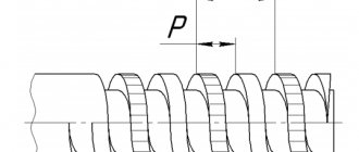
| P | — thread pitch; |
| r | — radius of curvature of the top and bottom of the profile of threaded pass-through gauges-plugs, gauge-rings and rollers of gauge-clips; |
| S | — deviation of the real position of the groove axis b3 relative to the nominal one (groove displacement); |
| TCP | — tolerance of the average diameter of the threaded control pass and no-go plug gauges, the threaded plug gauge for wear control and the installation plug gauge; |
| Td | — tolerance of the outer diameter of the external thread; |
| Td2 | — tolerance of the average diameter of the external thread; |
| TD1 | — tolerance of the internal diameter of the internal thread; |
| TD2 | — tolerance of the average diameter of the internal thread; |
| TP | — gauge thread pitch tolerance; |
| TPL | — tolerance of the average diameter of the threaded go and no-go gauges; |
| TR | — tolerance of the average diameter of the threaded pass and no-pass gauge rings; |
| Tα1 | — tolerance of the angle of inclination of the side side of the thread profile of a gauge with a full profile; |
| Tα2 | — tolerance for the angle of inclination of the side side of the thread profile of a gauge with a shortened profile; |
| u | - double the size of the cut of the top of the caliber thread; |
| W.G.O. | — the value of the average permissible wear of the threaded plug gauge and ring gauge; |
| WNG | — the value of the average permissible wear of non-go threaded plug gauges and ring gauges; |
| Z1 | — the distance from the middle of the tolerance field H1 of a smooth pass-through plug gauge to the pass-through (lower) limit of the internal diameter of the internal thread; the value of the average permissible wear of a smooth pass-through plug gauge; |
| Z2 | — the distance from the middle of the tolerance field H2 of a smooth pass-through ring gauge or clamp gauge to the pass-through (upper) limit of the outer diameter of the external thread; the value of the average permissible wear of a smooth pass-through ring gauge or a smooth pass-through clamp gauge; |
| ZPL | — the distance from the middle of the tolerance field TPL of the threaded pass-through gauge-plug to the pass-through (lower) limit of the average diameter of the internal thread; |
| ZR | — the distance from the middle of the tolerance field TR of the threaded pass-through ring gauge to the pass-through (upper) limit of the average diameter of the external thread. |
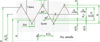
THREAD PROFILE AND LENGTH OF THE WORKING PART OF CALIBERS
3.1. Plug gauges of type PR (21) must have a full thread profile in accordance with that indicated in Figure 1a, ring gauges of type PR (1) and clamp gauges of type PR (7) - in accordance with that indicated in Figure 2a.
Damn.1
* Does not apply to caliber type PR (7).
Damn.2
3.2. The full thread profile of gauges of types PR (21), PR (1) and PR (7) must have a radius r at the tops and bottoms of the thread. The values of radii r related to the nominal thread profile must correspond to those indicated in Table 1.
Table 1
Dimensions in mm
| P | Number of steps per length 25.4 mm | b1, no more | u=0.14784P | r, no more |
| 0,907 | 28 | 0,20 | 0,134 | 0,125 |
| 1,337 | 19 | 0,30 | 0,198 | 0,184 |
| 1,814 | 14 | 0,40 | 0,268 | 0,249 |
| 2,309 | 11 | 0,50 | 0,341 | 0,317 |
Note. The radius r is the initial one for designing a thread-forming tool and is not subject to mandatory control.
3.3. It is allowed to produce plug gauges of type PR (21) with a profile in accordance with that indicated in Figure 1b, ring gauges of type PR (1) and clamp gauges of type PR (7) - in accordance with that indicated in Figure 2b, having vertices , cut along a chord passing through the tangent points of the circular arc of the rounded thread profile according to GOST 6357 by the value u/2 and with a groove width b1.
The numerical values of u and b1 must correspond to those indicated in Table 1. The value u is for reference, serves to calculate diameters at the thread tips and is not subject to direct control. The groove shape is arbitrary.
Note. The dimensions of the thread glands of products (the outer diameter of the internal thread and the internal diameter of the external thread) are not controlled by a gauge with a cut off top.
3.4. Plug gauges of the types KPR-PR (2), U-PR (8), U-NE (10), KNE-PR (12), KNE-NE (13) and KI-NE (16) must have a thread profile with cut off tops and with a radius r along the grooves of the thread in accordance with that indicated in Figure 3. The dimensions of the radii r must correspond to the values indicated in Table 1.
Notes:
1. The value of the cut of the thread tips is determined by the formulas for calculating the outer diameter of the gauges indicated in Table 9.
2. The dimensions of the thread recesses of the pass-through ring gauge type PR (1) are not controlled by the plug gauge type KPR-PR (2) with a cut off top.
Damn.3
3.5. Plug gauges of types KPR-NE (3), K-I (6) and HE (22) must have a shortened thread profile in accordance with that shown in Fig. 4, ring gauges of type HE (11) and clamp gauges of type HE (9) - in accordance with what is indicated in Figure 5.
Damn.4
* Does not apply to caliber type HE (9).
Damn.5
The shortened thread profile of the gauge must be made with groove b3 and dimensions F1 and F3 indicated in Table 2. The groove shape is arbitrary.
table 2
Dimensions in mm
| P | Number of steps per length 25.4 mm | F1=0.1P | b3 | F3 | |
| Nom. | Prev. off | ||||
| 0,907 | 28 | 0,091 | 0,25 | ±0,03 | From 0.20 to 0.35 |
| 1,337 | 19 | 0,134 | 0,40 | ±0,04 | 0,30 » 0,50 |
| 1,814 | 14 | 0,181 | 0,50 | ±0,05 | 0,40 » 0,70 |
| 2,309 | 11 | 0,231 | 0,80 | ±0,05 | 0,40 » 0,70 |
The F1 value is for reference; it is used to calculate the diameters at the thread tips of gauges with a shortened profile and is not subject to direct control.
3.6. The displacement S of the groove relative to the sides of the thread profile (Fig. 6) should be no more than the maximum deviation of the groove width b3 specified in Table 2.
1 - actual position of the groove axis; 2 - nominal position of the groove axis Figure 6
The maximum deviation of the groove width b3 can be increased by twice the difference between the limit and actual values of the displacement S, if the actual value is less than the limit.
Note. Instead of size b3 and offset S, it is possible to control the height F3 (Fig. 4).
3.7. The thread length of the working part of thread gauges must be no less than the values indicated in Table 3.
Table 3
| Designation (type number) of the caliber | Thread length of the working part of the caliber, mm |
| PR (1) | 0.8Nk |
| KPR-PR (2) | 0.8Nk+P |
| KPR-NOT (3) | 3P |
| K-I (6) | 3P |
| PR (7) | 0.8Nk |
| U-PR (8) | 0.8Nk+P |
| NOT (9) | In accordance with Table 9 and Figure 7 |
| U-NE (10) | 3P |
| NOT (11) | 3P |
| KNE-PR (12) | 3P |
| KNE-NE (13) | 3P |
| KI-NE (16) | 3P |
| PR (21) | 0.8Nk |
| NOT (22) | 3P |
Note. For make-up lengths L according to GOST 6357, the thread length of the working part of the pass-through gauges must be at least 0.8 of the make-up length of the thread.
Damn.7
3.8. The length of the working part of smooth gauges for monitoring the outer diameter of the external thread and the internal diameter of the internal thread must be no less than the values specified in Table 4.
Table 4
| Designation (type number) of the caliber | Length of the working part of the caliber, mm |
| PR (17) | 3P (for clamp gauge) |
| 0.8Nk (for ring gauge) | |
| NOT (18) | 3P |
| K-PR (19) | 3P |
| K-NOT (20) | 3P |
| PR (23) | 0.8Nk |
| NOT (24) | 3P |
| K-I (25) | 3P |