General information
The tip of the cutter, when moving at a constant feed speed along the rotating workpiece, cuts into, leaving a helical line on its surface (Fig. 4.42).
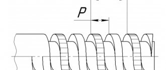
The inclination of the helix to the plane perpendicular to the axis of rotation of the workpiece depends on the rotation speed of the spindle with the workpiece and the feed of the cutter and is called the angle μ of the helix (Fig. 4.43). The distance between the helical lines, measured along the axis of the workpiece, is called the pitch P of the helical line. If a segment on the surface of a part equal to the pitch of the helix is turned onto a plane, then from the right triangle ABC we can determine
tgμ= P/(πd),
where d is the diameter of the workpiece along the outer surface of the thread.
When the cutter is deepened into the surface of the workpiece along the helical line, a helical surface is formed, the shape of which corresponds to the shape of the tip of the cutter. A thread is a helical surface formed on rotating bodies and used to connect, seal or ensure specified movements of machine parts and mechanisms. Threads are divided into cylindrical and conical.
Depending on the purpose of the threaded connection, threads of various profiles are used.
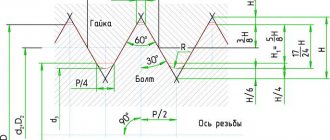
The thread profile is the contour of the thread section in a plane passing through its axis. Threads with acute-angled, trapezoidal and rectangular profiles are widely used.
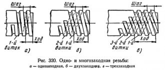
Threads are left and right. A screw with a right-hand thread is turned clockwise (from left to right), and a screw with a left-hand thread is turned counterclockwise (from right to left). There are single-start and multi-start threads. A single-start thread is formed by one continuous thread, and a multi-start thread is formed by several threads equidistantly located on the surface of the part. The number of threads is easy to determine at the end of the part, where the threaded surface begins (Fig. 4.44, a and b).
There are strokes Ph and pitch P of multi-start threads. The stroke of a multi-start thread (GOST 11708-82) is the distance along a line parallel to the thread axis between any initial midpoint on the side of the thread and the midpoint obtained by moving the initial midpoint along a helical line at an angle of 360° between the same points of one turn one thread of thread, measured parallel to the axis of the part. The stroke of a multi-start thread is equal to the thread pitch multiplied by the number of starts:
Ph= kP,
where k is the number of visits.
Thread cutting technology on lathes (article)
The tip of the cutter, when moving at a constant feed speed along the rotating workpiece, cuts into, leaving a helical line on its surface (Fig. 4.42).
The inclination of the helix to the plane perpendicular to the axis of rotation of the workpiece depends on the rotation speed of the spindle with the workpiece and the feed of the cutter and is called the angle μ of the helix (Fig. 4.43). The distance between the helical lines, measured along the axis of the workpiece, is called the pitch P of the helical line. If a segment on the surface of a part equal to the pitch of the helix is turned onto a plane, then from the right triangle ABC we can determine
tgμ= P/(πd),
where d is the diameter of the workpiece along the outer surface of the thread.
When the cutter is deepened into the surface of the workpiece along the helical line, a helical surface is formed, the shape of which corresponds to the shape of the tip of the cutter. A thread is a helical surface formed on rotating bodies and used to connect, seal or ensure specified movements of machine parts and mechanisms. Threads are divided into cylindrical and conical.
Depending on the purpose of the threaded connection, threads of various profiles are used.
The thread profile is the contour of the thread section in a plane passing through its axis. Threads with acute-angled, trapezoidal and rectangular profiles are widely used.
Threads are left and right. A screw with a right-hand thread is turned clockwise (from left to right), and a screw with a left-hand thread is turned counterclockwise (from right to left). There are single-start and multi-start threads. A single-start thread is formed by one continuous thread, and a multi-start thread is formed by several threads equidistantly located on the surface of the part. The number of threads is easy to determine at the end of the part, where the threaded surface begins (Fig. 4.44, a and b).
There are strokes Ph and pitch P of multi-start threads. The stroke of a multi-start thread (GOST 11708-82) is the distance along a line parallel to the thread axis between any initial midpoint on the side of the thread and the midpoint obtained by moving the initial midpoint along a helical line at an angle of 360° between the same points of one turn one thread of thread, measured parallel to the axis of the part. The stroke of a multi-start thread is equal to the thread pitch multiplied by the number of starts:
Ph= kP,
where k is the number of visits.
Thread cutting with die heads
Thread-cutting screw heads are used for cutting external and internal threads on lathes, turret lathes and automatic lathes.
Using a shank, the threading head is installed in the tailstock quill or in the turret of the machine. Radial, tangential and round combs are used in screw cutting heads. At the end of thread cutting, the dies automatically diverge and do not come into contact with the thread during the return stroke.
When cutting external threads, heads with round combs are widely used, since they are simple in design, allow for many regrinds and have greater durability than radial and tangential combs. The design and operating principle of existing screw-cutting heads have minor differences.
Internal threads are most often cut with threading heads with prismatic combs, the cutting edges of which are located at the same diameter and have a lead-in cone. The number of combs included depends on the size of the head. The combs are offset in the set one relative to the other in accordance with the angle of the helix of the thread being cut.
When cutting long screws and worms, cutting heads are used to increase productivity, which are mounted on the machine support. These heads are equipped with ordinary and cup cutters and are used for cutting external and internal threads.
Thread control
The thread pitch is measured with a thread template, which is plate 2 (Fig. 4.46), on which teeth are applied with a thread pitch indicated on the template plane. A set of templates for metric or inch threads is fastened into cassette 1. Thread templates are used to determine only the thread pitch.
The correctness of the internal and external threads made on a part is comprehensively assessed using thread gauges (Fig. 4.47). Thread gauges are divided into go-through gauges, which have a full thread profile and are, as it were, a prototype of a threaded connection part, and non-go-through gauges, which control only the average diameter of the thread and have a shortened profile.
To measure the outer, middle, inner diameters and thread pitch, thread micrometers are used (Fig. 4.48). A thread micrometer has mounting holes in the spindle and heel into which sets of replaceable inserts are installed that correspond to the thread elements being measured. For ease of measurement, a threaded micrometer is fixed in a stand and then adjusted according to a template or standard.
Before testing, the parts being tested must be cleaned of chips and dirt. During the inspection process, you should handle the gauges carefully so that nicks and scratches do not appear on their working threaded surface.
Thread cutting with cutters
On screw-cutting lathes, the most widely used method is cutting external and internal threads with cutters (Fig. 4.45). Threading cutters are rod, prismatic and round; their geometric parameters do not differ from the geometric parameters of shaped cutters. Triangular profile threads are cut with cutters with a leading angle at the apex ε = 60° ± 10′ for metric threads and ε = 55° ± 10′ for inch threads. Taking into account the errors in the movement of the caliper, which can lead to an increase in the thread angle, cutters with an angle ε = 59°30′ are sometimes used. The tip of the cutter can be rounded or chamfered (in accordance with the shape of the root of the thread being cut).
Threading cutters are equipped with plates made of high-speed steel and hard alloys. The part is first ground so that its outer diameter is smaller than the outer diameter of the thread being cut. For metric threads with a diameter of up to 30 mm, this difference is approximately 0.14 ... 0.28 mm, with a diameter of up to 48 mm - 0.17 ... 0.34 mm, with a diameter of up to 80 mm - 0.2 ... 0.4 mm. The reduction in the diameter of the workpiece is due to the fact that when cutting a thread, the material of the workpiece is deformed and, as a result, the outer diameter of the thread increases.
Threading in a hole is carried out either immediately after drilling (if high demands are not placed on the accuracy of the thread), or after boring it (for precise threads). Hole diameter (mm) for thread
d0 = dP,
where d is the outer diameter of the thread, mm; P — thread pitch, mm.
The diameter of the hole for the thread should be slightly larger than the internal diameter of the thread, since during the threading process the metal is deformed and, as a result, the diameter of the hole decreases. Therefore, the result obtained from the above formula is increased by 0.2...0.4 mm when cutting threads in viscous materials (steel, brass, etc.) and by 0.1...0.02 mm when cutting threads in brittle materials ( cast iron, bronze, etc.).
Depending on the requirements of the drawing, the thread may end with a groove for the cutter to exit. The internal diameter of the groove should be 0.1 ... 0.3 mm less than the internal diameter of the thread, and the width of the groove (mm)
b=(2…3)P.
In the process of cutting bolts, studs and some other parts, when the cutter is removed, as a rule, a thread run-out is formed.
For more convenient and accurate thread cutting, a shoulder 2...3 mm long is made at the end of the workpiece, the diameter of which is equal to the internal diameter of the thread. This shoulder is used to determine the last pass of the cutter; after threading is completed, the shoulder is cut off.
The accuracy of the thread largely depends on the correct installation of the cutter relative to the center line. In order to install the cutter along the bisector of the thread profile angle perpendicular to the axis of the workpiece, use a template, which is installed on the previously machined surface of the part along the line of the centers of the machine. The cutter profile is combined with the template profile and the correct installation of the cutter along the clearance is checked. Threading cutters should be installed strictly along the center line of the machine.
On screw-cutting lathes, threads are cut with cutters in several passes. After each pass, the cutter is retracted to its original position. Using the vernier of the lead screw of the transverse feed movement of the caliper, set the required cutting depth and repeat the pass. When cutting threads with pitches up to 2 mm, the feed is 0.05...0.2 mm per pass. If a thread is cut simultaneously with two cutting edges, the resulting chips become tangled and deteriorate the quality of the thread surface. Therefore, before the working pass, the cutter should be shifted by 0.1...0.15 mm alternately to the right or left, using the movement of the upper support, as a result of which processing is carried out with only one cutting edge. The number of roughing passes is 3...6, and finishing passes - 3.
Thread cutting by turning | 03/28/2012
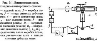
Turning is the most versatile method for producing threads, providing various types of threads in a wide range of diameters, pitches and processed materials. With this processing method, it is possible to achieve high accuracy of the relative position of the axis of the machined thread relative to other cylindrical and end surfaces of the part. The thread can be cut on any part of the part. It is possible to obtain threads with variable pitch. The workpiece is secured in the chuck or centers of the lathe, and the tool is mounted on a support, and it receives a feed movement to depth and along the axis. When cutting threads, the rotation of the workpiece and the tool feed along the axis are rigidly related to the size of the thread being cut, namely, the feed along the axis is equal to the pitch of the thread being cut.
Rice. 1 General diagram of thread cutting on a lathe Modern tools (mainly replaceable inserts) allow you to work at high speeds and feeds, which makes it possible to perform thread cutting operations with high productivity on CNC machines, according to standard thread processing cycles. The most widely used are multi-pass turning schemes, since in this case it is easiest to select optimal processing modes and operate the equipment in an automatic cycle, including on CNC machines. Dividing the total depth of cut into several passes increases process reliability and prevents overloading the tip of the threaded plate. To process the entire thread profile, about six passes are made. At the same time, with each subsequent pass it is recommended to reduce the plunge depth, because the length of contact between the tip of the cutting edge and the workpiece increases. Types of plunges There are three options for dividing the allowance and cutting to a new depth when turning a thread. The methods differ in the wear process, chip formation, and the quality of the machined thread. In practice, the choice of plunge method depends on the type of equipment, the material being processed, the pitch of the thread being cut and the geometry of the cutting insert. Radial plunge (Fig. 2. A) is the most common, and very often the only possible, method of thread cutting. The cutting into the workpiece follows a radius and chips are formed by both sides of the cutting tooth in the form of the letter V. Uniform wear occurs along the entire length of the cutting edge. The method is most preferable for small threads and materials that can be hardened by cutting (for example, stainless steels). When machining large threads there is a risk of vibration. Single-sided plunging (Figure 2.B) is the most preferred thread cutting method, and most CNC machines have this cycle as standard. The plate cuts into the workpiece at an angle less than the thread profile angle. The amount of axial movement between cuts can be calculated using the formula:
- 0.5*ap (radial feed) - for a thread profile angle of 60°. For an angle of 55°, the amount of axial movement is calculated using the formula:
- 0.42*ap (radial feed) - for a thread profile angle of 55°.
This allows you to obtain an infeed angle that is 5° less than half the thread profile angle (hereinafter referred to as the “infeed angle”). With this processing method, chip flow is controlled, and the cutting process itself is similar to simple turning. Less heat is generated at the tip of the plate, increasing process reliability and plate life. In addition, this method is less susceptible to vibration when processing large and also long threads. Lateral double entry (Fig. 2. C) is most often used for processing threads with large pitches and large profiles. The plunge direction changes for each subsequent pass until the entire thread profile is formed. The method ensures uniform wear of the cutting edge and greater durability. Its implementation requires special software on CNC machines.
Rice. 2 Plunge methods for turning Number of passes and plunge depth per pass For thread cutting, the number of passes and plunge depth are critical. For most machines, when writing a control program, it is necessary to specify the overall height of the thread profile and the plunge depth for the first or last pass. Recommendations for determining the number of passes and plunge depth:
- to ensure acceptable plate resistance Dworkpiece ≤ (Dmax.thread + 0.14 mm);
- the cutting depth should not be less than 0.05 mm;
- The cutting depth when processing austenitic stainless steel must be at least 0.08 mm.
It is especially important to follow the recommendations when working with multi-tooth inserts. To determine the number of passes, you can use lookup tables from cutting tool manufacturers' catalogs. The most suitable number of passes is determined practically. Formula for calculating the plunge depth per pass.
Ways to improve machining results 1. Gradually reducing the penetration depth = constant cross-sectional area of the chip, which is removed for each pass (Fig. 3a) Depending on the height of the thread profile, the initial penetration depth is 0.2-0.35 mm, then gradually decreases to 0. 09-0.02 mm. The last pass can be without plunging (cleaning) in order to eliminate errors associated with errors in the machine mechanisms. Cleaning passes are not recommended when using C geometry inserts because this can lead to deterioration of the chip formation process. The specified plunge depth ratio is most often used on modern CNC machines. 2. Constant plunge depth = best chip formation and long tool life (Fig. 3b). This method is popular for new generation machines. Because When the plunge depth is constant, the chip thickness is also constant and chip formation can be optimized. The initial value of the plunge depth should be 0.12-0.18 mm. The exact value depends on the cutting depth of the last pass, which must be at least 0.08 mm.
Attention!
- For tight thread tolerances, it is recommended to use a grinding pass with zero penetration value.
- For materials with high hardness, the number of passes should be increased.
- When cutting threads in materials that tend to harden during processing, for example, stainless steel, the cutting depth should not be less than 0.08 mm.
Types of Threaded Inserts Full Profile Inserts (High Performance Threading) This type of insert is the most widely used. They completely form the thread profile:
- the exact height of the thread is ensured, as well as the radii at the top and bottom of the profile, which guarantees the required thread strength;
- the plate processes the top of the thread profile;
- no precise pre-processing of the thread diameter is required;
- after cutting the thread there is no need to remove burrs;
- The allowance for the thread diameter should be 0.03-0.07 mm.
- Each profile and pitch requires a separate plate.
When processing materials that are subject to surface hardening by cutting, you should not choose too small penetration depths. Full profile inserts typically have a larger nose radius than partial profile inserts and require multiple passes when working with them.
Rice. 4 Full profile inserts Partial profile inserts (thread cutting with a minimum range of tools) This type of insert does not machine the top of the thread profile, so precise machining of the diameter of the rod / hole for external / internal threads is necessary, while:
- One insert can be used for a range of thread pitches with the same lead angle. — the number of wafers in stock is reduced.
- The universal use of an insert with a tip radius oriented to the smallest thread pitch leads to a decrease in tool life.
This is due to the fact that each thread profile must have its own plate radius.
Multi-tooth inserts (high productivity and cost-effective mass production threading) Inserts have two or more teeth and perform similarly to full profile inserts. The first or initial teeth of the plate have an incomplete, and the last tooth - the full height of the thread profile, in this case:
- the number of passes is reduced, which increases tool life, increases processing productivity and reduces costs;
- productivity increases by a multiple of the number of teeth on the cutting plate;
- more space is needed for the plate to exit the cutting zone, because the length of the working part has been increased;
- high rigidity of the AIDS system must be ensured, because cutting with multi-tooth inserts creates high cutting forces;
- These plates are only available for the most common profiles and thread pitches;
- It is necessary to pay special attention to compliance with the recommendations for cutting depth.
Rice. 5 Multi-tooth insert. How to control chip flow You can change the direction of chip flow by changing the cutting direction and plunge angle, which is especially important for cutting internal threads and threads with large pitches, when vibration and chip formation problems arise. The plunge angle should be 3-5° less than the thread profile angle in order to ensure good quality of the machined surface and avoid excessive wear of the cutting edges. Chip breaking during thread cutting Control of chip formation during thread cutting is a very important issue, because thread cutting is usually one of the last operations and the part cannot be damaged. Chip breaking is also important for automatic machines, when a person does not constantly monitor the processing. Drain chips can wrap around moving parts of the machine, damage already processed surfaces, get stuck in the conveyor, etc. Inserts with symmetrical geometry (type C) break chips well, their operating principle is similar to that of conventional turning inserts. The threading process is fully controlled, chip breaking, high quality finish and predictable edge life. Thin chips are formed, which easily curl in the desired direction. In order to ensure high quality processing on both sides of the thread profile, the last pass can be made with a radial plunge. Selecting a processing method and tool depending on the type of thread The method of cutting threads depends on the configuration of the part and the layout of the machine. Threading with feed in the direction of the chuck is the most common method. Machining from the chuck also occurs, for example, when a right-hand thread is made with a left-hand tool or vice versa. In this case, it is necessary to compensate for the negative lead angle of the thread by replacing the support plate. The advantage of using a right-hand cutter for right-hand threads and a left-hand cutter for left-hand threads is that it provides maximum support for the insert in the pocket and the cutting forces force the insert against the reference surfaces. However, under good machining conditions, reverse cutting direction is acceptable. The direction of feed when cutting threads, right or left, does not affect the correct production of the thread profile. When choosing a method, the direction of the cutting forces must be taken into account. It is desirable that they be directed inside the insert seat, especially when working with multi-tooth inserts. Turning internal threads Turning internal threads is not as widespread as turning external threads. Due to the cantilever mounting of the tool, it is difficult to cut long threads with a diameter of less than 20 mm. Turning of internal threads can be carried out using patterns similar to those used for external threads, as well as single-turn combs and multi-cutter self-closing heads. All teeth of a single-turn comb are located on an incomplete thread turn (profile cutting pattern); this allows the production of parts with a small thread run-out. Special cases of thread cutting Cutting threads of non-triangular profiles When cutting threads of a profile other than triangular, a significant increase in productivity is achieved by sequential multi-pass turning with several cutters of different profiles. Moreover, only the last finishing cutter has the full profile of the thread being cut. In this case, roughing and finishing strokes can be performed at different cutting speeds, and the tool can be changed manually or automatically. Turning of multi-start threads. After processing each helical groove, division into the next approach is carried out in three ways:
- The workpiece together with the spindle is rotated by 1/z of a turn with the lead screw stationary (z is the number of starts of the thread being cut);
- The cutter is shifted along the axis of the workpiece by the pitch of the screw being cut;
- The workpiece is rotated 1/z turn in the presence of a driving faceplate with precisely placed dividing grooves or a special chuck with a corresponding dividing scale.
In addition, all thread starts can be cut simultaneously by setting the appropriate number of cutters. The distance between the cutters in this case must exactly correspond to the pitch of the multi-start thread being cut. Productive single-pass turning of external threads with a self-opening multi-cutter head. In this case, the entire allowance is distributed between several simultaneously working cutters, which have an axial and radial displacement of each cutter relative to the previous one. The radial offset value corresponds to the radial feed of each cutter. All cutters are located in the head in one turn, which allows you to cut threads with a short run-out. The cutters can be equipped with quick-change, non-sharpenable inserts that are mechanically fastened. The working feed of the head is carried out from the machine lead screw. At the end of the working stroke, the cutters are automatically moved apart, and then the head returns to its original position at accelerated speed. The head can contain 5-12 cutters, depending on the diameter of the thread being processed. Single-pass cutting is significantly superior in productivity to multi-pass cutting with a cutter in an automatic cycle. List of sources Yakukhin V.G. "Making of threads." “Thread cutting. Sandvik Coromant Technical Manual. Table Practical tips for troubleshooting problems when cutting threads using the turning method.
Thread cutting with dies and taps
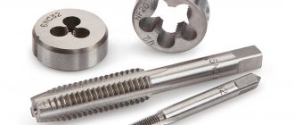
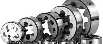
Dies are used to cut external threads on screws, bolts, studs and other parts. The area of the part where it is necessary to cut the thread with a die is pre-treated. The diameter of the machined surface should be slightly smaller than the outer diameter of the thread. For a metric thread with a diameter of 6...10 mm, this difference is 0.1...0.2 mm, with a diameter of 11...18 mm - 0.12...0.24 mm, with a diameter of 20...30 mm - 0.14...0.28 mm. To form a thread entry at the end of the part, it is necessary to remove a chamfer corresponding to the height of the thread profile.
The die is installed in a die holder (chuck), which is secured in the tailstock quill or turret socket. Cutting speed v when cutting threads with dies for steel workpieces is 3...4 m/min, for cast iron - 2...3 m/min and for brass - 10...15 m/min.
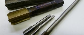
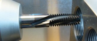
Internal metric threads with a diameter of up to 50 mm are often cut with taps. Typically, a lathe uses machine taps, which allows threads to be cut in one pass. For cutting threads in parts made of hard and viscous materials, sets consisting of two or three taps are used. In a set of two taps, the first (roughing) does 75% of the entire work, and the second (finishing) brings the thread to the required size. In a set of three taps, the first (rough) does 60% of the work, the second (semi-finish) - 30%, and the third (finish) - 10%. The taps in the set are distinguished by the intake part; the intake part of the rough tap has the greatest length.
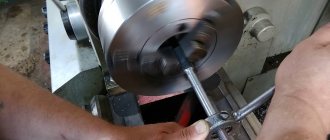
When installing a tap in a turret, a ring is put on its shank and secured with a screw, together with which the tap is installed in a chuck for dies and secured like a die.
Cutting speed v when cutting threads with taps for steel workpieces is 5... 12 m/min, for cast iron, bronze and aluminum - 6...22 m/min. Thread cutting is carried out with emulsion or oil cooling.
Thread cutting with die heads
Thread-cutting screw heads are used for cutting external and internal threads on lathes, turret lathes and automatic lathes.
Using a shank, the threading head is installed in the tailstock quill or in the turret of the machine. Radial, tangential and round combs are used in screw cutting heads. At the end of thread cutting, the dies automatically diverge and do not come into contact with the thread during the return stroke.
When cutting external threads, heads with round combs are widely used, since they are simple in design, allow for many regrinds and have greater durability than radial and tangential combs. The design and operating principle of existing screw-cutting heads have minor differences.
Internal threads are most often cut with threading heads with prismatic combs, the cutting edges of which are located at the same diameter and have a lead-in cone. The number of combs included depends on the size of the head. The combs are offset in the set one relative to the other in accordance with the angle of the helix of the thread being cut.
When cutting long screws and worms, cutting heads are used to increase productivity, which are mounted on the machine support. These heads are equipped with ordinary and cup cutters and are used for cutting external and internal threads.