GOST 14815-69*
Group G28
STATE STANDARD OF THE USSR UNION
SMOOTH PASSAGE PLUGS WITH NOZZLES WITH DIAMETERS OVER 50 TO 100 MM
Design and dimensions
Go plain plug gauges with headpieces of diameter over 50 to 100 mm. Design and dimensions
OKP 39 3111
Date of introduction 1971-01-01
By Decree of the Committee of Standards, Measures and Measuring Instruments under the Council of Ministers of the USSR dated July 7, 1969 N 771, the introduction date was set from 01/01/71 Verified in 1983. REPLACEMENT MN 4128-62 * REISSUE (August 1994) with Amendments N 2, 3, approved in February 1978, February 1984 (IUS 1-79, 6-84) This standard applies to smooth pass-through plug gauges designed to control holes with tolerance fields according to the EDSP CMEA and the OCT system. (Introduced additionally, Amendment No. 3).
Ring gauges, plug gauges and clamp gauges - their features and purpose
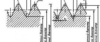
Threaded plug gauges have a one-piece design, complemented by inserts on a conical shank.
The tool consists of a threaded part, which is long, and a non-threaded part, which is short. The pass gauge has a full profile, the no pass gauge has from 3 to 5.5 turns in length. In addition, at the end of the non-pass part there is a cylindrical guide. The main task of these instruments is to measure the dimensions of products with the smallest average diameter. During operation, the plug gauge must be screwed into controlled rings. If the process occurs easily and freely, then the average diameter being checked is not less than the established specific size.
Ring gauges come in two types: they are rigid (non-adjustable) and adjustable. Non-adjustable gauges feature full-width threads, while adjustable gauges have a limited thread profile. In addition, the adjustable rings are equipped with rollers that allow you to adjust the degree of wear. One of the advantages of adjustable gauges is that they can be adjusted repeatedly, thereby increasing the wear resistance and longevity of the tool.
Non-adjustable ring gauges are used to control large product diameters and internal diameters of external threads. The outer diameter cannot be measured this way. Plug gauges can be used to check the degree of ring wear.
The most productive types of gauges are considered to be staples, which are most often used for measuring external threads. Such gauges are easily fixed directly to the product being measured and are quite easy to control and adjust when worn. Unfortunately, such instruments also have their drawbacks: they are easily deformed, leading to significant measurement errors.
How to use the tool
The rules for using such tools depend on their purpose. It is allowed to be used only in compliance with certain rules and the established accuracy class indicated in the marking. The use of plug gauges to control the accuracy of manufactured holes is allowed only with the help of a tool close to the parameters of the hole itself. The main condition for measurement accuracy is the free passage of the gauge insert through the hole being measured. Correct use of such devices requires compliance with the following rules:
- the passage side should enter the hole only under the influence of its own weight;
- It is prohibited to use additional methods of external influence (additional pressure, blows);
- Before checking, it is necessary to clean the parts from dirt and mechanical processing residues;
- Any type of lubricant that could affect the penetration of the gauge into the hole should be removed;
- the check must be carried out without rotating the meter relative to the part being examined;
- a prerequisite is compliance with the temperature regime (parts should be checked only at natural temperature);
- The frequency of inspections of the instrument itself and the rules for recording the results in established documents must be observed;
- each caliber must be stored in accordance with the established storage procedure (they should not come into contact with other metal parts or be exposed to external influences).
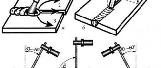
To control external threads, it is enough to apply the tool itself to the threads and determine the degree of coincidence. The internal thread is checked by screwing the head into a finished threaded hole. The process should be easy without effort or distortion.
To check the surface of the tapered shaft, use a suitable smooth tool. Quality is determined by the alignment of the surface of the part and the surface of the gauge. Comparison of the internal cone is made by immersing the nozzle into the prepared hole.
Calibers carry out operational control of product parameters of a large number of parts. This does not require special knowledge and skills in using complex metrological instruments. The operation is carried out promptly. You can compare several parameters at the same time.
Types of devices
The following types of calibers exist:
- Traffic jams.
- Staples.
- Probes.
- Cone gauges.
- To check the relative position of surfaces.
- For inspection of cylindrical threads.
Plug gauges
They are a rod with cylindrical elements at both ends. One of them has the largest maximum hole size and is called a no-go plug (NOT), and the second is the smallest and is called a go-through plug (PR). The no-go plug is noticeably shorter than the go-through plug, thanks to which the worker or inspector quickly and correctly determines the suitability of the parts.
Smooth plug gauges are made in composite parts, with steel or plastic handles in which inserts with conical shanks or cylindrical attachments are attached. To check holes in the range from 2 to 50 mm, conical shanks are made, and for holes in the range of 30-100 mm, cylindrical nozzles are made. If the insert is only on one side of the handle, then such plug gauges are called one-sided.
Gauge gauges
They are used to control shaft diameters; they are available in single-sided and double-sided designs. just as in the case of plugs, the PR bracket must pass, and the bracket must NOT pass along the shaft. Otherwise, the shaft is considered unusable, and the defect will be correctable only if it is necessary to remove excess metal to achieve the desired result.
When using brackets, under no circumstances should they be forced onto the shaft, as the bracket may “open up” and increase the distance between the measuring surfaces due to the compliance caused by its design. To prevent this, you should put the bracket on a horizontal shaft only under the influence of its own weight. At the same time, the shaft is also rotated, which at the same time allows one to check deviations from the round profile in the cross section.
Probe gauges
These are sets of steel plates with a thickness of 0.02 to 1 mm and a length of 100 or 200 mm. They are used to control the size of the gap between surfaces when assembling various mechanisms. In this case, one or more probes in a set are inserted into the gap to select the desired value.
When using probes, it is important to follow certain rules:
- when measuring, the probe should move smoothly with little effort, and not fall freely;
- For smooth movement of the plates, it is recommended to lightly lubricate them;
- Do not apply much force to the probe so as not to damage it;
- The size of the gap is determined by summing the thicknesses of all the probes from the set that are completely included in the gap.
Cone gauges
Serve for testing conical surfaces, such as instrument cones. Using a ring gauge, the suitability of the outer surfaces is checked, and with a stopper, the suitability of the internal surfaces is checked. A part is considered suitable if its end is located in the area between the marks or between the planes of the ledge. This distance is equal to the tolerance.
Gauges for checking the location of surfaces
There can be a variety of designs. With their help they control:
- coaxiality of two or more holes, as well as shaft journals;
- distances between the axes of the holes;
- parallelism, perpendicularity or amount of inclination of surfaces or axes;
- distance between the hole axis and the plane;
- the depth of various grooves and ledges.
Gauges for inspection of cylindrical threads
Used for a comprehensive check of the average diameter, profile angle, as well as the largest internal diameter of the external thread or the smallest external diameter of the internal thread. Using these devices, metric, inch, trapezoidal, thrust and round threads with a diameter of 1 to 600 mm are checked.
The control set consists of working go-through (PR) and non-go-through (NOT) gauges, as well as control ones, which are used to check working ring gauges and plugs.
Go-through gauges must screw freely into the controlled thread, while non-go-through gauges must not screw into it. It is allowed to screw on non-go gauges up to 2 turns, and the number of turns is determined when unscrewing the gauge and the controlled product. If the thread of the part being tested is short (less than 3 turns), then screwing on a non-go gauge is not allowed.
The PR thread gauge has a length of about 80% of the make-up length, that is, the length of contact between the bolt and nut threads, measured along their axis.
For a non-passable one, the length is at least 3 turns.
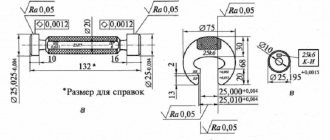
Smooth double-sided plugs for checking the internal diameter of the internal thread design
Description
Design and dimensions GOST 14807-69
Tolerance fields:
- GOST 24853-81
Purpose: smooth double-sided gauges with full and incomplete profiles, designed to control holes with tolerance fields according to the ESDP CMEA and according to the OST system
Types of thread gauges:
- PR - passage plugs
- NOT - impassable plugs
Examples of ordering designations:
- Stopper Ø 10 PR N7
- Stopper Ø 130 HE H12
Thread gauges are designed to control the average diameter of a thread. External threads are checked with threaded rings, internal threads with threaded plugs.
A threaded plug gauge can be structurally made either with two threads at different ends of the gauge (on one side there is a through part, on the other side there is a non-go through part, or only with a through thread on one side of the gauge.
A thread ring gauge is designed to control the outer diameter of a thread.
The threaded ring gauge is made as a set - PR pass and NOT pass, which allows control within the thread tolerance range. Can be supplied individually.
Helpful information:
Table of thread pitches for main and small metric threads GOST 8724-81
| Diameter | Thread pitch P, mm | |||
| Basic step | Small step 1 | Small step 2 | Small step 3 | |
| M1 | 0.25 | — | — | — |
| M1.2 | 0.25 | — | — | — |
| M1.4 | 0.3 | — | — | — |
| M1.6 | 0.35 | — | — | — |
| M1.8 | 0.35 | — | — | — |
| M4 | 0.7 | 0.5 | — | — |
| M5 | 0.8 | 0.5 | — | — |
| M6 | 1 | 0.75 | 0.5 | — |
| M8 | 1.25 | 1 | 0.75 | 0.5 |
| M10 | 1.5 | 1.25 | 1 | 0.75 |
| M12 | 1.75 | 1.5 | 1.25 | 1 |
| M14 | 2 | 1.5 | 1.25 | 1 |
| M16 | 2 | 1.5 | — | 1 |
| M18 | 2.5 | 2 | 1.25 | 1 |
| M20 | 2.5 | 2 | 1.25 | 1 |
| M22 | 2.5 | 2 | 1.5 | 1 |
| M24 | 3 | 2 | 1.5 | 1 |
| M27 | 3 | 2 | 1.5 | 1 |
| M30 | 3.5 | 2 | 1.5 | 1 |
| M33 | 3.5 | 2 | 1.5 | — |
| M36 | 4 | 3 | 2 | 1.5 |
| M39 | 4 | 3 | 2 | 1.5 |
| M42 | 4.5 | 3 | 2 | 1.5 |
| M45 | 4.5 | 3 | 2 | 1.5 |
| M48 | 5 | 3 | 2 | 1.5 |
| M52 | 5 | 4 | 2 | 1.5 |
| M56 | 5.5 | 4 | 3 | 1.5 |
| M60 | 5.5 | 4 | 3 | 1.5 |
| M64 | 6 | 4 | 3 | 2 |
| M68 | 6 | 4 | 3 | 2 |
Tolerance fields for external and internal threads established in accuracy classes for metric threads GOST 16093-2004
| Accuracy class | Make-up length | |||||||||
| S "short" | N "normal" | L "long" | ||||||||
| Tolerance field of external threads (rings, control plugs) | ||||||||||
| Accurate | — | (3h4h) | — | — | — | (4g) | 4h | — | — | (5h4h) |
| Average | 5g6g | (5h4h) | (6d) | 6e | 6f | 6g | 6h | (7e6e) | 7g6g | (7h6h) |
| Rude | — | — | — | (8e) | — | 8g | — | (9e8e) | (9g3g) | |
| Accuracy class | Make-up length | |||||
| S "short" | N "normal" | L "long" | ||||
| Tolerance field of internal thread (working plugs) | ||||||
| Accurate | — | 4H | — | 5H | — | 6H |
| Average | (5G) | 5H | 6G | 6H | (7G) | 7H |
| Rude | — | — | (7G) | 7H | (3G) | 8H |
Tolerance fields in bold are intended to be selected first.
Tolerance fields for external and internal threads established in accuracy classes for trapezoidal threads GOST 9562-81
| Accuracy class | External thread (rings) | Internal thread (plugs) | ||
| Make-up length | ||||
| N | L | N | L | |
| Tolerance field | ||||
| Accurate | 6e; 6g | 7e | 6H | 7H |
| Average | 7e; 7g | 8e | 7H | 8H |
| Rude | 8c; 8e | 9c | 8H | 9H |
Types of gauges for cylindrical threads. GOST 24939-81
Working thread gauges for cylindrical threads are supplied as a set and consist of two pieces: “go” PR and “no go” NOT.
PR - controls the largest average diameter (reduced average diameter) and, at the same time, the largest internal diameter of the thread;
NOT - controls the smallest average thread diameter. The caliber can be screwed on up to two turns.
To control external threads, ring gauges are used, and plug gauges are used to control internal threads. Sometimes plugs are called “inserts”, in fact they are the same thing, “insert” is PR or NOT without a handle. The plugs are manufactured as a set on one handle PR and NOT in the form of a “dumbbell” for diameters up to 50 mm; also, at the request of the customer, they can be made individually in a separate package.
The production of working rings is not possible without the use of the following counter gauges:
KPR-PR - the gauge must be freely screwed into the controlled ring gauge. The screwability of a plug gauge with a ring gauge means that the given average diameter of the ring gauge is not less than the established smallest limit size, and the outer diameter of the ring gauge is not less than the largest outer diameter of the external thread.
KPR-NOT - the gauge controls the largest average diameter of the ring gauge. The gauge must not be screwed into the controlled ring gauge. Screwing in up to one turn on each side of the ring gauge is allowed.
KNE-PR - The gauge controls the smallest average diameter (reduced average diameter) of the ring gauge. The gauge must screw freely into the controlled ring gauge. The screwability of a plug gauge with a ring gauge means that the given average diameter of the ring gauge is not less than the established smallest limit size
KNE-NE - The gauge controls the largest average diameter of the ring gauge. The gauge must not be screwed into the controlled ring gauge. Screwing in up to one turn on each side of the ring gauge is allowed.
All of these gauges are designed to test new impeller rings only and are typically only used by the gauge manufacturer. Using these gauges for incoming inspection of batches of rings from another manufacturer is incorrect, because in case the average diameter of the counter gauges is actually within different limits of the tolerance field, it can lead to non-make-up. Control using “native” control plugs is optimal. Currently, production does not store a batch of technological counter gauges KPR-PR, KPR-NE, KNE-PR and KNE-NE for a long time and, as the cast iron laps wear out, they grind the control plugs to a smaller diameter and produce new ones when the next order is received.
During operation, the working ring gauges are ground down, which leads to an increase in their diameters; to check whether the size exceeds the tolerance limit, wear control plugs are used:
CI - used to check the pass ring PR. The gauge must not be screwed into the controlled ring gauge. Screwing in up to two turns on each side is allowed.
KI-NOT – used to check the non-go ring NOT. The gauge must not be screwed into the controlled ring gauge. Screwing in up to two turns on each side is allowed.
If the wear control plug KI or KI-NE is screwed in more than two turns, the ring is considered worn out and is not subject to further use.
There are no control thread gauges; universal control methods are used to check the external threads of working plugs.
All calibers are made of structural bearing steel ШХ15 (GCr15), hardness HRC 58…62.
| Smooth double-sided plugs for checking the internal diameter of the internal thread design in accordance with GOST 14807 (up to 6 mm), 14810-69 (over 6 mm) tolerances in accordance with GOST 24853-81. |
Power tool caliber and additional classifications
In addition to the main classification, there is another one. In it, these adaptations are extreme and normal. Limit gauges are used where not only reliable, but also durable connection of parts is required. With the help of such gauges, you can find out whether the size of the part under control corresponds to the permissible limits or whether it is much greater. By normal calibers we mean particularly precise templates. They are usually used when it is necessary to control complex elements and profiles.
Another classification can be considered, due to recent developments that have given the world electrically driven calibers, and they really appeared not so long ago. They are mainly used in large enterprises where it is necessary to quickly and efficiently control a large number of parts. Electrical wires and a mechanism are installed at the ends of the tool, which carries out the screwing itself. The power tool has a caliber and a special regulator, which itself takes readings and compares the obtained dimensions with acceptable ones. When using this tool, you need to read the instructions.
General information and classification of calibers
It should be said right away that gauges do not allow one to completely accurately determine the geometric size of a product; the tool is intended to establish compliance of the part parameters with the dimensions indicated in the drawing. In other words, gauges are used to determine tolerances when manufacturing a part.
Many automakers and builders use this tool to sort parts. Despite the simplicity of the caliber design, it can be used to quickly and easily control a product of even the most complex configuration. True, the tool also has some disadvantages - insufficient versatility and the inability to detect significant deviations in size.
Depending on the type and purpose, calibers are divided into:
- plug gauge;
- ring gauge;
- clamp gauge.
Also, the instrument is usually divided into extreme and normal. Limit gauges have two main parameters, one of which corresponds to the maximum (pass) size of the part, the second – to the minimum (no pass). Normal gauges include the size required for a particular part.
Limit type tools are used more often; normal gauges are usually used as control gauges. In addition, extreme calibers are easy to use without special skills, and the operation of a normal tool requires a high level of professionalism.
The gauges used to carry out control measurements and determine the shape of the part at the initial stage are called working gauges, and those used to control threads are called counter-gauge gauges. There are also receiving gauges used to determine the quality of manufactured products.
Depending on the purpose, there are also several options for the tool. For external threads, threaded ring gauges are used, counter-plug gauges are used for conical rings, for smooth rings, smooth conical plug gauges or conical counter-plug gauges are suitable. Internal threads are measured using smooth or threaded cone plug gauges.
Basic requirements for calibers
The main requirements for all calibers are set out in the technical documentation for their manufacture. These requirements are given in various GOSTs. They can be divided into the following categories:
- the correct choice of metal for the production of measuring attachments (high rigidity must be ensured, which prevents the slightest deformation during storage and operation);
- the arrangement of working elements (nozzles, plates, washers) must be carried out with a high degree of accuracy above the measured parameters;
- ensuring durability and wear resistance (this is ensured by the use of high-alloy tool steels and special alloys);
- high anti-corrosion resistance (use of special methods for processing calibers and resistant coatings);
- creation of a system of periodic metrological control (checks must be carried out in accordance with the established frequency and the results must be recorded in the appropriate journal);
- calibration of calibers must be carried out on equipment with a higher accuracy class than the caliber itself;
- strict adherence to the established labeling system with precise indication of all necessary parameters.
For example, the requirements for smooth plug gauges are set out in GOST 14810-69. This standard systematizes not only all requirements, but also defines all permissible parameters of these measuring instruments.
Other types of calibers
The variety of problems that need to be solved during the mass production of parts made using mechanical processing required the creation of a wide range of measuring tools. They must quickly and accurately confirm the class of the treated surface or compliance with technological standards. Classification of calibers is necessary to accurately determine the purpose of the measuring unit and its scope of application. The following types of calibers are used in modern production:
- plug gauges;
- staple-gauge;
- probes;
- cone-shaped calibers;
- for checking cut threads;
- precision surface treatment;
- profile templates;
- checking the relative position of the surface.
All types of smooth plugs for assessing the accuracy of cylindrical holes are manufactured in accordance with GOST 24851-81. Standardization of these devices is specified in ISO-R1938-1971. This document approves the labeling and name of each class.
They are made single-sided and double-sided. In terms of measuring capabilities, they are single-limit and double-limit. The first type is made of two types, passable and non-passable, each of which has the corresponding designation PR - passable and NOT - non-passable. For a control instrument, I add the letter K, for example, K-PR, which means control pass. The manufacturing method depends on the scale of production of the main parts. If products are produced in small series, alloy metal sheets are used to produce tools; in large-scale production, casting or forging methods are used.
Using cone nozzles, the shape of conical surfaces is monitored. They are used to check conical shanks, holes, and other gauges. Devices for monitoring the relative position of surfaces are quite diverse. They can be manufactured individually for each of the manufactured parts. They are used to compare the parallelism of closely spaced surfaces, the alignment of holes, and the symmetry of grooves located on shafts or bushings.
The shape and size of threaded products depends on the type and parameters of the cut thread (its pitch, diameter and length). These tools come in two types: adjustable and non-adjustable. The former have the ability to adjust individual instrument parameters.
Profile structures include all types of templates designed to control compliance with the accuracy of a complex surface shape. The main method for checking the finished product is the so-called “light slit” method. It clearly shows the non-compliance of the manufactured shaped surface with the established requirements.
Purpose of calibers
Gauges are one of the first measuring instruments that are used in the production of mating parts (shaft and bushing, screw and nut, etc.). This area of application gave rise to the concept of interchangeability by occurrence. In this case, one caliber was made as an exact copy of a part from a pair, and the second part from the same pair was adjusted to it. However, this method of verification was inaccurate, since the size match was determined subjectively, by eye.
With the growth of mass production, the concept of interchangeability was born. It reflected the principle of producing parts that, when randomly combined within two limits, formed a functioning unit. The difference between the two maximum sizes is called tolerance. In this case, the size corresponding to the maximum was called the passing limit, and the second, corresponding to the minimum, was called the non-passing limit.
The introduction of the concept of tolerance and an expanded classification of limiting calibers made it possible to objectively assess the quality of parts, sorting them into good and bad (defects). For production control, regulatory documents were developed that covered a wide range of limit gauges and designated the sizes and exact characteristics of their varieties (plug gauges, clamp gauges, bushing gauges), which were used to control shafts, holes, cones and threaded connections.
Over time, gauges were replaced by pneumatic and later electronic measuring instruments and control devices. So, at present, limit gauges are used to check only those parts whose size control is difficult: shafts and small-diameter holes, threaded parts, etc.
Design
The device of the plug gauge is regulated by the provisions of GOST 14807-69, GOST 24851-81, GOST 17758-72 and GOST 14810-69. These standards apply accordingly to:
- A smooth double-sided tool equipped with inserts with a diameter of 1...6 mm.
- A smooth double-sided tool, with inserts having a diameter of more than 3 (and up to 50 inclusive) mm.
- Threads of appropriate accuracy classes.
The plug gauge consists of:
- A handle that has the cross-sectional shape of a circle with a fairly wide flat, designed to securely hold the tool in the hand.
- Go-through measuring pin (with thread - for threaded gauge plugs).
- No-go measuring pin.
- Two locking inserts that hold the pins in place.
The plug gauge in accordance with GOST 14810-69 has a similar design, but for ease of holding, the surface of the handle is made with continuous corrugations. The handle can be designed in the form of a hexagon.
One of the ends of the measuring pin is made flat (near it there is a through groove into which the fixing insert fits). The second end has a chamfer, which makes it easier for the pin to enter the cavity being measured.
The symbol for plug gauges includes two groups of numbers with 4 characters in each group. The marking also indicates the size of the tolerance field that can be controlled using this plug gauge.
Handles are made of plastic (for tools with pins up to 3 mm) or metal. For the manufacture of pins, alloyed tool steels are used in accordance with GOST 5950-73, which are characterized by the smallest size fluctuations depending on external conditions of temperature and humidity.
Smooth plug gauges GOST 24851-81 are designed according to a similar principle, intended for estimating the dimensions of external surfaces, for example, shafts.
Features of calculating thread gauges
When designing thread gauges, the following indicators are taken into account:
- step;
- controlled thread tolerance fields;
- make-up length;
- external nominal cross-section.
To calculate metric threads, the nominal internal and average cross-section of the connection is taken into account. For trapezoidal threads, the diameters of the nut (internal and external) and screw (internal) are also taken into account.
The specific shape of the gauge is selected depending on the type of tool.
In modern production, caliber calculations are carried out using special programs.
Basic requirements for calibers
Regardless of the type and purpose, any caliber must meet certain requirements:
- Manufacturing accuracy - the working dimensions of the tool must correspond to the manufacturing tolerances established.
- High rigidity with low weight is necessary to reduce errors in the deformation of gauges (especially large staples) during measurement. Light weight makes it possible to increase the sensitivity of control of medium and large sizes.
- Wear resistance - this indicator is necessary to ensure minimal costs for the manufacture and periodic checking of calibers. For this purpose, the working surface of the tool is made of alloy steel, which is subsequently hardened to increased hardness and chrome-plated.
- The optimal design of the gauges ensures high performance when performing measurements.
- Incorporating heat treatment into the production stage allows for stable tool dimensions to be achieved.
- Anti-corrosion properties are extremely important for the safety of calibers.
Calibers, their properties
A special means of controlling one or more dimensions, as well as the shape and relative position of the surfaces being processed is called a gauge. Their main difference from universal measuring instruments is that calibers do not have a scale, since they are designed to control one parameter or a complex of them. For example, using a caliper or micrometer, you can measure the actual diameter of the shaft and compare it with that indicated on the drawing. This is exactly what they do in single or small-scale production.
But in the circumstances of serial and mass production, this is not economically feasible, because when measuring with universal means, when accuracy of the order of hundredths and thousandths of a millimeter is required, the control results depend on the qualifications of the worker. High skill implies an appropriate salary, and the time spent on the control process increases. These factors increase the cost of production.
Advantages of calibers:
- ease of use allows the use of low-skilled workers and supervisors;
- speed of control;
- the ability to simultaneously check several parameters.
Flaws:
- limited applicability;
- inability to determine numerical deviations in dimensions.
Requirements for manufacturing and operation
The following conditions apply to all calibers, regardless of their purpose and type:
- High accuracy of positioning of working surfaces. Tolerances for the manufacture of calibers are significantly smaller than the permissible deviations of controlled products.
- Rigidity that does not allow deformation during measurement. Mainly concerns large-sized staples.
- Good wear resistance, reduces the cost of manufacturing and checking calibers. Measuring elements are made from alloy steel grades X, ShKh15, tool steels U10A, U12A, as well as hard alloys.
- Corrosion resistance through the use of special coatings.
- Mandatory marking of calibers indicating the nominal size and its maximum deviations.
Since calibers are an expensive and important instrument, it is recommended to strictly follow certain rules when working with them:
- Do not apply force or shock to the caliber under any circumstances;
- tested surfaces must be clean, dry and free of burrs;
- when checking a part, it is prohibited to rotate it;
- It is impossible to control hot or warm products, since this changes their dimensions and the calibers wear out faster;
- strictly adhere to the deadlines for control checks.
During storage, the working surfaces of the calibers should not come into contact with metal objects.
Basic classifications of calibers according to GOST 27284-87
Let us tell you in more detail about the types of calibers, which differ according to the type of product being controlled.
Gauge plugs for checking holes
The names and characteristics of plug gauges are listed in GOST 14807-69 and GOST 14827-69. These include:
- double-sided plugs with cylindrical inserts;
- double-sided plugs with inserts and tapered shank;
- plugs with cylindrical nozzles;
- full and incomplete traffic jams;
- one-way leaf plugs;
- incomplete and full washers.
Gauge gauges for checking medium and large shafts and holes (diameter 30–500 mm) are made to order, one piece at a time. And for measuring small holes with a diameter of 0.5–10 mm, ready-made sets of universal plug gauges are designed in increments of 0.1; 1.0; 2.0 and 10.0 µm. The tolerance on the diameter is ±0.4 µm, and the length of the working part of the plugs is 0.1–50 mm.
Main types of gauge plugs
Small sets of 2–3 precise gauges allow you not only to sort parts into good and defective ones, but also to quite accurately determine their diameters. The accuracy of measuring small diameters with gauges is higher than that of large ones. In this case, there is practically no temperature error, and the error from the tolerance for caliber manufacturing can be neglected.
Gauge clamps for shaft inspection
The main parameters and types of staple gauges are given in GOST 18358-93 and GOST 18360-93. The following types of staples are distinguished:
- single-sided sheets;
- sheet double-sided;
- stamped one-sided;
- stamped double-sided;
- single-sided with handle.
Main types of staple gauges
Adjustable gauges compensate for wear and can be adjusted to different sizes. However, they have lower measurement accuracy and are therefore used to control dimensions with tolerances no more precise than 8th grade accuracy.
Adjustable gauge