Description
Tapered pipe threads have a similar profile to cylindrical threads, but differ in the reduction in diameter from the beginning of the thread to the end of the part. The taper is done in a ratio of 1:16.
Kinds:
- inch conical (profile angle 600);
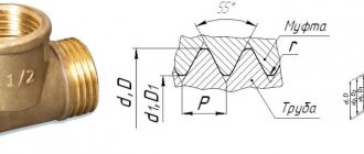
- metric conical (profile angle 550);
- pipe conical (angle similar to metric).
Creating inch conical-cylindrical joints is not possible. Therefore, inch ones are in demand only for solving specific problems.
When screwing on the nut, the seal is achieved due to the tight fit of the cut grooves due to the increase in diameter from the end to the middle of the part. Therefore, it is used in high pressure pipelines.
PROFILE
1. PROFILE
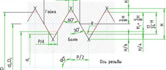
1.1. The nominal profile of the metric tapered thread (external and internal) must correspond to that indicated in Figure 1.
Damn.1. Nominal profile of metric tapered threads (male and female)
Taper 1:16; 3°34'48"; 1°47'24" - outer diameter of the external tapered thread; — outer diameter of the internal tapered thread; - average diameter of external tapered thread; - average diameter of internal tapered thread; — internal diameter of the external tapered thread; — internal diameter of the internal tapered thread; - cone angle; — slope angle; — thread pitch; - height of the original triangle Figure 1
The profile of the internal cylindrical thread connected to the external conical thread must have a flat-cut cavity. Note. In the absence of special requirements for density or when using seals to achieve tightness of a threaded connection, the shape of the cavity of conical (external and internal) and cylindrical (internal) threads is not regulated.
1.2. The dimensions of the profile elements of conical and cylindrical threads are in accordance with GOST 9150-81.
Characteristics
Main characteristics:
- sizes - from 1/16' to 6';
- number of turns per inch - from 11 to 28 depending on the diameter;
- pitch - from 0.8 to 2.309 mm;
- the outer diameter is 9.729–33.250 mm, and the inner diameter is 8.567–30.292 mm;
- the cutting pitch is determined from reference data depending on the diameter;
- the angle of inclination of the sides of the cone relative to the center line of the part should have a ratio of 1:16;
- welding machines are used for flanges only with a diameter of more than an inch;
- It is necessary to maintain the ratio of the total length and cutting distance.
1. PROFILE
1. PROFILE
1.1. The nominal profile of the metric tapered thread (external and internal) must correspond to that indicated in Figure 1.
Damn.1. Nominal profile of metric tapered threads (male and female)
Taper 1:16; 3°34'48"; 1°47'24"
— outer diameter of the external tapered thread; — outer diameter of the internal tapered thread; - average diameter of external tapered thread; - average diameter of internal tapered thread; — internal diameter of the external tapered thread; — internal diameter of the internal tapered thread; - cone angle; — slope angle; — thread pitch; - height of the original triangle
Damn.1
The profile of the internal cylindrical thread connected to the external conical thread must have a flat-cut cavity. Note. In the absence of special requirements for density or when using seals to achieve tightness of a threaded connection, the shape of the cavity of conical (external and internal) and cylindrical (internal) threads is not regulated.
1.2. The dimensions of the profile elements of conical and cylindrical threads are in accordance with GOST 9150-81.
GOST requirements
Basic requirements of GOST 6111-52:
- the deviation of the axis of the base plane to the nominal diameter should not exceed the thread pitch;
- the position of the base plane is specified by the distance from the end of the workpiece;
- the diameters of the tapered thread are located in a single main plane and are determined by the design section;
- the length of the external thread l2 is determined based on checking the average diameter with a corresponding ring gauge, and the external thread - with a plug;
- when screwing on pipes and couplings of nominal sizes, the plane of the thread must coincide with the end part of the coupling;
- the number of turns on the large diameter of the cone should not be less than two;
- the length from the base plane to the end of the tube can be reduced, but still meet other requirements of the standard;
- the generatrices of the cone with the center line should make an angle of 1047'24”.
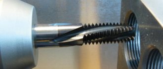
Conical thread according to GOST (Photo: Instagram / metall_detal)
Requirements GOST 6211-81
The values of the average d2 and internal d1 diameters must be calculated using the formulas:
d2=d-0.640327•P;
d1=d-1.280654•P;
where d is the outer diameter;
P - step.
- the length of the internal thread should be 0.8(l1-Δ1l2), where Δ1l2 are the values indicated in Table 2, GOST 6211-81;
- the distance of screwing the external thread onto the internal thread should be l1+Δ1l2;
- the displacement of the base plane is a total value determined by the pitch, the angle of inclination of the profile, the angle of the cone, the average diameter;
- Tolerances for the average diameter are indicated in Table 3, GOST 6211-81.
Metric thread parameters and parts
Metric thread has the following parameters and parts.
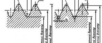
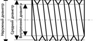
- Diameter. External - D and d. Internal - D1 and d1. Medium - D2 and d2. The outer diameter is called nominal and is used in markings and designations in drawings.
- Step. Determined by the distance between two vertices. Denoted by the letter P.
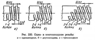
- Stroke (Ph). In a single-start metric thread, the lead is equal to the pitch. In a multi-start thread, the stroke is determined by the product of the pitch and the number of starts.
Image No. 3: thread stroke and pitch
- Chamfer. This is a surface with an inclination angle of 45°, located in front of the beginning of the screw part.
- Escape. This is the transition point to the smooth part of the part.
The run-off, the section with turns and the chamfer form the total length of the thread.
Tolerance fields for metric threads
The quality and reliability of connections depend on the accuracy of the parameters of external and internal metric threads. For clear standardization, the tolerances specified in GOST 16093-2004 are used.
Tolerance fields are set in three accuracy classes.
- Rude. There are serious deviations. They occur, for example, when cutting metric threads on hot-woven rods and in deep blind holes.
- Average. Tolerances of this class are used when forming metric threads in most cases.
- Accurate. Using tolerances of this class, precision metric threads are formed. High precision parameters ensure the most reliable fit with a minimum of vibrations.
Image No. 4: tolerance fields for external and internal threads
Designation on drawings
Designation of pipe tapered thread:
- R - external conical;
- RC - conical grooves of internal type;
- RP - internal conical with a cylindrical profile;
- LH - left;
- RH - right;
- MK - conical metric;
- M - metric;
- K - inch conical;
- reproach. — shortened profile;
- pov exact — increased cutting accuracy.
In the drawing, the designation is placed using a leader on the shelf, the arrow points to the main line. Cutting lengths are not indicated as this is standard. Tapered threads are indicated as a fraction: the numerator is the marking of the internal thread, and the denominator is the external thread.
The main plane of the thread is indicated by a solid thin line.
2. DIAMETERS, STEPS AND BASIC DIMENSIONS
2.1. Diameters, pitches, nominal values of the main dimensions of conical (external and internal) threads must correspond to those indicated in Figure 2 and Table 1.
Damn.2. Diameters, pitches, nominal values of the main dimensions of conical (external and internal) threads
— working thread length; — length of the external thread from the end to the main plane; — length of the internal thread from the end to the main plane
Damn.2
Table 1
mm
| Nominal thread diameter | Thread diameters in the main plane | Thread length | |||||
| 1st row | 2nd row | ||||||
| 6 | 1 | 6,000 | 5,350 | 4,917 | 8 | 2,5 | 3 |
| 8 | 8,000 | 7,350 | 6,917 | ||||
| 10 | 10,000 | 9,350 | 8,917 | ||||
| 12 | 1,5 | 12,000 | 11,026 | 10,376 | 11 | 3,5 | 4 |
| 14 | 14,000 | 13,026 | 12,376 | ||||
| 16 | 16,000 | 15,026 | 14,376 | ||||
| 18 | 18,000 | 17,026 | 16,376 | ||||
| 20 | 20,000 | 19,026 | 18,376 | ||||
| 22 | 22,000 | 21,026 | 20,376 | ||||
| 24 | 24,000 | 23,026 | 22,376 | ||||
| 27 | 2 | 27,000 | 25,701 | 24,835 | 16 | 5 | 6 |
| 30 | 30,000 | 28,701 | 27,835 | ||||
| 33 | 33,000 | 31,701 | 30,835 | ||||
| 36 | 36,000 | 34,701 | 33,835 | ||||
| 39 | 39,000 | 37,701 | 36,835 | ||||
| 42 | 42,000 | 40,701 | 39,835 | ||||
| 45 | 45,000 | 43,701 | 42,835 | ||||
| 48 | 48,000 | 46,701 | 45,835 | ||||
| 52 | 52,000 | 50,701 | 49,835 | ||||
| 56 | 56,000 | 54,701 | 53,835 | ||||
| 60 | 60,000 | 58,701 | 57,835 | ||||
Note. Shorter thread lengths may be used. When choosing thread diameters, the first row should be preferred to the second.
2.2. The diameters, pitches, nominal values of the outer, middle and inner diameters of the internal cylindrical thread must correspond to those indicated in Figure 3 and Table 1.
Drawing 3. Diameters, pitches, nominal values of outer, middle and inner diameters of internal cylindrical threads
Damn.3
2.3. The internal cylindrical thread must ensure screwing in the external conical thread to a depth of at least 0.8. The length of the through internal cylindrical thread must be at least 0.8 ().
2.4. The thread symbol must include: letters MK
(for tapered threads) or
M
(for internal cylindrical threads), nominal diameter, pitch and designation of this standard (only for internal cylindrical threads), for example:
MK20x1.5;
M20x1.5 GOST 25229-82 For left-hand threads, after the symbol of the pitch, put the letters
LH
, for example:
MK20x1.5LH;
M20x1.5LH GOST 25229-82 The symbol for a conical threaded connection corresponds to that accepted for a conical thread.
The connection of an internal cylindrical thread with an external conical thread must be designated by the fraction M/MK, the nominal diameter, pitch and designation of this standard, for example: M/MK20x1.5 GOST 25229-82;
M/MK20x1.5LH GOST 25229-82 For internal cylindrical threads made in accordance with the note to clause 1.1, and in its connections with external tapered threads, the designation of this standard is not indicated.
TOLERANCES
3.1. The axial displacement of the main plane of the external and internal threads (Fig. 4) relative to the location should not exceed the values indicated in Table 2.
Damn.4. Axial displacement of the main plane of external and internal threads
Damn.4
Note. In the main plane, the average diameter has a nominal value.
table 2
mm
| Nominal thread diameter | |||
| to 10 | 1 | ±0,9 | ±1,2 |
| » 24 | 1,5 | ±1,1 | ±1,5 |
| » 24 » 60 | 2 | ±1,4 | ±1,8 |
Note. Maximum deviations do not apply to threads with lengths shorter than those indicated in Table 1.
The displacement of the main plane is total, including deviations of the average diameter, pitch, angle of inclination of the side of the profile and cone angle.
3.2. The maximum deviations of the cut of the peaks and valleys (dimensions and), the angle of inclination of the side of the profile, the thread pitch and the cone angle (the difference in the average diameters along the length) must correspond to those indicated in Fig. 5 and in Table 3.
Damn.5. Limit deviations
Damn.5
Table 3
Dimensions in mm
| Nominal thread diameter | Maximum thread deviations | Difference in average thread diameters over length | |||||||||
| Step on length | Nom. | Prev. off | |||||||||
| external | internal | external | internal | external | internal | ||||||
| to 10 | 1 | +0,032 | ±0,030 | +0,050 | ±0,03 | 0,344 | +0,038 | +0,019 | |||
| +0,015 | -0,019 | -0,038 | |||||||||
| » 24 | 1,5 | +0,048 | ±0,040 | +0,065 | ±0,04 | ±45′ | ±0,04 | ±0,07 | 0,469 | +0,052 | +0,026 |
| +0,020 | -0,026 | -0,052 | |||||||||
| » 24 » 60 | 2 | +0,064 | ±0,050 | +0,085 | ±0,05 | 0,688 | +0,077 | +0,038 | |||
| +0,030 | -0,038 | -0,077 | |||||||||
Note. Maximum deviations are not subject to mandatory control unless specifically stated.
3.3. The tolerance range of the average diameter of the internal cylindrical thread must correspond to 6N according to GOST 16093-81.
3.4. The maximum deviations of the internal diameter and cut of the recesses of the internal cylindrical thread (dimensions and drawing 6) must correspond to those indicated in Table 4.
3. TOLERANCES
3.1. The axial displacement of the main plane of the external and internal threads (Fig. 4) relative to the location should not exceed the values indicated in Table 2.
Damn.4. Axial displacement of the main plane of external and internal threads
Damn.4
Note. In the main plane, the average diameter has a nominal value.
table 2
mm
| Nominal thread diameter | |||
| From 6 to 10 | 1 | ±0,9 | ±1,2 |
| St. 10 » 24 | 1,5 | ±1,1 | ±1,5 |
| » 24 » 60 | 2 | ±1,4 | ±1,8 |
Note. Maximum deviations do not apply to threads with lengths shorter than those indicated in Table 1. The displacement of the main plane is total, including deviations of the average diameter, pitch, angle of inclination of the side of the profile and cone angle.
3.2. The maximum deviations of the cut of the peaks and valleys (dimensions and), the angle of inclination of the side of the profile, the thread pitch and the cone angle (the difference in the average diameters along the length) must correspond to those indicated in Fig. 5 and in Table 3.
Damn.5. Limit deviations
Damn.5
Table 3
Dimensions in mm
| Nominal thread diameter | Maximum thread deviations | Difference in average thread diameters over length | |||||||||
| Step on length | Nom. | Prev. off | |||||||||
| external | internal | external | internal | external | internal | ||||||
| From 6 to 10 | 1 | +0,032 | ±0,030 | +0,050 | ±0,03 | 0,344 | +0,038 | +0,019 | |||
| +0,015 | -0,019 | -0,038 | |||||||||
| St. 10 » 24 | 1,5 | +0,048 | ±0,040 | +0,065 | ±0,04 | ±45′ | ±0,04 | ±0,07 | 0,469 | +0,052 | +0,026 |
| +0,020 | -0,026 | -0,052 | |||||||||
| » 24 » 60 | 2 | +0,064 | ±0,050 | +0,085 | ±0,05 | 0,688 | +0,077 | +0,038 | |||
| +0,030 | -0,038 | -0,077 | |||||||||
Note. Maximum deviations are not subject to mandatory control unless specifically stated.
3.3. The tolerance range of the average diameter of the internal cylindrical thread must correspond to 6N according to GOST 16093-81.
3.4. The maximum deviations of the internal diameter and cut of the recesses of the internal cylindrical thread (dimensions and drawing 6) must correspond to those indicated in Table 4.