Calibers, their properties
A special means of controlling one or more dimensions, as well as the shape and relative position of the surfaces being processed is called a gauge. Their main difference from universal measuring instruments is that calibers do not have a scale, since they are designed to control one parameter or a complex of them. For example, using a caliper or micrometer, you can measure the actual diameter of the shaft and compare it with that indicated on the drawing. This is exactly what they do in single or small-scale production.
But in the circumstances of serial and mass production, this is not economically feasible, because when measuring with universal means, when accuracy of the order of hundredths and thousandths of a millimeter is required, the control results depend on the qualifications of the worker. High skill implies an appropriate salary, and the time spent on the control process increases. These factors increase the cost of production.
Advantages of calibers:
- ease of use allows the use of low-skilled workers and supervisors;
- speed of control;
- the ability to simultaneously check several parameters.
Flaws:
- limited applicability;
- inability to determine numerical deviations in dimensions.
The introduction of automation and computers is gradually reducing the use of these controls in mechanical engineering.
General information and classification of calibers
It should be said right away that gauges do not allow one to completely accurately determine the geometric size of a product; the tool is intended to establish compliance of the part parameters with the dimensions indicated in the drawing. In other words, gauges are used to determine tolerances when manufacturing a part.
Many automakers and builders use this tool to sort parts. Despite the simplicity of the caliber design, it can be used to quickly and easily control a product of even the most complex configuration. True, the tool also has some disadvantages - insufficient versatility and the inability to detect significant deviations in size.
Depending on the type and purpose, calibers are divided into:
Also, the instrument is usually divided into extreme and normal. Limit gauges have two main parameters, one of which corresponds to the maximum (pass) size of the part, the second – to the minimum (no pass). Normal gauges include the size required for a particular part.
Limit type tools are used more often; normal gauges are usually used as control gauges. In addition, extreme calibers are easy to use without special skills, and the operation of a normal tool requires a high level of professionalism.
The gauges used to carry out control measurements and determine the shape of the part at the initial stage are called working gauges, and those used to control threads are called counter-gauge gauges. There are also receiving gauges used to determine the quality of manufactured products.
Depending on the purpose, there are also several options for the tool. For external threads, threaded ring gauges are used, counter-plug gauges are used for conical rings, for smooth rings, smooth conical plug gauges or conical counter-plug gauges are suitable. Internal threads are measured using smooth or threaded cone plug gauges.
Types of devices
The following types of calibers exist:
- Traffic jams.
- Staples.
- Probes.
- Cone gauges.
- To check the relative position of surfaces.
- For inspection of cylindrical threads.
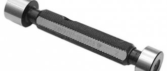
Plug gauges
They are a rod with cylindrical elements at both ends. One of them has the largest maximum hole size and is called a no-go plug (NOT), and the second is the smallest and is called a go-through plug (PR). The no-go plug is noticeably shorter than the go-through plug, thanks to which the worker or inspector quickly and correctly determines the suitability of the parts.
Smooth plug gauges are made in composite parts, with steel or plastic handles in which inserts with conical shanks or cylindrical attachments are attached. To check holes in the range from 2 to 50 mm, conical shanks are made, and for holes in the range of 30-100 mm, cylindrical nozzles are made. If the insert is only on one side of the handle, then such plug gauges are called one-sided.
Gauge gauges
They are used to control shaft diameters; they are available in single-sided and double-sided designs. just as in the case of plugs, the PR bracket must pass, and the bracket must NOT pass along the shaft. Otherwise, the shaft is considered unusable, and the defect will be correctable only if it is necessary to remove excess metal to achieve the desired result.
When using brackets, under no circumstances should they be forced onto the shaft, as the bracket may “open up” and increase the distance between the measuring surfaces due to the compliance caused by its design. To prevent this, you should put the bracket on a horizontal shaft only under the influence of its own weight. At the same time, the shaft is also rotated, which at the same time allows one to check deviations from the round profile in the cross section.
The clamps are available for checking only one size (they are called rigid) and adjustable, which allow you to control a certain range of shaft diameters. Adjustable parts are made of hard alloys, which significantly increases their service life.
Probe gauges
These are sets of steel plates with a thickness of 0.02 to 1 mm and a length of 100 or 200 mm. They are used to control the size of the gap between surfaces when assembling various mechanisms. In this case, one or more probes in a set are inserted into the gap to select the desired value.
When using probes, it is important to follow certain rules:
- when measuring, the probe should move smoothly with little effort, and not fall freely;
- For smooth movement of the plates, it is recommended to lightly lubricate them;
- Do not apply much force to the probe so as not to damage it;
- The size of the gap is determined by summing the thicknesses of all the probes from the set that are completely included in the gap.
Cone gauges
Serve for testing conical surfaces, such as instrument cones. Using a ring gauge, the suitability of the outer surfaces is checked, and with a stopper, the suitability of the internal surfaces is checked. A part is considered suitable if its end is located in the area between the marks or between the planes of the ledge. This distance is equal to the tolerance.
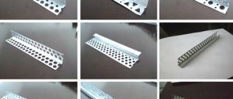
Gauges for checking the location of surfaces
There can be a variety of designs . With their help they control:
- coaxiality of two or more holes, as well as shaft journals;
- distances between the axes of the holes;
- parallelism, perpendicularity or amount of inclination of surfaces or axes;
- distance between the hole axis and the plane;
- the depth of various grooves and ledges.
The measuring elements of this type of gauge are arranged in such a way as to reproduce the configuration of the surfaces of the mating parts.
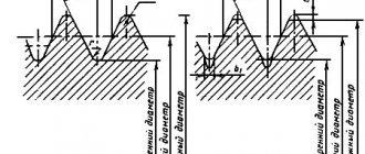
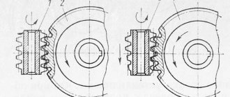
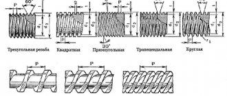
Gauges for inspection of cylindrical threads
Used for a comprehensive check of the average diameter, profile angle, as well as the largest internal diameter of the external thread or the smallest external diameter of the internal thread. Using these devices, metric, inch, trapezoidal, thrust and round threads with a diameter of 1 to 600 mm are checked.
The control set consists of working pass (PR) and non-pass (NOT) gauges , as well as control ones, which are used to check the working ring gauges and plugs.
Go-through gauges must screw freely into the controlled thread, while non-go-through gauges must not screw into it. It is allowed to screw on non-go gauges up to 2 turns, and the number of turns is determined when unscrewing the gauge and the controlled product. If the thread of the part being tested is short (less than 3 turns), then screwing on a non-go gauge is not allowed.
The PR thread gauge has a length of about 80% of the make-up length, that is, the length of contact between the bolt and nut threads, measured along their axis.
For a non-passable one, the length is at least 3 turns.
Requirements for manufacturing and operation
The following conditions apply to all calibers, regardless of their purpose and type:
- High accuracy of positioning of working surfaces. Tolerances for the manufacture of calibers are significantly smaller than the permissible deviations of controlled products.
- Rigidity that does not allow deformation during measurement. Mainly concerns large-sized staples.
- Good wear resistance, reduces the cost of manufacturing and checking calibers. Measuring elements are made from alloy steel grades X, ShKh15, tool steels U10A, U12A, as well as hard alloys.
- Corrosion resistance through the use of special coatings.
- Mandatory marking of calibers indicating the nominal size and its maximum deviations.
Since calibers are an expensive and important instrument, it is recommended to strictly follow certain rules when working with them:
- Do not apply force or shock to the caliber under any circumstances;
- tested surfaces must be clean, dry and free of burrs;
- when checking a part, it is prohibited to rotate it;
- It is impossible to control hot or warm products, since this changes their dimensions and the calibers wear out faster;
- strictly adhere to the deadlines for control checks.
During storage, the working surfaces of the calibers should not come into contact with metal objects.
How to use the tool
The rules for using such tools depend on their purpose. It is allowed to be used only in compliance with certain rules and the established accuracy class indicated in the marking. The use of plug gauges to control the accuracy of manufactured holes is allowed only with the help of a tool close to the parameters of the hole itself. The main condition for measurement accuracy is the free passage of the gauge insert through the hole being measured. Correct use of such devices requires compliance with the following rules:
- the passage side should enter the hole only under the influence of its own weight;
- It is prohibited to use additional methods of external influence (additional pressure, blows);
- Before checking, it is necessary to clean the parts from dirt and mechanical processing residues;
- Any type of lubricant that could affect the penetration of the gauge into the hole should be removed;
- the check must be carried out without rotating the meter relative to the part being examined;
- a prerequisite is compliance with the temperature regime (parts should be checked only at natural temperature);
- The frequency of inspections of the instrument itself and the rules for recording the results in established documents must be observed;
- each caliber must be stored in accordance with the established storage procedure (they should not come into contact with other metal parts or be exposed to external influences).
The thread template should be used in compliance with the characteristics of the thread (external or internal).
To control external threads, it is enough to apply the tool itself to the threads and determine the degree of coincidence. The internal thread is checked by screwing the head into a finished threaded hole. The process should be easy without effort or distortion.
To check the surface of the tapered shaft, use a suitable smooth tool. Quality is determined by the alignment of the surface of the part and the surface of the gauge. Comparison of the internal cone is made by immersing the nozzle into the prepared hole.
Calibers carry out operational control of product parameters of a large number of parts. This does not require special knowledge and skills in using complex metrological instruments. The operation is carried out promptly. You can compare several parameters at the same time.