Defects in threaded connections
When inspecting threaded surfaces, the following defects in threaded connections can be identified:
- Torn cuts. This defect occurs when the diameters of the hole and rod differ from the nominal diameter. The cause may also be insufficient sharpness of the cutting tool. To prevent this problem, it is necessary to carefully check the values of all diameters and replace a dull tool with a sharpened one.
- Dumb cut. This defect appears if the nominal diameter is smaller than the hole diameter, but larger than the rod diameter. As a result, when cutting, the profile becomes incomplete. To avoid such a defect, you need to take accurate diameter measurements before cutting.
- Thread taper. The cause of this defect is the incorrect size of the cutting object, the teeth of which cut off excess metal. The only way to solve this problem is to correlate the established dimensions of the part and the cutting device.
- Tight cutting. If the dimensions of the part and the roughness of the tool thread are not observed, the cutting process is difficult to carry out. This defect is prevented by correctly measuring the workpiece parameters and determining the correct dimensions of the cutting tools.
To control thread defects, gauges are used. They are divided into the following varieties:
- Location caliber. This type of gauge is created according to the average permissible dimensions of the part being controlled. The check occurs by inserting the location gauge into the workpiece. If the cutting is done properly, then the entry should be made with more or less density smoothly and smoothly.
- Calibers with limits. This type of gauge is manufactured in accordance with the maximum dimensions of the original workpiece. It is divided into 2 sides. One of them corresponds to the maximum part size, the other to the minimum. One side must not fit into the hole being measured so that the master can determine the true dimensions of the part.
- Control calibers. This type of gauge is designed to check hole parameters directly during the working process.
- Receiving gauges. These gauges are specialized tools that are the primary working devices for technical control department (QC) employees who carry out their activities at inspection points.
ACCEPTANCE
3.1. To check the compliance of wires and rollers with the requirements of this standard, state tests, acceptance inspection, periodic tests and reliability tests are carried out.
3.2. The procedure for conducting state tests is in accordance with GOST 8.383* and GOST 8.001*. _______________ * PR 50.2.009-94 is in force on the territory of the Russian Federation.
3.3. When carrying out acceptance inspection, each wire or roller should be checked for compliance with the requirements of paragraphs 1.8 and 2.9.
Check according to paragraph 1.8 (regarding the error in the shape of the working surface of wires with a nominal diameter of up to 0.346 mm), 2.2; 2.6; 2.8; 2.10; 2.12 (regarding demagnetization), 5.1; 5.4 should be carried out selectively according to GOST 18242 and GOST 18321.
Sampling plan:
control level - II;
type of control - normal;
type of control plan - single-stage;
sample size from the batch - according to GOST 18242*;
the method of selection from the batch is “blind” according to GOST 18321;
acceptance level of defects - =0.65. _______________ * GOST R 50779.71-99 is in force on the territory of the Russian Federation.
The batch meets the established requirements if the number of defects in the sample is less than or equal to the acceptance number and does not meet the established requirements if it is equal to or greater than the rejection number for a given inspection plan.
3.4. Periodic tests are carried out at least once every three years for compliance with the requirements of paragraph 1.1; 1.7; 1.8; 2.2; 2.4; 2.5; 2.6; 2.8; 2.9; 2.10; 2.12.
For testing, at least 10 sets of wires and rollers are selected from those that have passed acceptance control, including at least two nominal diameters of the 0th and 1st accuracy classes.
If during periodic testing it is discovered that the wires or rollers do not comply with at least one requirement of this standard, then twice the number of wires or rollers of a given size are tested.
The results of repeated tests are final.
3.5. Compliance with the requirement of clause 2.13 is confirmed by the results of an analysis of the controlled operation of at least 10 sets of wires or rollers, which can be combined with periodic tests.
Thread control devices
To calculate the characteristics of metric threads using a comprehensive control method, gauges in the form of rings and staples are used. Measurements are carried out in accordance with GOST 17763. Internal threading is controlled by plug gauges. Control of cutting with a profile angle of 55° is carried out using a micrometer with special inserts. The measuring device is equipped with 5 sets of inserts, the size of which is determined by the thread pitch. There are 2 main types of inserts:
- prismatic: installed in place of the micrometer heel;
- conical: placed in the hole of the micrometer screw.
Download GOST 17763-72
To control the angle of the thread profile, QD workers use devices with built-in indicators: microscopes and projectors. They can be equipped with sliding inserts and ball-shaped tips. The design of devices with indicators consists of a stop bar, a holder and indicators. The main advantage of indicator devices is their versatility. With their help, you can carry out measuring work both during boring and when turning a part. They provide high measurement accuracy in a short period of time.
There are additional devices with indicators for monitoring the taper of the part. They are created according to the international API standard and define the size of threaded connections in the range from 1.5 to 24 inches. The design of these devices is represented by removable measuring tips. They transmit the measurement results to a separate indicator, which displays the received data on the screen. A craftsman who uses indicator instruments to determine the taper of a part will not need approximate templates for control. This feature is due to the fact that instrument tips always try to provide the highest readings for the indicator at a minimum distance of 1 inch.
When inspecting threads, employees of factories and factories use calipers and weights to measure linear units of measurement. They help determine the size of the cutter used to remove the required amount of chips from the workpiece. These measuring instruments save time when machining medium to high precision holes.
What are metric and inch threads
Before you figure out how to determine the thread pitch using a thread gauge, you need to find out how a metric thread differs from an inch thread and vice versa? Threads according to the system of measures are divided into two main types:
- Metric - used on the following types of fasteners: bolts, screws, nuts, studs and others. The metric type of cutting originated in the Soviet Union and is actively used today
- Inch is the American cutting standard that home craftsmen encounter when working with plumbing products. However, inch cutting is found not only on plumbing fixtures, but also on fasteners
Let's look in more detail at the question of how metric threads differ from inch threads, and where they are used most often.
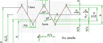
A distinctive feature of metric threads (GOST 24705-91) in the corresponding profile shape, which looks like an equilateral triangle.
The angle between the vertices of this triangle is 60 degrees, as mentioned above. The vertices or peaks are blunt in shape, that is, the projections for mating with the screw or nut are cut off. The unit of measurement used to indicate the screw diameter and thread pitch is millimeters. Threads of this type can have coarse and fine pitch, which depends on the scope of application of the relevant parts. Parts with small pitches are used primarily for adjustment, as well as in devices subject to dynamic loads. To designate large threads, markings in the form of the letter M and the corresponding number are used, for example, 20. This means that a metric thread with a diameter of 20 mm is cut on the workpiece. Small threads on the workpiece have a similar designation, only a digital value is added. This value indicates the thread pitch, for example 1.5 mm. The photo below shows a diagram of a metric thread device.
In addition to metric, inch threads are often used (GOST 6111-52).
Beginners who do not know about the existence of these two types of cutting face some difficulties. To understand what these difficulties are, consider the design features of inch threads. In profile it has a similar shape as the metric one, but its main difference is the modified angle between the vertices. This angle is 55 degrees, which distinguishes it in design from metric cutting. The unit of measurement used to indicate the dimensions of inch threads is inches. There are 25.4 mm in 1 inch, and two strokes are used to indicate inches. Inch thread can also be large or small, and is characterized by the number of threads per inch. It will not work to screw a nut with a metric thread onto a part with an inch thread, and vice versa.
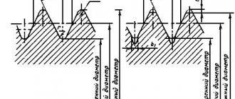
Inch and metric threads are external and internal, and their main technical parameters are:
- Pitch is the distance between the two tops of the turns
- Depth - distance from top to bottom
- Profile angle is the distance in degrees between the side parts of the profile in the plane of the axis
- Outer diameter - the size of the workpiece in the area where the thread is present, measured at the tops of the turns
- The inner diameter is the distance that corresponds to the size of the cylinder with the coils present
Thread parameters
When you know the difference between metric threads and inch threads, you can begin to consider the question of how to learn how to use a thread gauge. Although this device has a simple design, not everyone is able to correctly make the appropriate measurements (in addition, many do not know that there is a special tool). The effectiveness of the connection depends on the correctness of the actions performed.
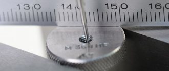
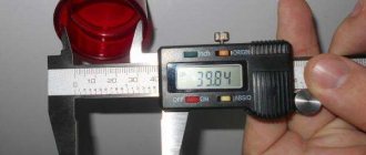
Thread pitch measurement
To control such characteristics as thread pitch, standard rulers with millimeter and inch graduations, as well as thread gauges, are used. The results of pitch calculations using a ruler are inaccurate and are made by measuring a certain number of turns. The main task of measurement is to find the number of turns per unit thread pitch. In the conventional case, when there are 5 turns per 1 inch, the pitch is 1/5 inch. For convenience, the results obtained in inches are converted to millimeters. During the process of measuring turns using a ruler, a person must take into account the following features:
- To achieve maximum accuracy, you need to measure not individual sections, but the entire part of the part profile.
- Before the measurement procedure, it is necessary to count the whole number of turns.
- The thread pitch is determined after measuring the depth and main characteristics of the threaded connections.
As a result of the measurements, the average step value is found. The calculation error depends on the correct cutting of the part.
The thread gauge is able to provide the most accurate pitch measurements for tapered pipe threads because it can handle the tightest distances.
Its design includes plates made of iron alloys. Each plate is equipped with cutouts equivalent to the cutting profile and its pitch. To determine the pitch size, the thread gauge is applied to the part being measured. The thread gauge plate only produces accurate control when it is parallel to the threading axis. It is important that the plate and the thread hole match in size.
Stroke and step
Important threaded elements are:
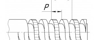
- Step. This parameter represents the distance at which the profile points of the same name are located in a direction parallel to the axis. This is a section that separates points of the same name on two adjacent turns. Denoted by the letter "P". Based on the diameter of the product, connections with steps are used:
- large (main);
small.
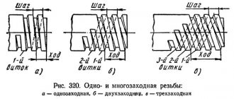
- Thread stroke. This definition should be understood as a segment with a length equal to the distance in the direction parallel to the thread axis between two identical points on adjacent turns of the same run. Designated Ph. It is equal to:
- single-start - step, i.e. Ph=P;
- multi-pass – the product of the number of passes by the step length, i.e. Ph=nP.
For products with a diameter of less than 68 mm, threads with large and small pitches are used. Threads for products with a diameter of more than 68 mm are cut only in small steps.
The pitch is indicated on the marking, and it can also be determined from parametric tables. Large steps, they are basic, are not indicated on the labeling. Also the step is determined by:
- measurements with thread gauges (thread gauges);
- comparison of threads of various parts with each other;
- screwing into the internal thread of an external thread, and there should be no resistance to screwing;
- measuring the stroke using a caliper and dividing the resulting value by the number of passes.
To measure pitch, it is recommended to use a bolt rather than a nut, because it is possible to control the measurement process visually. The purpose of determining the pitch is the correct choice of cutting tool or drill for the thread hole.
Measuring the average diameter of a thread
The average cutting diameter is controlled with a micrometer. The main components of this tool are replaceable tips that are inserted into the screw hole. This gauge provides the most accurate thread measurements available.
If only average values of thread diameter are needed for work, then you can use a special device - calipers. Its device is represented by ball tips, the dimensions of which must correspond to the type and pitch of threaded connections. The tips of the calipers are placed along the thread gauge, giving the average diameter size. After this, you need to do similar actions with the sides of the part. Threaded clamps are used to check the results obtained. Diameter accuracy is assessed by comparing the resulting thread with the original template.
If it is necessary to control the average diameter of a short length, consisting of a maximum of 2 turns, then the craftsmen use a method that involves 2 wires. This method of measuring threads differs in that wires, the diameter of which is a tabular unit, are placed on the opposite protrusions and valleys of the thread. The distance between the ends of the wires shows the average diameter of the part. For each accuracy class, separate wires are produced, created in accordance with GOST 2475-88. When determining the final numbers, it is necessary to take into account possible errors, because 2 wires do not allow you to obtain the most accurate values.
Download GOST 2475-88
This thread parameter can also be measured using a microscope. The device is applied to the sides of the workpiece profile. The microscope eyepieces are aimed at the profile image on each side to determine its size. The resulting values are added and divided by the number of sides. The resulting arithmetic mean is the actual value of the average diameter of the threaded connections.
For production work, it is often necessary to additionally monitor the average shaft diameter. They contain bearings, couplings, sides and gears, with the help of which the part rotates. Its diameter is calculated during the torsion process. The final value is found by the formula d=(T/0.2[t])1/3. The final result may be affected by extraneous factors (hole size and side height).
TYPES, MAIN DIMENSIONS AND TOLERANCES
1. TYPES, MAIN DIMENSIONS AND TOLERANCES
1.1. Wires and rollers must be made of the following types:
I - smooth wires (Fig. 1);
II - stepped wires (Fig. 2);
III - rollers (Fig. 3).
| mm | mm | ||||||
| Damn.1 | Damn.2 | Damn.3 | |||||
Note. - the working surface of type I wire should be located in the middle of the wire along the length
1.2. The nominal diameters of wires and rollers for measuring the average diameter of an external thread, depending on the pitch, are given in Tables 1 and 2.
Table 1
| Dimensions in mm | |||||||
| Step | Thread type and profile angle | ||||||
| metric =60° | trapezoidal =30° | persistent =33°, =30°, =3° | |||||
| 0,075 | 0,045 | 0,054 | — | — | — | — | — |
| 0,08 | 0,048 | 0,058 | 0,040 | ||||
| 0,09 | 0,052 | 0,062 | 0,045 | ||||
| 0,1 | 0,058 | 0,070 | 0,051 | ||||
| 0,125 | 0,073 | 0,088 | 0,063 | ||||
| 0,15 | 0,088 | 0,106 | 0,076 | ||||
| 0,175 | 0,101 | 0,121 | 0,089 | ||||
| 0,2 | 0,115 | 0,138 | 0,102 | ||||
| 0,225 | 0,130 | 0,156 | 0,114 | ||||
| 0,25 | 0,144 | 0,172 | 0,127 | ||||
| 0,3 | 0,173 | 0,208 | 0,152 | ||||
| 0,35 | 0,202 | 0,242 | 0,177 | ||||
| 0,4 | 0,231 | 0,277 | 0,203 | ||||
| 0,45 | 0,260 | 0,312 | 0,228 | ||||
| 0,5 | 0,289 | 0,347 | 0,253 | ||||
| 0,6 | 0,346 | 0,415 | 0,304 | ||||
| 0,7 | 0,404 | 0,485 | 0,354 | ||||
| 0,75 | 0,433 | 0,520 | 0,379 | ||||
| 0,8 | 0,462 | 0,554 | 0,405 | ||||
| 1,0 | 0,577 | 0,692 | 0,506 | ||||
| 1,25 | 0,722 | 0,866 | 0,632 | ||||
| 1,5 | 0,866 | 1,039 | 0,758 | 0,776 | 0,866 | ||
| 1,75 | 1,010 | 1,212 | 0,885 | — | — | ||
| 2,0 | 1,155 | 1,386 | 1,011 | 1,035 | 1,155 | 1,086 | 1,173 |
| 2,5 | 1,443 | 1,732 | 1,264 | — | — | — | — |
| 3,0 | 1,732 | 2,078 | 1,516 | 1,553 | 1,732 | 1,629 | 1,759 |
| 3,5 | 2,021 | 2,425 | 1,769 | — | — | — | — |
| 4,0 | 2,309 | 2,771 | 2,021 | 2,071 | 2,278 | 2,173 | 2,347 |
| 4,5 | 2,598 | 3,118 | 2,274 | — | — | — | — |
| 5,0 | 2,887 | 3,464 | 2,527 | 2,588 | 2,847 | 2,716 | 2,933 |
| 5,5 | 3,175 | 3,810 | 2,779 | — | — | — | — |
| 6,0 | 3,464 | 4,157 | 3,032 | 3,106 | 3,417 | 3,259 | 3,520 |
| 7,0 | — | — | — | 3,623 | 3,985 | — | — |
| 8,0 | 4,141 | 4,555 | 4,345 | 4,693 | |||
| 9,0 | 4,659 | 5,125 | — | — | |||
| 10 | 5,176 | 5,694 | 5,431 | 5,865 | |||
| 12 | 6,212 | 6,833 | 6,518 | 7,039 | |||
| 14 | 7,247 | 7,972 | 7,603 | 8,211 | |||
| 16 | 8,282 | 9,110 | 8,690 | 9,385 | |||
| 18 | 9,317 | 10,249 | 9,776 | 10,558 | |||
| 20 | 10,353 | 11,388 | 10,950 | 11,826 | |||
| 22 | 11,388 | 12,527 | 11,948 | 12,904 | |||
| 24 | 12,423 | 13,665 | 13,133 | 14,184 | |||
| 28 | 14,493 | 15,942 | 15,207 | 16,424 | |||
| 32 | 16,565 | 18,222 | 17,362 | 18,760 | |||
| 36 | 18,634 | 20,497 | 20,152 | 21,764 | |||
| 40 | 20,706 | 22,777 | 21,863 | 23,612 | |||
| 44 | 22,774 | 24,951 | 23,896 | 25,808 | |||
| 48 | 24,845 | 27,329 | 26,069 | 28,154 | |||
Note. For trapezoidal and thrust threads, values are not given, since wires and rollers of these sizes will be located below the outer diameter of the controlled profile.
table 2
| Dimensions in mm | ||||||
| Thread type and profile angle | ||||||
| Number of steps per length 24.5 mm | unified (inch) =60° | pipe cylindrical and conical =55°, inch =55° | ||||
| 80 | 0,183 | 0,220 | 0,161 | — | — | — |
| 72 | 0,204 | 0,245 | 0,179 | |||
| 64 | 0,229 | 0,275 | 0,201 | |||
| 56 | 0,262 | 0,314 | 0,230 | |||
| 48 | 0,306 | 0,367 | 0,268 | |||
| 44 | 0,333 | 0,400 | 0,292 | |||
| 40 | 0,367 | 0,440 | 0,321 | |||
| 36 | 0,407 | 0,488 | 0,357 | |||
| 32 | 0,458 | 0,550 | 0,402 | |||
| 28 | 0,524 | 0,629 | 0,459 | 0,511 | 0,613 | 0,459 |
| 27 | 0,543 | 0,652 | 0,475 | — | — | — |
| 24 | 0,611 | 0,733 | 0,535 | 0,596 | 0,716 | 0,535 |
| 20 | 0,733 | 0,880 | 0,642 | 0,716 | 0,859 | 0,643 |
| 19 | — | — | — | 0,754 | 0,905 | 0,676 |
| 18 | 0,815 | 0,978 | 0,713 | 0,795 | 0,954 | 0,714 |
| 16 | 0,917 | 1,100 | 0,803 | 0,895 | 1,074 | 0,803 |
| 14 | 1,048 | 1,258 | 0,917 | 1,023 | 1,228 | 0,918 |
| 13 | 1,128 | 1,354 | 0,988 | — | — | — |
| 12 | 1,222 | 1,466 | 1,070 | 1,193 | 1,432 | 1,071 |
| 1,275 | 1,530 | 1,116 | — | — | — | |
| 11 | 1,333 | 1,600 | 1,167 | 1,302 | 1,562 | 1,168 |
| 10 | 1,467 | 1,760 | 1,284 | 1,432 | 1,718 | 1,285 |
| 9 | 1,629 | 1,955 | 1,426 | 1,591 | 1,909 | 1,427 |
| 8 | 1,833 | 2,200 | 1,605 | 1,790 | 2,148 | 1,606 |
| 7 | 2,095 | 2,514 | 1,834 | 2,045 | 2,454 | 1,835 |
| 6 | 2,444 | 2,933 | 2,139 | 2,387 | 2,846 | 2,141 |
| 5 | 2,933 | 3,520 | 2,567 | 2,864 | 3,437 | 2,569 |
| 3,259 | 3,911 | 2,852 | 3,182 | 3,818 | 2,854 | |
| 4 | 3,666 | 4,399 | 3,209 | 3,579 | 4,295 | 3,211 |
| — | — | — | 4,091 | 4,909 | 3,670 | |
| 4,406 | 5,287 | 3,952 | ||||
| 3 | 4,773 | 5,728 | 4,281 | |||
| — | — | — | 4,980 | 5,976 | 4,467 | |
| 5,207 | 6,248 | 4,672 | ||||
| 5,454 | 6,545 | 4,893 | ||||
| 5,727 | 6,872 | 5,137 | ||||
For each specific type of thread and pitch, the values given in Tables 1-3 are preferable for use.
Table 3
mm
| 1,00 | 2,00 | 3,25 | 5,00 | 7,00 | 12,00 | 20,00 | 35,00 |
| 1,25 | 2,25 | 3,50 | 5,25 | 8,00 | 14,00 | 22,00 | |
| 1,40 | 2,50 | 4,00 | 5,50 | 9,00 | 15,00 | 25,00 | |
| 1,50 | 2,75 | 4,25 | 6,00 | 10,00 | 16,00 | 28,00 | |
| 1,75 | 3,00 | 4,50 | 6,50 | 11,00 | 18,00 | 30,00 | |
It is allowed to use wires and rollers of other diameters within the limits of ; , choosing them from among the preferred ones.
1.3. Recommendations for the use of wires and rollers are given in Appendix 1.
1.4. A summary table of the nominal diameters of wires and rollers for measuring the average diameter of an external thread is given in Appendix 2.
1.5. Formulas for calculating the diameters of wires and rollers for measuring the average diameter of an external thread are given in Appendix 3.
1.6. The nominal diameters of wires and rollers for measuring the parameters of spline joints with an involute profile are given in Table 3.
1.7. The lengths of the wires and rollers and the working surface must correspond to those indicated in Table 4.
Table 4
mm
| Diameter range | ||
| Until 3 | From 30 to 40 | 14 |
| » 4 | 35 » 45 | 14 |
| » 4 » 5 | 40 » 50 | 14 |
| » 5 | 50 » 55 | 40 |
Note. The length of the wires intended for use with the device for installation on the device is not specified.
1.8. The numerical values of the maximum deviations of wires and rollers, depending on accuracy classes 0 and 1, should not exceed those indicated in Table 5.
Table 5
| Diameter range, mm | Maximum deviation, µm | |
| Accuracy class 0 | Accuracy class 1 | |
| Up to 4,980 | ±0,3 | ±0,5 |
| From 5.176 to 8.690 | ±0,4 | |
| From 10.353 to 26.069 | ±0,5 | ±1,0 |
| From 28,000 to 35,000 | — | |
Deviations in the shape of the working surface of the wire and roller (any deviation from roundness or longitudinal section profile) must be within the diameter tolerance.
Measuring the outer diameter of a thread
Control of the outer diameter of the thread is carried out using micrometric tools, the basis of which are microscrews. The calculation occurs in accordance with the following algorithm:
- Microscrews are applied to the thread profile. To adjust the position of the tool, it is necessary to make several rotations of the micrometer.
- Record the cutting profile size for one side. The value is calculated based on the division value on the microscrew scale.
- Apply a micrometer to the opposite end of the profile and calculate its size.
- Find the outer diameter of the cut by subtracting the value of the second calculation from the result of the initial calculation.
Measuring the internal diameter of a thread
The internal diameter of the cutting is controlled by a measuring device with pointed legs - calipers. To organize computational work, you need to install the tool on a template part using a threaded gauge, and then make a comparison with the original internal diameter of the threaded connections. The caliper must be at an angle relative to the axis being measured.
Also, measuring internal threads can be carried out with instruments for cylindrical threads. This is because the inside diameter has a smooth surface, which is ideal for the shape of the tips used in these instruments. Verification of the obtained measurements is done using plug gauges.
Measuring threads using the three-wire method
The three-wire method is mainly used to control the average thread diameter. The diameter values are determined by placing wires of the same diameter on the cavities of the threaded connections. The size of the resulting structure is measured with a micrometer. The final result of the calculations can be greatly influenced by the profile error. To eliminate this error, it is necessary to place the wires on the profile so that they are connected at the level where the width of the depressions is equivalent to the width of the protrusions. The wires must lie as follows: 1 wire is placed on the depression on the left side, and the other 2 wires are placed on the depressions on the opposite side. It is important that during measurements the part was not deformed and the wires were not bent
In addition, the scope of application of the three-wire method is to control the diameter of trapezoidal threads. Only in this case, the part is checked using three special rollers.