Purpose
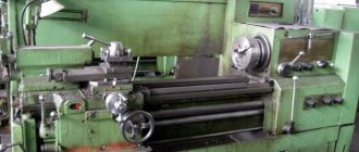
CNC lathes are modern versions of standard machine analogues, equipped with a number of additional functions, one of which is the presence of a CNC system. Such devices are designed for processing metal workpieces by turning, but can also be used to work with other materials. Thanks to this, lathes have become universal devices used in various fields. The main area of application is in factories and at home.
Using CNC machines:
- External and internal turning of parts is carried out;
- cone-shaped elements or having other complex shapes are manufactured;
- longitudinal processing of the workpiece is performed;
- roughing and finishing processing is carried out;
- the length of the parts is adjustable;
- grooves, recesses, holes are machined;
- Inch and metric threads are cut.
This machine is able to cope with a task of almost any level of complexity. Therefore, the scope of application of CNC machines for turning work is in enterprises engaged in the serial production of parts. Also, the use of lathes is noted in frequent production in small businesses.
Classification
These machines come in three types:
- contour;
- positional;
- adaptive.
The first type includes devices operating along a given trajectory. Such units require operator control. The second type includes machines capable of performing point-to-point processing on a device. The third type combines the capabilities of a contouring and positioning machine.
Domestic machines go on sale with a certain marking, with the help of which you can determine the capabilities of the equipment. The marking includes a letter and a number. The most common models are marked:
- F1 – the working mechanism performs processing according to predetermined coordinates;
- F2 – the working mechanism carries out point processing;
- F3 – sets the trajectory along which turning is performed on CNC machines under the control of the operator;
- F4 – combined processing, combining the capabilities of contour and positioning machines.
Also, lathes with program control differ:
- location of the spindle axis;
- location of guides;
- design features;
- type of processing performed.
Devices with numerical control are divided into accuracy levels, each of which corresponds to a specific marking:
- N – normal;
- P – increased;
- B – high;
- A – extra high;
- C – highly precise devices (master machines only).
The marking is selected depending on where the machine tool is planned to be used. If the letter “C” is present in the marking of a domestic machine, this indicates the presence of additional capabilities of the device.
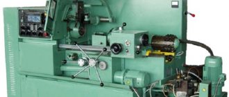
Design
Unlike older analogues, modern machines with numerical control have a higher rigidity index and allow complex processing of parts to be completed in a shorter period. These advantages are due to design features:
- absence of gaps between subordinate elements;
- high level of strength of load-bearing elements, unit components and other components;
- minimum length of kinetic chains and number of mechanical gears;
- presence of feedback alarms;
- increased resistance to vibration loads arising during processing of parts;
- the presence of special systems designed to reduce the risk of thermal deformation.
Turning on machines is ensured thanks to guides. These components are subject to wear, but are resistant to friction. The structural elements are interconnected and operate in the same mode. This condition is associated with the high precision of products.
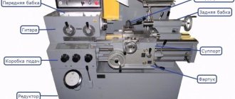
The basic design of a lathe consists of:
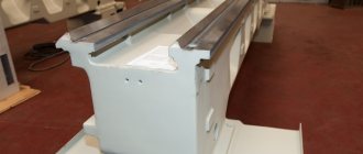
- beds;
- spindle or headstock;
- calipers;
- feed boxes;
- electrical part;
- turret heads.
The bed is the basis of the equipment on which the remaining components of the machine tool are placed. The headstock consists of two main elements of the unit: the gearbox and the spindle. The support includes a lower and upper carriage - elements that fix the working mechanism. The caliper receives movement through the feed box. The device operates using an electric motor. This component is similar for different models of lathes, and may differ only in power. Tool turrets are used to automatically change tools.
When working with large workpieces, machines can be used whose design includes special stands. They are used to fix the part at the desired height.
There are also turning centers on sale that add the functions of a milling machine to a lathe.
Coordinate systems for CNC lathes
When preparing control programs for CNC machines, the most labor-intensive stage is the calculation of the tool path, which very much depends on the correct choice and mutual coordination of the coordinate systems of the part, machine and tool.
In the coordinate system of CNC lathes, the initial and current positions of the working parts of the machine and their maximum movements are determined. The choice of machine coordinate system must comply with ISO recommendations. The standard coordinate system is a right-handed rectangular XYZ Cartesian coordinate system (Figure 2).
Rice. 2. Designation of tool movements and location of coordinate axes in CNC machines
In addition to the three main Cartesian coordinates, the relative position of the tool and the workpiece is characterized by possible additional rotations and movements.
So, the fourth coordinate can be associated with the rotation of the table, the fifth with the rotation of the spindle, the sixth with additional movement of the spindle head, etc.
The axis of the working spindle is taken as the initial Z axis. If there is a counter spindle, the Z1 axis is distinguished for the main and Z2 axis for the counter spindle, the X axis is always horizontal (Fig. 3). The positive direction of movement of the working body is considered to be the one in which the tool and the workpiece move away from each other. It must be remembered that this coordinate system differs from the coordinate system adopted for calculating cutting forces.
In addition to the main axes X and Z, of which there can be several, and axes C1 and C2, there are also axes B and Y, which control the machines. Average positioning accuracy 0.005. . .0.008 mm. Travel speeds along the X, Z (Y) axes from 15 to 40 m/min; Along the C axis, positioning is performed at a speed of 100 min-1. Indexing of the main and sub-spindle is ensured at 0.0001°. Acceleration when moving reaches 10 m/s2.
Rice. 3. Position of the axes on a CNC lathe with a counter spindle and two turrets
When processing a part on a CNC machine, three position coordinate systems can be distinguished. The first is the XMZ machine coordinate system, which has its origin at point M - the zero of the machine. In this system, the positions of the base points of individual machine components are determined.
The second is the workpiece coordinate system. It is intended to specify the coordinates of the reference points of the machined surfaces, as well as the coordinates of the tool path reference points. The right rectangular, cylindrical and spherical coordinate systems are used as the workpiece coordinate system. The coordinates of a point in it are the distances x, y, z from the point to three mutually perpendicular coordinate planes. In a cylindrical coordinate system, a point is specified by the radius vector p, the central angle φ, which determines the position of the projection of the point on the main plane, and the applicate z. In the spherical system, the coordinates of the point are the radius vector r, longitude φ and polar angle θ.
And the third system is the tool coordinate system, in which the position of the center P of the tool relative to the base point F (K, T) of the machine element carrying the tool is determined. The tool coordinate system is designed to specify the position of its setting point relative to the holder or the center of rotation of the tool head. The Xi, Zi axes are parallel to the axes of the machine coordinate system and are directed in the same direction.
If a machine has several working bodies carrying a tool, different coordinate systems are used to specify their movements. In contrast to the axes X, Y, Z (primary), the axes parallel to them, located further from the spindle, are called secondary and are designated, respectively, U, V, W. The axes of the third working body are designated by the letters P, Q, R.
The presence of a connection between the coordinate systems of the machine, the part and the tool allows you to maintain the specified accuracy of machining the part when it is reinstalled, and when preparing the control program, set the trajectory of the tool in the coordinate system of the part
Principle of operation
Operation of CNC lathes depends on the characteristics of the device used. The choice of machine depends on:
- permissible thickness of the workpiece being processed;
- the maximum distance that can be set between the central parts of the headstocks;
- permissible diameter of the part installed above the support.
The tailstock is used to install a cutter or other working tool. The movement of the headstock is carried out along the trajectory of the rails located on the frame. The length of movement is equal to the dimensions of the workpiece. The working tool moves along the workpiece, the movement of which depends on the carriage. The caliper is responsible for ensuring that its position does not get lost during turning.
The single holder is used for simple machining. More complex tasks are accomplished with heads that can accommodate multiple cutters. The largest number of incisors is four.
The use of parts using such a device should be preferred when working with complex shapes.
The electric motor uses a belt drive. It is capable of providing high performance. The disadvantage of this transmission is that the belt stretches. To maintain performance at a high level, the belt is periodically tightened.
Designs of the main components of CNC machines
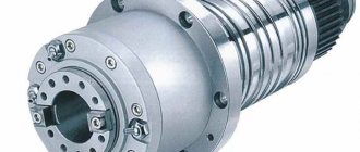
In the main movement drives of lathes, the headstock is usually spindle-type. High power and rotation speeds, high load on spindle bearings led to the need for intensive cooling, which is provided mainly by finning the headstock or passing coolant (Fig. 5).
Rice. 5. Ribbing system for spindle units of machine tools from HAAS (USA)
Variable DC and AC motors are commonly used as drive motors in CNC machines. The latter are simpler in design and more reliable due to the absence of brush units (especially in the area of high rotation speeds required for the main movement). The control range of a motor with constant power (Rд)р is limited to the value 3. . . 5 (in the latest engine models 6... 8), which, as a rule, requires the use of mechanical devices (gearboxes) with a number of speed stages from two to four in the main motion drive.
Preference is given to the motor-spindle option, which provides more power, but still everywhere the movement from the electric motor to the spindle is transmitted using a V-ribbed or toothed belt. The spindle assembly itself has become replaceable. Due to the advent of better tool materials for machines with a chuck with a diameter of 250 mm, the spindle rotation speed is now over 10,000 min-1 with a power reaching up to 43 kW.
In lathes, instead of gear kinematic chains, backlash-free ball screws with high-torque adjustable electric motors are used, which ensures precise movement of the supports. In this case, not only are the friction forces significantly reduced (the static friction coefficient for rolling guides is 20 times less than for sliding guides) and intermittency of movement caused by the sticking effect during sliding is eliminated, but also the wear of the interface is reduced.
A significant share of manufactured machines (about a third) are CNC lathes with a vertical spindle or two spindles. It has become common practice that the tailstock is replaced with a counter spindle with characteristics equal to or similar to those of the main spindle. The time for transferring a workpiece from one spindle to another is about 10 s and is achieved either by “running over” the counter spindle, or using a manipulator (INTEGREX 200 machine -IIIST from MAZAK (Japan)).
On lathes, the tool is installed in the turret in 12, less often 10 (8) positions. An option is available for a turret head for 24 tools (Fig. 6).
The cross-sectional size of the cutter installed in the turret ranges from 20 to 32 mm, and the diameter of the axial tool ranges from 32 to 50 mm. As a rule, all positions of the turret head (12, 24) or most of them are driven. The time for changing adjacent tools is from 0.15 to 1 s, although it is not uncommon to change a tool in 4 s. More than a quarter of all CNC machines have two, three or even four turrets that can work simultaneously (Fig. 7).
Rice. 6. Turret head for 24 tools, of which 18 are driven with a speed of 9000 min-1 and a power of 6 kW
Rice. 7. TD42-Triplex series turning center (without guard) with two spindles and three turrets
As a rule, machine tools are equipped with measurement systems for both the workpiece and part, as well as the tool, which eliminates the need for precise measurements before processing begins.
The position of the bed guides in space is traditionally inclined. Most modern medium-sized CNC machines have an original layout that allows them to increase their rigidity, improve the protection of guides and screw gears, ensure free drainage of chips and remove them from the working area, use loading devices of any type, provide free access to tools and accessories, and increase safety work