Methods and instruments for monitoring thread parameters
Thread inspection is a set of procedures for measuring important cutting characteristics. To effectively measure thread parameters, it is necessary to correctly determine the methods and means of control. When monitoring the basic cutting parameters, three-wire methods are most often used; the means of control are measuring devices with indicators and micrometers. There are 2 main ways to control threads:
- Differentiation method: each element is measured separately.
- Comprehensive testing method: all parameters are checked together using scale-free instruments.
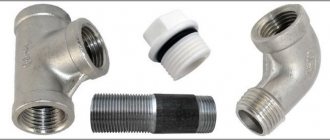
To control pipe and tapered threads, gauges are most often used to measure the dimensions, shape and relative position of the surface of the part.
Measuring the internal diameter of a thread
The internal diameter of the cutting is controlled by a measuring device with pointed legs - calipers. To organize computational work, you need to install the tool on a template part using a threaded gauge, and then make a comparison with the original internal diameter of the threaded connections. The caliper must be at an angle relative to the axis being measured.
Also, measuring internal threads can be carried out with instruments for cylindrical threads. This is because the inside diameter has a smooth surface, which is ideal for the shape of the tips used in these instruments. Verification of the obtained measurements is done using plug gauges.
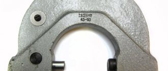
Design and scope of application of thread gauges
The main purpose of the thread gauge is to monitor the condition of the thread and its compliance with GOST requirements. Therefore, it is often used in metalworking production, mechanical engineering, and during repair and assembly operations of machines and equipment. Almost all assembly shops and repair shops have sets of thread gauges for checking the profiles of rectangular, thrust and trapezoidal threads.
The thread gauge is a set of templates of manufactured steel plates with a thickness of about 1 mm. At one end of the plate there are cutouts corresponding to the caliber of the threads being measured - pitch and profile. These toothed plates are often called combs. On metric combs the thread pitch is indicated, on inch combs the number of threads per inch is indicated.
Using a thread gauge you can accurately determine:
- Thread pitch.
- Number of threads per unit distance.
- Thread wear condition.
- Compliance of the thread with existing GOST standards.
- Cleaning calibers from all types of contaminants
- Repair of calibers without disturbing the geometry of the calibers
- Application of protective coatings with packaging for proper transportation
- Calibration of gauges
- Repair of measuring instruments
- Calibration of measuring instruments
- Measuring geometric dimensions of finished products and workpieces of varying complexity
Caliber (control device) is a technical device designed to carry out control that is not based on measurements of product characteristics.
Through use and based on the results of using the caliber, a decision is made on whether the product meets or does not meet the established requirements.
There are the following main types of gauges: plugs, rings, staples.
Types of calibers are divided into types, depending on the design:
- smooth cylindrical plugs for checking holes;
- brackets for shaft control;
- smooth conical rings and plugs for preliminary control when cutting threaded connections;
- threaded cylindrical rings and plugs for monitoring cylindrical threaded connections;
- threaded conical rings and plugs for monitoring conical threaded connections.
Calibration is a set of operations performed in order to determine the actual values of metrological characteristics.
Smooth cylindrical gauges (rings, plugs).
Calibration of smooth cylindrical gauges is carried out in accordance with MI 1927-88 “Recommendation. Smooth gauges for cylindrical shafts and holes. Control technique".
The precision horizontal length gauge “Labconcept 500”, error ±(1.4+L/80) microns, manufactured by “TRIMOS”, Switzerland, is used as a standard.
Measured parameters of smooth cylindrical rings:
- inner diameter.
Measured parameters of smooth cylindrical plugs:
- outside diameter.
Calibers for shaft control - staples.
Staples are used to control shaft diameters. The precision horizontal length gauge “Labconcept 500”, error ±(1.4+L/80) microns, manufactured by “TRIMOS”, Switzerland, is used as a standard.
Measured parameters:
- inner diameter.
Smooth conical gauges GNK, OTTG, OTTM and others (rings, plugs).
Calibration of threaded cylindrical gauges is carried out in accordance with MI 1904-88 “Recommendation. Gauge for conical connections. Control technique".
The precision horizontal length gauge “Labconcept 500”, error ±(1.4+L/80) microns, manufactured by “TRIMOS”, Switzerland, is used as a standard.
Measured parameters of smooth conical rings and plugs:
- diameter in the measuring plane;
- taper deviation along the length of the caliber.
Threaded cylindrical gauges M, Tr, G, UNF, UNC and others (rings, rings).
Calibration of threaded cylindrical gauges is carried out in accordance with MI 1904-88 “Recommendation. Threaded cylindrical gauges. Control technique".
The precision horizontal length gauge “Labconcept 500”, error ±(1.4+L/80) microns, manufactured by “TRIMOS”, Switzerland, is used as a standard.
Measured parameters of threaded cylindrical rings:
- inner diameter;
- average diameter.
Measured parameters of threaded cylindrical plugs:
- outside diameter;
- average diameter.
Threaded conical gauges R, K, Z, NKT, OTTM, BATRESS and others (rings, plugs).
Calibration of threaded conical gauges is carried out in accordance with MI 1812-87 “Methodological instructions. Threaded conical gauges. Control technique".
The precision horizontal length gauge “Labconcept 500”, error ±(1.4+L/80) microns, manufactured by “TRIMOS”, Switzerland, is used as a standard.
To calibrate threaded conical gauges, the measurement method on a sine ruler GOST 4046-80 “Sine rulers” can also be used. Technical conditions".
Measured parameters of threaded conical rings and plugs:
- paired tension of a threaded pair;
- average diameter in the main plane;
- outer diameter in the main plane;
- deviation of taper along the average diameter.
Measurements of geometric quantities of finished products and workpieces.
Measuring thread profile parameters.
To measure the parameters of the internal thread profile using an impression, the composite impression material COMPAR-S is used. The impression material KOMPAR-S is intended for obtaining high-precision impressions with subsequent control of the profile using an instrumental microscope UIM-23. The error in measuring the geometric parameters of the casts does not exceed 8 µm for linear values and 10' for angular values.
Measuring tools and methods for measuring threads
To determine the main thread sizes, mechanical engineering and instrument making enterprises use various measuring instruments - universal and special.
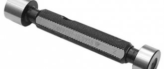
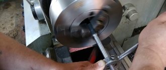
Special - micrometers, calibers, microscopes and a number of others. In Fig. Figure 4.1 shows a gauge for checking threads in a hole. On one side of the caliber there is a threaded plug - “pass”, and on the other - “not pass”. The part is considered suitable if a pass-through caliber plug is screwed into the hole and a non-go-through plug is not screwed in.
In the Engineering Graphics course, when studying threads in laboratory work, a universal measuring instrument is used - a caliper type ShTs-11 (Fig. 4.2), with a measuring scale division (vernier) of 0.1 mm or 0.05 mm and a caliper with a depth gauge and division value – 0.1 mm.
Universal meters include calipers of various designs. Measuring instruments student
Fig. 4.1 The gauge for measuring threads is studied in the course “Metrology, standard-
M10x1.5 in the hole ation and technical measurements" or in
other courses where issues of interchangeability and technology of manufacturing and quality control of products are the main ones in the training of a specialist.
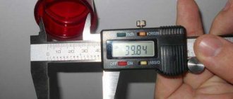
In Fig. Figure 4.3 shows a caliper with a depth gauge and the process of measuring the internal diameter D2 of a thread in a hole.
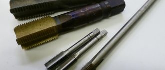
The thread pitch is determined with a special tool - a thread gauge, Fig. 4.4a or special templates, Fig. 4.4 b.
The thread gauge is used for both external threads and threads in holes.
In cases where for some reason there is no thread gauge, an approximate method is used - the impression method, Fig. 4.5 (right) or measure the length of several steps directly with a ruler. The essence of the method
Rice. 4.2 Vernier calipers type ШЦ - 11
Rice. 4.3 Diameter measurement Fig. 4.4 Measuring thread pitch with a thread gauge
internal thread metric
is clear from Fig. 4.5. Having determined in one way or another the length of the sum of the steps of several threaded threads, divide this length by the number of steps. Such methods are called indirect, since the result is obtained not by direct measurement, but after calculations according to certain formulas or rules. As a result, we obtain approximately the value
Rice. 4.5 Measuring the pitch using a ruler directly on the thread (left) and on the print (right)
step. The resulting number is compared with GOST tables and the actual step size is established.
Based on the measured diameters and pitch, the remaining geometric parameters of the threads are determined by comparing the obtained data with GOST tables.
Thread inspection
| Heading | Production and technology |
| View | abstract |
| Language | Russian |
| Date added | 28.10.2013 |
| file size | 200.9 K |
- see the text of the work
- You can download the work here
- complete information about the job
- the whole list of similar works
Send your good work in the knowledge base is simple. Use the form below
Students, graduate students, young scientists who use the knowledge base in their studies and work will be very grateful to you.
Posted on https://www.allbest.ru/
Posted on https://www.allbest.ru/
ABSTRACT
Thread inspection
Connections are important elements of mechanical engineering structures. Experience in operating vehicles has shown that a large number of failures in their operation are associated with unsatisfactory quality of connections. Therefore, the main criterion for the performance of connections (as well as the corresponding calculations) is strength.
Based on their detachability, all types of connections can be divided into
To detachable connections
, which can be disassembled without damaging their constituent parts, belong to:
To permanent connections,
which cannot be disassembled without damaging their constituent parts belong to:
Threaded connections
Thread measuring instruments. Thread measuring wires.
Active control devices.
One of the most progressive control methods is active. Its most rational use is in conditions of mass and large-scale production. Active control devices for a certain dimensional measurement allow you to automatically change the course of the technological process and ensure the specified processing accuracy.
Active control devices can be turned on at the end of the processing cycle and, based on the measurement results, issue a command for sub-adjustment of the cutting tool (they are called sub-adjusters) or check the dimensions of the product directly during processing in order to regulate the amount of movement, cutting modes and other parameters of the technological process. Active control devices that regulate the parameters of technological processes are used in computer-controlled machines.
Scanners and flaw detectors
Reducing the cost and simplifying the quality check of bolts is inextricably linked with the cost of this fastener, affecting the final price of the product in which it is used. This is why inspection devices designed for mass inspection of bolts are so necessary.
As such devices, flaw detectors suitable for parameters, configured to work with bolts, or special scanners are used.
One of the devices of this format is BOLTSCAN, created specifically for checking the quality of bolts. This device provides prompt and accurate quality control of threaded fasteners according to several main parameters. These parameters allow you to verify the reliability of the two most vulnerable places of any bolt - the thread and the transition point from the rod to the head.
The productivity and efficiency of this device are such that it is not only possible, but also profitable to use in assessing the quality of bolts during total piece-by-piece inspection. The device operates on the basis of the eddy current method; rotation of the bolt allows for circular, that is, exhaustive and complete control of the most important places of any bolt. Here are the main bolt parameters that can be checked on such a device:
- bolt length - more than 100 mm
- control zone -100 mm
- bolt diameter - from 5 to 20 mm.
The compact desktop configuration of this scanner allows it to be used in any production environment or inspection room.
- Cleaning calibers from all types of contaminants
- Repair of calibers without disturbing the geometry of the calibers
- Application of protective coatings with packaging for proper transportation
- Calibration of gauges
- Repair of measuring instruments
- Calibration of measuring instruments
- Measuring geometric dimensions of finished products and workpieces of varying complexity
Caliber (control device) is a technical device designed to carry out control that is not based on measurements of product characteristics.
Through use and based on the results of using the caliber, a decision is made on whether the product meets or does not meet the established requirements.
There are the following main types of gauges: plugs, rings, staples.
Types of calibers are divided into types, depending on the design:
- smooth cylindrical plugs for checking holes;
- brackets for shaft control;
- smooth conical rings and plugs for preliminary control when cutting threaded connections;
- threaded cylindrical rings and plugs for monitoring cylindrical threaded connections;
- threaded conical rings and plugs for monitoring conical threaded connections.
Calibration is a set of operations performed in order to determine the actual values of metrological characteristics.
Smooth cylindrical gauges (rings, plugs).
Calibration of smooth cylindrical gauges is carried out in accordance with MI 1927-88 “Recommendation. Smooth gauges for cylindrical shafts and holes. Control technique".
The precision horizontal length gauge “Labconcept 500”, error ±(1.4+L/80) microns, manufactured by “TRIMOS”, Switzerland, is used as a standard.
Measured parameters of smooth cylindrical rings:
- inner diameter.
Measured parameters of smooth cylindrical plugs:
- outside diameter.
Calibers for shaft control - staples.
Staples are used to control shaft diameters. The precision horizontal length gauge “Labconcept 500”, error ±(1.4+L/80) microns, manufactured by “TRIMOS”, Switzerland, is used as a standard.
Measuring the average diameter of a thread
The average cutting diameter is controlled with a micrometer. The main components of this tool are replaceable tips that are inserted into the screw hole. This gauge provides the most accurate thread measurements available.
If only average values of thread diameter are needed for work, then you can use a special device - calipers. Its device is represented by ball tips, the dimensions of which must correspond to the type and pitch of threaded connections. The tips of the calipers are placed along the thread gauge, giving the average diameter size. After this, you need to do similar actions with the sides of the part. Threaded clamps are used to check the results obtained. Diameter accuracy is assessed by comparing the resulting thread with the original template.
If it is necessary to control the average diameter of a short length, consisting of a maximum of 2 turns, then the craftsmen use a method that involves 2 wires. This method of measuring threads differs in that wires, the diameter of which is a tabular unit, are placed on the opposite protrusions and valleys of the thread. The distance between the ends of the wires shows the average diameter of the part. For each accuracy class, separate wires are produced, created in accordance with GOST 2475-88. When determining the final numbers, it is necessary to take into account possible errors, because 2 wires do not allow you to obtain the most accurate values.
Download GOST 2475-88
This thread parameter can also be measured using a microscope. The device is applied to the sides of the workpiece profile. The microscope eyepieces are aimed at the profile image on each side to determine its size. The resulting values are added and divided by the number of sides. The resulting arithmetic mean is the actual value of the average diameter of the threaded connections.
For production work, it is often necessary to additionally monitor the average shaft diameter. They contain bearings, couplings, sides and gears, with the help of which the part rotates. Its diameter is calculated during the torsion process. The final value is found by the formula d=(T/0.2[t]) 1/3. The final result may be affected by extraneous factors (hole size and side height).
Application of calibers
Insert plugs are the main type of threaded plugs and have a tapered shank. They are manufactured with diameters from 1 to 50 mm. The sealing of threaded connections with an outer diameter from 50 to 100 mm is made in the form of nozzles, fixed at the ends of the plastic handle with screws. External threads are checked using threaded rings made with a diameter of 1 to 100 mm. Pass-through rings are cut along the entire width of the ring. Their outer surface is rolled. Impassable rings have a shortened thread (only two or three turns with a shortened thread are left). They create a distinctive groove in the middle of the outer knurled cylindrical surface of the ring.
Trapezoidal
Threaded connections of this type most often include screw-nut type connections. Trapezoidal threads are made in accordance with GOST 9481-81. Its shape is an isosceles trapezoid. The angle of inclination of the edges is 30°. For the threads of fasteners used in worm gears, an inclination angle of 40° is provided.
The trapezoidal thread profile allows for increased connection strength. Due to this, it is used to connect parts of mechanisms that operate under the influence of dynamic loads, for example, in running nuts that secure valve stems, etc.
Measuring thread pitch without a thread gauge
Parts with external thread
Often the need to determine the thread pitch arises sporadically, at one time. And, of course, in such a situation there is no thread gauge at hand, and it makes no sense to buy one for one-time measurements. It will be useful to learn how to measure the thread pitch with a ruler or caliper. These measuring tools make it quite easy to determine the desired parameter.
The easiest way is to measure the threads of a bolt or other externally threaded part. When measuring a metric thread, it is recommended that you first attach the ruler to the threaded part and try to align the millimeter divisions of its scale with the tops of the ridges of the threaded profile. If they coincide, then the step is 1 mm. Otherwise, you will have to carry out slightly more complex measurements.
To determine the thread pitch, you need to count the number of turns on a section of a rod of a certain length, for example, 10 mm or 20 mm. To obtain a more accurate result, it is recommended to take measurements on a 20 mm area. The required length is measured by applying a ruler to the bolt shaft, or using a caliper. It would be more accurate to measure the bolt thread pitch with a caliper. In the measured area, count the number of turns. After this, the length of the section must be divided by the resulting number of turns minus one turn. As a result, we obtain the value of the thread pitch.
When determining the pitch of an inch cutting, it is necessary to measure the length of the rod equal to one inch (25.4 mm). For accurate measurements, it is better to use a ruler or caliper with an inch scale. The number of turns in this area will be the thread pitch. If the length of the threaded section is less than one inch, then you need to determine the number of turns in a section of half an inch (12.7 mm), and then multiply the result by 2.
Internally threaded parts
There are two ways to measure the thread of a nut or other internally threaded part without a thread gauge. The first method involves selecting an exactly suitable counter bolt and then measuring its thread pitch. If you can’t find the counter bolt, then you need to use a strip of paper (this is method No. 2).
It should be pressed against the thread so that an imprint of the profile remains on the paper. You can improve the visibility of marks by tracing the edges with a marker. After this, on paper you need to mark the distance between the extreme marks with a ruler and count the number of turns. Then the resulting distance is divided by the number of turns minus one turn. Instead of measuring paper using this method, you can use a pencil, match or other soft wood product of a suitable size, which is pressed against the thread.