Tool design
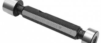
This measuring tool is made from a solid metal bar. At both ends there are cylindrical elements of a given diameter. Therefore, they are divided into the following classes:
- measuring;
- threaded;
- smooth (one-sided or two-sided);
- checkpoints;
- limit.
Each device structurally consists of the following elements:
- handles (with applied corrugation according to GOST 14748-69);
- inserts;
- dowels;
- fixing screw.
Download GOST 14748-69
For example, a threaded plug gauge as an insert is used to check metric threads. They are divided into two categories: for checking threads from 1 to 68 mm and from 68 to 200 mm. Requirements for them are given in special standards. All screw plugs are available in full or short thread designs. Each of the plugs has its own specific application.
Based on established standards, smooth limit plugs are divided into the following designs:
- double-sided with cylindrical inserts;
- with conical inserts;
- with cylindrical nozzles;
- complete and incomplete;
- single-sided sheets;
- full and incomplete washers.
The smooth double-sided plug gauge has corresponding inserts at both ends of the handle. One plug is called a through plug and is designated by the abbreviation “PR”. The second plug is not passable and is marked “NOT”. The dimensions of smooth plug gauges are determined by their purpose and are given in the standard for such instruments. The main parameters are the outer diameter, the size of the head (insert) and the processing accuracy class. To carry out inspections of holes with a diameter ranging from five to twenty millimeters, a cone-shaped nozzle is made for the plug. For holes of larger diameter, such a nozzle is made cylindrical.
Smooth straight-through plugs are produced based on existing standard sizes. Intermediate plugs have the closest size according to GOST. Limit plug gauges consist of the same elements as pass-through gauges. Each size of an individual plug part is indicated on the drawing. It serves to determine the exact size of the structure and the order of its application.
Machine tools
Calibers are manufactured in the following types:
- Plug thread gauges PR and NOT.
- Threaded ring gauges PR and NOT.
- Control plug gauges for threaded rings KPR-PR, KNE-PR, KPR-NE, KNE-NE.
- Control plug gauges for checking the wear of threaded rings KI, KI-NE.
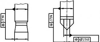
- Plugs PR and control plugs KPR-PR, KNE-PR, KNE-NE, KI-NE have a full profile (drawing 1).
- PR rings have a full profile (Figure 2).
- The HE plugs and control plugs KPR-NE, KI have a shortened profile (Drawing 3).
- The rings do NOT have a shortened profile (Drawing 4).
WE SUPPLY FULL PROFILE GAUGES ONLY VERSION “b” with vertices cut along a chord passing through the tangent points of the circular arc of the rounded thread profile according to GOST 6357-81 by the value u/2 and with a groove width b1
Calibers are manufactured in the range from G 1/16″ to G 6″ accuracy classes A and B
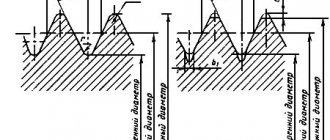
Initial data for calculating the as-built dimensions of threads and gauges for checking threads:
H=0.960491P, h=0.640327P
d2=D2=d-0.640327P, d1=D1=d-1.280654P
| Diameter | Pitch, mm | Step, thread | b1, max mm | u, mm | r, max | Td, mkm | Td2, Td2, mkm | TD1, mkm | es | EI | |||||||||||||
| A | B | ||||||||||||||||||||||
| From 1/16 to 1/8 | 0,907 | 28 | 0,2 | 0,134 | 0,125 | 214 | 107 | 214 | 282 | 0 | 0 | ||||||||||||
| From ¼ to 3/8 | 1,337 | 19 | 0,3 | 0,198 | 0,184 | 250 | 125 | 250 | 445 | 0 | 0 | ||||||||||||
| from ½ to 7/8 | 1,814 | 14 | 0,4 | 0,268 | 0,249 | 284 | 142 | 284 | 541 | 0 | 0 | ||||||||||||
| From 1 to 2 | 2,309 | 11 | 0,5 | 0,341 | 0,317 | 360 | 180 | 360 | 640 | 0 | 0 | ||||||||||||
| 2-1/4 to 6 | 2,309 | 11 | 0,5 | 0,341 | 0,317 | 434 | 217 | 434 | 640 | 0 | 0 | ||||||||||||
| Tolerances of thread gauges and values that determine the position of the tolerance fields and the wear limit of thread gauges in microns | |||||||||||||||||||||||
| Td2, TD2 thread | Tr | Tpl | Tcp | m | Zr | Zpl | Wgo | Wng | |||||||||||||||
| ring | cork | ring | cork | ||||||||||||||||||||
| Over 80 to 125 | 15 | 10 | 9 | 17 | 2 | 8 | 18 | 14 | 13 | 10 | |||||||||||||
| …125…200 | 20 | 12 | 10 | 20 | 9 | 13 | 23 | 19 | 17 | 13 | |||||||||||||
| …200…315 | 25 | 15 | 13 | 24 | 13 | 18 | 28 | 23 | 21 | 17 | |||||||||||||
| …315…500 | 33 | 20 | 17 | 30 | 20 | 24 | 33 | 27 | 28 | 19 | |||||||||||||
| Calculation of thread gauges | |||||||||||||||||||||||
| Caliber name | D | D2 | D1 max | ||||||||||||||||||||
| max | min | max | min | wear | |||||||||||||||||||
| Plug PR | Du | Du-Tpl | D2+Zpl+Tpl/2 | D2+Zpl-Tpl/2 | D2+Zpl-Wgo | D1 | |||||||||||||||||
| Cork NOT | D2+TD2+2F1+1.5Tpl | D2+TD2+2F1-Tpl/2 | D2+TD2+Tpl | D2+TD2 | D2+TD2+Tpl/2-Wng | D1-TD2 | |||||||||||||||||
| Caliber name | dmin | d2 | d1 | ||||||||||||||||||||
| min | max | min | max | ||||||||||||||||||||
| Ring PR | D | d2-Zr-Tr/2 | d2-Zr+Tr/2 | d1+u | d1+u+Tr | ||||||||||||||||||
| Ring NOT | d+Tpl | d2-Td2-Tr | d2-Td2 | d2-Td2-2F1-1.5Tr | d2-Td2-2F1+Tr/2 | ||||||||||||||||||
| Caliber name | D | D2 | D1 max | ||||||||||||||||||||
| max | min | max | min | ||||||||||||||||||||
| Control plug CI | d2-Zr+Wgo+2F1+Tpl/2 | d2-Zr+Wgo+2F1-Tpl/2 | d2-Zr+Wgo+Tcp/2 | d2-Zr+Wgo-Tcp/2 | d1-Tpl | ||||||||||||||||||
| Control plug KPR-PR | du | du-Tpl | d2-Zr-m+Tcp/2 | d2-Zr-m-Tcp/2 | d1-Tpl | ||||||||||||||||||
| Control plug KPR-NE | d2-Zr+Tr/2+2F1+Tpl/2 | d2-Zr+Tr/2+2F1-Tpl/2 | d2-Zr+Tr/2+Tcp/2 | d2-Zr+Tr/2-Tcp/2 | d1-Tpl | ||||||||||||||||||
| Control plug KI-NE | d-Td2-Tr/2+Wng+Tpl | d-Td2-Tr/2+Wng-Tpl | d2-Td2-Tr/2+Wng+Tcp/2 | d2-Td2-Tr/2+Wng-Tcp/2 | D1 | ||||||||||||||||||
| Control plug KNE-PR | d+Tpl | d-Tpl | d2-Td2-Tr/2-m+Tcp/2 | d2-Td2-Tr/2-m-Tcp/2 | D1 | ||||||||||||||||||
| Control plug KNE-NE | d-Td2+Tpl | d-Td2-Tpl | d2-Td2+Tcp/2 | d2-Td2-Tcp/2 | D1 | ||||||||||||||||||
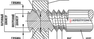
Purpose of the plug gauge
These scaleless measuring systems are used to check the accuracy of machining operations performed on various parts. Depending on the type of work (turning, milling, drilling), plugs are designed to control the following results:
- diameter of the drilled hole after all types of processing;
- establishing the accuracy class of surface treatment;
- geometric (linear) dimensions;
- angles of inclination of surfaces relative to given normals;
- compliance of the shape of the processed part with the specified parameters;
- correct relative position of surfaces;
- correct thread cutting (internal and external).
The absence of a direct indicator, scale or digital, in these measuring instruments requires the creation of a large number of such devices. This is due to the fact that each tool can only be used to monitor one parameter. The use of such measuring devices makes it possible to mechanize the inspection operation and reduce the time in the technological chain for this operation. Reducing the time required to monitor mandatory parameters can significantly increase labor productivity.
Therefore, the following types of products are currently used:
- smooth plug gauges;
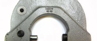
- staples;
- feelers (usually flat plates of a certain thickness for measuring the gap between parts, that is, checking its permitted value);
- conical (the nozzle has the shape of a cone at a given angle of inclination);
- for the relative position of surfaces;
- thread gauges (for checking cylindrical threads of various sizes).
Each of the listed types has its own purpose. The first type is intended for assessing the parameters of manufactured pipes. It is used to quickly check the quality of manufactured pipelines. Compliance with all necessary parameters established by the standard.
Threaded ones are intended only for checking the quality of the cut thread. They are made shortened or full (to increase control accuracy). With the help of shortened gauges, only part of the cut thread can be checked, which makes it difficult to obtain a complete picture of the quality of the manufactured part. To get a complete picture of accuracy and quality, threads are tested using full thread designs.
Full control of pipe products is carried out using threaded and smooth gauges.
How to use the tool
The rules for using such tools depend on their purpose. It is allowed to be used only in compliance with certain rules and the established accuracy class indicated in the marking. The use of plug gauges to control the accuracy of manufactured holes is allowed only with the help of a tool close to the parameters of the hole itself. The main condition for measurement accuracy is the free passage of the gauge insert through the hole being measured. Correct use of such devices requires compliance with the following rules:
- the passage side should enter the hole only under the influence of its own weight;
- It is prohibited to use additional methods of external influence (additional pressure, blows);
- Before checking, it is necessary to clean the parts from dirt and mechanical processing residues;
- Any type of lubricant that could affect the penetration of the gauge into the hole should be removed;
- the check must be carried out without rotating the meter relative to the part being examined;
- a prerequisite is compliance with the temperature regime (parts should be checked only at natural temperature);
- The frequency of inspections of the instrument itself and the rules for recording the results in established documents must be observed;
- each caliber must be stored in accordance with the established storage procedure (they should not come into contact with other metal parts or be exposed to external influences).
The thread template should be used in compliance with the characteristics of the thread (external or internal).
To control external threads, it is enough to apply the tool itself to the threads and determine the degree of coincidence. The internal thread is checked by screwing the head into a finished threaded hole. The process should be easy without effort or distortion.
To check the surface of the tapered shaft, use a suitable smooth tool. Quality is determined by the alignment of the surface of the part and the surface of the gauge. Comparison of the internal cone is made by immersing the nozzle into the prepared hole.
Calibers carry out operational control of product parameters of a large number of parts. This does not require special knowledge and skills in using complex metrological instruments. The operation is carried out promptly. You can compare several parameters at the same time.
Basic requirements for calibers
The main requirements for all calibers are set out in the technical documentation for their manufacture. These requirements are given in various GOSTs. They can be divided into the following categories:
- the correct choice of metal for the production of measuring attachments (high rigidity must be ensured, which prevents the slightest deformation during storage and operation);
- the arrangement of working elements (nozzles, plates, washers) must be carried out with a high degree of accuracy above the measured parameters;
- ensuring durability and wear resistance (this is ensured by the use of high-alloy tool steels and special alloys);
- high anti-corrosion resistance (use of special methods for processing calibers and resistant coatings);
- creation of a system of periodic metrological control (checks must be carried out in accordance with the established frequency and the results must be recorded in the appropriate journal);
- calibration of calibers must be carried out on equipment with a higher accuracy class than the caliber itself;
- strict adherence to the established labeling system with precise indication of all necessary parameters.
For example, the requirements for smooth plug gauges are set out in GOST 14810-69. This standard systematizes not only all requirements, but also defines all permissible parameters of these measuring instruments.
Download GOST 14810-69
Requirements for manufacturing and operation
The following conditions apply to all calibers, regardless of their purpose and type:
- High accuracy of positioning of working surfaces. Tolerances for the manufacture of calibers are significantly smaller than the permissible deviations of controlled products.
- Rigidity that does not allow deformation during measurement. Mainly concerns large-sized staples.
- Good wear resistance, reduces the cost of manufacturing and checking calibers. Measuring elements are made from alloy steel grades X, ShKh15, tool steels U10A, U12A, as well as hard alloys.
- Corrosion resistance through the use of special coatings.
- Mandatory marking of calibers indicating the nominal size and its maximum deviations.
Since calibers are an expensive and important instrument, it is recommended to strictly follow certain rules when working with them:
- Do not apply force or shock to the caliber under any circumstances;
- tested surfaces must be clean, dry and free of burrs;
- when checking a part, it is prohibited to rotate it;
- It is impossible to control hot or warm products, since this changes their dimensions and the calibers wear out faster;
- strictly adhere to the deadlines for control checks.
During storage, the working surfaces of the calibers should not come into contact with metal objects.