Information about the manufacturer of the surface grinding machine 3B722
The manufacturer of the 3B722 surface grinding machine is the Lipetsk Machine Tool Plant , founded in 1929.
In 1956, the tractor repair plant was reoriented to produce machine tools and renamed the Lipetsk Machine Tool Plant.
Machines model 3B722 B are typical representatives of the range of surface grinding machines with a rectangular table of medium size and allow processing flat surfaces of a wide variety of parts with micron precision. When using additional devices, these machines can also process shaped surfaces.
Machine tools produced by the Lipetsk Machine Tool Plant, LSZ
- 3B722
- surface grinding machine with a horizontal spindle 320 x 1000 - 3D722
- surface grinding machine with a horizontal spindle 320 x 1000 - 3L722V, 3L722A
- surface grinding machine with a horizontal spindle 320 x 1000 - 3L742VF10
- surface grinding machine with round table Ø 630 - 3P722
- surface grinding machine with a horizontal spindle 320 x 1000; 320 x 1250; 320 x 1600
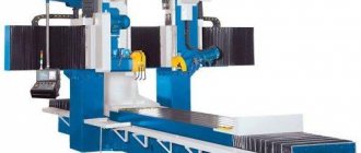
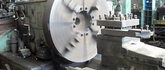
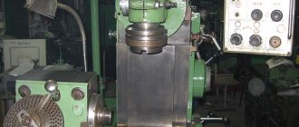
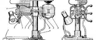
General view of the surface grinding machine 3B722
Photo of surface grinding machine 3B722
Photo of surface grinding machine 3B722
Photo of surface grinding machine 3B722
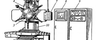
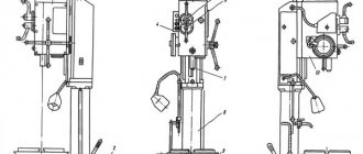
Location of components of the grinding machine 3B722
Location of components of the grinding machine 3B722
Specification of components of the grinding machine 3B722
- Housings - 3B722-80
- Carriage - 3B722-35
- Grinding head - 3B722-30
- Electrical equipment - 3B722-90a
- Table - 3B722-20
- Bed - 3B722-10
- Hydraulic feed box control panel - 3B722-41
- Grinding head hydraulic feed box - 3B722-54
- Table control panel - 3B722-40
- Hydraulic box for table reverse - NG-52
- Control panel - 3B722-91
- Electrical equipment pipeline - 3B722-92
- Pressure gauge valve - 3B722-48
- Hydrobox of a fairy tale of table guides - NG-60
- Reversible feed spool - 3B722-59a
- Spindle lubrication installation - 3B722-57a
- Bellows relay - NG-65V
- Accelerated movement mechanism - 3B722-37b
- Cooling - 3B722-75
- Electromagnetic plate for voltage 110, GOST 3860-56 EP-32G
- Magnetic separator – CM-3MA
- Accessories - 3B722-85
- Table cylinder - 3B722-50
- Pumping unit - 3B722-56
- Pipeline - 3B722-51
- Column - 3B722-15
- Grinding headstock reverse hydraulic box - 3B722-53
- Limit switch assembly - 3B722-46b
- Carriage gearbox - 3B722-26
- Grinding headstock cylinder - 3B722-52
- Column reducer - 3B722-27
- Screw drive support - 3B722-28
- Vertical feed mechanism - 3B722-36
- Feed mechanism plunger - 3B722-55
filter NG-62
Location of controls for grinding machine 3B722
Location of controls for grinding machine 3B722
Control panel for surface grinding machine 3B722
List of controls for the grinding machine 3B722
- Mobile table supports
- Table reverse lever from stops
- Reverse handle for hydraulic lateral movement of the grinding headstock
- Reverse stops for hydraulic movement of the grinding headstock
- Handle for turning on manual lateral movement of the grinding head
- Flywheel for manual lateral movement of the grinding headstock
- Emphasis
- Cooling valve
- Handwheel for manual vertical feed of grinding headstock
- Handle for changing the nature of the cross feed
- Throttle handle for regulating the amount of continuous cross feed
- Throttle handle for intermittent cross feed control
- Handle for setting the automatic vertical feed amount
- Handle for preparing the inclusion of accelerated vertical movement of the grinding headstock
- Hard Stop Installation Handle
- Button for disconnecting the dial from the flywheel
- Throttle handle to regulate table speed
- Manual table reverse handle
- Handle “Start”, “Stop”, “Unloading” of the table
- Light switch "On", "Off"
- Electromagnetic plate switch “On”, “Off”, “Demagnetized”
- Switch “Work with stove”, “Work without stove”
- Signal lamp "Stove on"
- Signal lamp “Presence of grease in spindle bearings”
- "General stop" button
- Hydraulics start button
- Hydraulic stop button
- Button for accelerated movement of the grinding head "Up"
- Button for accelerated movement of the grinding headstock “Down”
- Grinding wheel start button
- Grinding wheel stop button
- Cooling enable switch “On”, “Off”
- Automatic vertical feed switch “On”, “Disabled”
Design features of the machine
Appearance
The installation consists of a horizontal frame, on the surface of which there are guides, on which the workpiece is attached. During operation, a displacement is performed in the horizontal longitudinal direction. For processing large workpieces, slight shifts in the transverse direction are possible. The grinding wheel is fixed on the headstock. This aggregation unit can move in a vertical plane.
For normal operation of the equipment, the design includes 6 electric motors. The main drive of the headstock spindle is carried out by transmitting torque from a 10 kW power unit. For accelerated vertical displacement, a 1.1 kW electric motor is used. The remaining drive devices are designed to ensure the operation of the cooling systems and magnetic separator.
The 3B722 surface grinding machine has the following specific characteristics:
- methods of fixing parts. They can be flooded on the workbench by mechanical devices or by an electromagnetic plate;
- the grinding head moves along a stand with horizontal guides;
- the design contains rolling screw pairs;
- digital display system that controls the degree of displacement of the grinding wheel.
The presence of high-precision bearings ensures uniform processing of the material over the entire surface.
The design of the spindle unit allows you to select optimal operating modes - feeds and changing the speed of the work table. The sound power level should not exceed 99 dB.
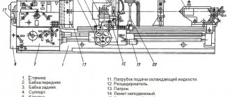
Kinematic diagram of surface grinding machine 3B722
Kinematic diagram of surface grinding machine 3B722
Vertical feed chain of the grinding headstock
Manual feed . The movement from flywheel 35 is transmitted through gears 23, 22, clutch 21, bevel gear pair 20, 19 to nut 18 connected to lead screw IX..
Since the nut is fixed against vertical movement, when it rotates, screw IX will move in the axial direction and move the carriage with the grinding headstock.
Automatic feeding . At the moment of reversing the grinding head, oil is supplied to one or another cavity of the cylinder of the feed mechanism 46 and moves the plunger rack 47. The latter, through the gear 48, rotates the crank 45, which, through the connecting rod 44, turns the lever 43 with the pawl 37 sitting on it at an angle of 40-50° .
The pawl turns the ratchet 25 connected to the flywheel 35. The movement is then transmitted along the chain described above to the screw.
The amount of automatic feed is adjusted by turning the cover 24, as a result of which the pawl 37 can turn the ratchet 25 along the entire path of its movement or part of it. The position of the cover 24 is changed from the handle 30 through gears 28, 27, 29, 26 and a gear sector cut on the cover 24.
To automatically stop the feed after removing the set allowance, a sector 31, 88 mounted on the limb 36 is used. At the same time, it enters the rolling zone of the pawl 37, which begins to slide along it without touching the teeth of the ratchet 25.
When working manually, a hard stop 38 is brought to the “hard stop” by the handle 39, against which the stop fixed on the dial 32 rests at the end of the stroke. The dial is connected to the flywheel 35 by means of a gear lock 33, which is activated by pressing the button 34.
Accelerated movement . An accelerated installation movement is prepared by turning the handle 41. In this case, using a helical groove on the shaft using a lever 49, gear 22 is disengaged from gear 23 and flywheel 35 is disconnected from the feed chain. At the same time, the cam 40 presses the limit switch 42, which unlocks the push-button station for starting the electric motor of the rapid movement mechanism.
When the electric motor is turned on, the movement from the electric motor shaft is transmitted by a silent chain through sprockets 52, 53. Gears 50, 51 to screw IX along the previously discussed chain.
In this case, the grinding head moves up or down.
Grinding headstock cross feed chain
Manual feed . From flywheel 12 through a worm gear (worm 5 - gear 4), rotation is transmitted to rack and pinion gear 2, which is meshed with rack I mounted on the grinding headstock.
To prevent the transmission from breaking when the grinding head is hydraulically moved from the cylinder, worm 5 is disengaged from gear 4 by turning handle II. In this case, the eccentric sleeve is blocked by cam 6 and lever 3, excluding the movement of the grinding head from the hydraulic cylinder when the worm is turned on.
Automatic feeding . When the grinding headstock moves transversely from the hydraulic cylinder, pin 17, mounted on the headstock body, slides along the spiral groove of shaft III, causing it to rotate. Next, through gears 16 and 15, a disk with adjustable stops 13 is driven into rotation. The disk with stops makes almost a full revolution at the maximum transverse passage of the grinding headstock, and the stops, acting on the reversible handle 14, rotate it together with the roller and the lever 9 sitting on it. The lever with one of its fingers acts (when reversing the grinding headstock) alternately on the limit switches 7 and 10, which give the command for vertical automatic feed, and with the other finger it switches lever 8, connected to the reversing spool of the grinding headstock reverse hydraulic box.
Handle 14 can also be used to manually reverse the grinding headstock.
Grinding head drive . The grinding wheel spindle receives rotational motion through a coupling from a flange-mounted electric motor with a power of 10 kW at 1460 rpm.
Specifications
According to the accepted classification, the 3B722 machine has an accuracy class of “P”. Thanks to the versatility of its design, it can process parts whose dimensions do not exceed 100*36*40 cm. Moreover, the distance from the spindle to the table surface can be from 19 to 63 cm.
The determining quality of the machine is the parameters of the spindle head. The maximum and minimum grinding depth, as well as the speed of this process, depend on its characteristics. The permissible dimensions of the grinding wheel range from 32.5 to 45 cm. In this case, the landing diameter is 20.3 cm. The spindle receives a maximum torque of 6.7 kgf*m.
In addition, you should take into account the following technical parameters that the spindle head of the 3B722 machine has:
- transverse displacement value – 40 cm;
- number of automatic feeds per table stroke – from 1 to 30;
- maximum vertical displacement – 44cm;
- characteristics of automatic vertical feeds – from 0.005 to 0.1 mm;
- vertical accelerated displacement speed – 0.45 m/min.
The machine can operate in automatic or manual feed mode. In the first case, it is necessary to use the automation system.
Technical parameters of the desktop:
- surface dimensions - 100*32 cm;
- dimensions of the fixed electromagnetic plate – 90*32 cm;
- longitudinal displacement value – from 30 to 105 cm;
- possibility of adjusting the speed of displacement of the work table - from 2 to 40 m/min.
In addition to these characteristics, it is worth noting the automatic stupor reverse. This function allows you to quickly respond to changes in the configuration of the workpiece.
The 3B722 surface grinding machine has large dimensions - 341 * 202 * 229 with a weight of 6950 kg without an installed part. This is due to the cast frame, which ensures the stability of the equipment during operation.
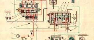
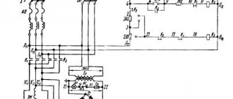
Electrical diagram of surface grinding machine 3B722
Electrical circuit of surface grinding machine 3B722
The voltage of the general AC supply network is 380 V.
Voltage of control circuits - 110 V, local lighting - 24 V, alarm - 5 V, DC control circuits - 110 V.
Description of the operation of the machine's electrical circuit
By turning the handle of the input batch switch PP1 to the “On” position, the power circuit of the machine is turned on (Fig. 18).
To prepare the circuit for operation, you must turn on the AI and A2 switch to the “On” position. Turn on the rotation of the grinding wheel.
Turning on the rotation of the grinding wheel is done by pressing the KU1 button again.
Button KU1 has two N.O. contacts 7-9 and 17 - II
The first contact turns on the short circuit contactor circuit, the second contact turns on the KI contactor, which is N.O. contact 17-II becomes self-powered and turns on electric motor D1.
Turning the electromagnetic cooker on and off
The machine is equipped with a magnetic plate to hold parts made of magnetic materials during the grinding process.
You can work without a magnetic plate. To select the type of work, switch P1 “Work with a stove” - “Without a stove” is installed on the remote control.
By turning the handle of this switch to the “Work with stove” position, the power circuit of the electromagnetic stove is prepared for switching on.
By turning the handle of switch P4 to the “On” position, contacts P1-P3 and P4-P2 are closed and voltage is supplied to the magnetic plate through the circuit P1-P3-P5-P4-P2
In this case, the electromagnetic relay P> is activated, the coil of which is connected in series with the magnetic plate. Relay P> with its N.O. contact 5-19 prepares the K2 contactor circuit for switching on, and contact 3-107 turns on the LS1 “Stove on” signal lamp. To remove products from the magnetic plate, you must move the handle of the drum switch to the “Demagnetized” position and release it.
Under the action of the spring, the handle will return to the zero position. In the zero position, contact P4-P6 closes, all other contacts are open, the plate, disconnected from the rectifier, is shunted by resistance R. Relay P> turns off, turning off the signal lamp LS1, and contact 5-19 opens.
In the “Demagnetized” position of the switch handle P4, its contacts P1-P4 and P2-P7 are closed and a reverse current of reduced strength flows in the coils of the electromagnetic plate due to the presence of part of the resistance R in the circuit. A short-term current pulse of reverse polarity is necessary to demagnetize the magnetic plate and partially ground parts.
Overhaul of a surface grinding machine
When operating the machine, not only the working tools wear out, but also the internal rotating components. This leads to a decrease in the quality of metalworking. Modernization and repair of 3L722V surface grinding machines is carried out in Lipetsk and the Moscow region.
When using a machine for up to 20 years, failure of its main components is unlikely. But every year the possibilities of new technologies of 3L722V equipment increase. In order for the machine to meet the latest requirements, it needs modernization and modification. Based on the fact that the basic scheme does not fundamentally change, and the basic parameters of the working surfaces are maintained, the modernization of the machine will not affect the appearance and dimensions of the equipment. For the master servicing the machine, the manufacturer’s manual for operation and maintenance of the 3L722V will remain relevant. Only some power characteristics of electrical equipment will change. What needs to be taken into account when replacing the characteristics of improved units in the instructions. A major overhaul of equipment manufactured half a century ago involves a complete update of the electrical systems. The general circuit will remain the same, but in operation the machine will become quieter and more powerful, which is justified by replacing the DC electric motor with a similar one operating on AC.
During the modernization process, when replacing the engine of a surface grinding machine, the gearbox and control system are changed. Manual settings are being replaced by CNC. Installing software control only makes sense on equipment that meets certain accuracy requirements. This quality is achieved by serviceable lead screws, bearings, gear reducers, smooth guides, and a well-functioning lubrication system.
Hydraulic equipment of surface grinding machine 3B722
Hydraulic equipment of surface grinding machine 3B722
Hydraulic diagram of surface grinding machines models 3B722 and 3B724
- filter
- filter
- pump
- pump
- pressure spool
- filter
- pressure spool
- pressure reducing valve
- throttle
- control distributor
- table movement hydraulic cylinder
- hydraulic cylinder for moving the grinding head
- grinding head control distributor
- throttle
- check valve
- lever arm
- grinding head control distributor
- hydraulic reverse gearbox for grinding headstock
- blocking distributor
- reverse lever
- check valve
- grinding head feed box
- dosing distributor
- throttle
- control distributor
- distributor controlling feed change
- throttle
- throttle
- check valve
- check valve
- throttle
- vertical feed cylinder
- table control panel
- throttle for adjusting the smoothness of table reverse
- distributor
- distributor
- table speed throttle
Description of the hydraulic drive of surface grinding machines 3B722 and 3B724
The hydraulic drive of the machine (Fig. 44) carries out:
- reciprocating table movement
- reciprocating movement of the grinding head
- vertical feed of the grinding head
- Lubricating table guides
- spindle bearing lubrication
The hydraulic drive of the machine has three main systems:
- high pressure (working system)
- low pressure (control system)
- Lubrication of grinding head bearings
Moving and reversing the table . Oil from the tank through filter 1 is supplied by pump 3 through pressure spool 7 to distributor 36.
When the distributor spool 36 is in the right position, oil enters the left cavity of the cylinder 11 attached to the table. The table moves to the left. The oil displaced from the right cavity of cylinder 11 is discharged into the tank through distributor 95 and throttle 37. Throttle 37 is used to regulate the table speed. When the table moves to the left, the stop with the help of lever 20 moves the distributor spool 25. In this case, oil from pump 4 through the pressure spool 5, distributor 25, check valve 29 will flow under the right end of the distributor spool 35 and move it to the extreme left position. Oil from under the left end of spool 35 is forced out through throttle 34 of distributor 25 into the tank. Throttle 34 is used to adjust the smoothness of table reverse.
As soon as the distributor spool 35 moves to the extreme left position, oil will begin to flow into the right cavity of the cylinder 11. The table will move to the right until the stop moves the distributor spool 25, after which the cycle will repeat.
Transverse feeds and reverse of the grinding headstock . The distributor spool 26 can occupy one of three positions (see Fig. 44): the far right corresponds to intermittent flow, the far left to continuous flow, and the middle to no flow. The distributor spool 13 can occupy one of two extreme positions: the right, corresponding to the movement of the grinding head by a hydraulic drive, and the left, corresponding to the movement of the grinding head manually.
Continuous feed of the grinding head . Oil from pump 4 through pressure spool 5, throttle 27, distributors 26 and 19 enters distributor 13. If distributor spool 13 is in the left position, then oil enters the rod cavity of cylinder 12 and the grinding head moves to the left. From the piston cavity of cylinder 12, oil is drained into the tank through distributors 13 and 17.
When lever 16 moves the distributor spool 17 to the right, oil from pump 4 through distributors 26, 19, 13, 17 and check valve 15 falls under the left end of the distributor spool 13 and moves it to the right position, directing the oil flow into the piston cavity of cylinder 12. Grinding headstock moves to the right. From the rod cavity of cylinder 12, oil is drained into the tank through distributors 13 and 17. Throttles 14 regulate the speed of movement of the distributor spool 13.
Intermittent transverse feed of the grinding head occurs with each table reverse, i.e., with each movement of the distributor spool 25. From pump 4, through distributor 25 and check valve 21, oil enters the right cavity of the metering distributor 3. From the left cavity of the metering distributor 23 through the throttle 24 distributor 25, the oil is drained into the tank. When the dispenser moves from one extreme position to the other, part of the oil from pump 3 through the pressure valve 7, throttle 28, distributor 26, dispenser 23 enters the distributor 19 and then flows in the same way as in the case of continuous supply.
Vertical intermittent feed of the grinding headstock . When reversing the cross feed of the grinding head, lever 16 turns on one of the electromagnets of the distributor 10 through the limit switches, moving its spool to one of the extreme positions. If the distributor spool 10 is in the left position, then the oil from the pump through the pressure spool 5 and check valve 30 enters the vertical feed cylinder 32 - the grinding headstock is fed vertically. From the left cavity of cylinder 32, oil through throttle 31 and distributor 10 is drained into the tank.
Vertical feed of the headstock in the opposite direction occurs in a similar way.
Possible malfunctions in the hydraulic drive of the surface grinding machine 3B722, ZB724
Before troubleshooting, you need to check the pressure in the hydraulic system. The pressure should be equal to: high (in the working system) 1.5-2 MPa, low (in the control system) - 0.6..0.8 MPa, in the lubrication system of the bed guides - 0.05 MPa, in the lubrication system of the grinding bearings headstock - 0.1 MPa.
Technical data and characteristics of the 3B722 machine
| Parameter name | 3B722 | 3D722 | 3L722V |
| Main settings | |||
| Accuracy class according to GOST 8-82 | P | P | B, A |
| The largest dimensions of processed products (length x width x height), mm | 1000 x 360 x 400 | 1000 x 320 x 400 | 1250 x 320 x 400 |
| The largest dimensions of processed products on an electromagnetic plate (length x width x height), mm | 900 x 320 x 280 | 1250 x 320 x 280 | |
| The smallest dimensions of processed products on an electromagnetic plate (length x width x height), mm | 50 x 40 x 5 | 50 x 40 x 3 | |
| Distance from the spindle axis to the table mirror, mm | 190..630 | 210..625 | 210..625 |
| The largest mass of products processed on the table, kg | 600 | 600 | |
| The largest mass of products processed on an electromagnetic plate, kg | 300 | 400 | |
| Machine work table | |||
| Dimensions of the working surface of the table (length x width), mm | 1000 x 320 | 1000 x 320 | 1000 x 320 |
| Surface dimensions of the electromagnetic plate (length x width), mm | 900 x 320 | 900 x 320 | |
| Longitudinal movement of the table from hydraulics (minimum/maximum, mm | 300..1050 | 300..1010 | |
| Speed of reciprocating table movement (stepless regulation), m/min | 2..40 | 3..45 | 3..35 |
| Grinding head | |||
| Grinding wheel dimensions (smallest and largest outer diameters), mm | 325…450 | ||
| Grinding wheel dimensions (internal diameter/height), mm | 203/ 63 | ||
| Grinding wheel dimensions according to GOST 2424-75 | PP450x80x203 | PP450x80x203 | |
| Grinding wheel revolutions per minute | 1460 | 1460 | 1460 |
| Maximum permissible torque on the spindle, kgf*m | 6,7 | ||
| Highest grinding speed, m/s | 34,4 | ||
| The end of the spindle of the grinding head according to GOST 2323-67, GOST 2323-76 (design/taper/largest diameter) | 1/ 1:5/ 80 | 1/ 1:5/ 80 | |
| Maximum transverse movement of the grinding headstock (stand), mm | 400 | 410 | 430 |
| The price of dividing the dial for the transverse movement of the grinding head, mm | 0,05 | ||
| Transverse movement of the grinding head per one revolution of the dial, mm | 4,5 | ||
| Accelerated transverse movement of the grinding head, m/min | 1,2 | ||
| Limits of cross-feed speeds of the grinding headstock (stepless control), m/min | 0,05..3,0 | 0,5..3,0 | |
| Automatic cross feed for each table stroke (stepless control), mm/stroke | 1..30 | 2..48 | 1..60 |
| Maximum vertical movement of the grinding head, mm | 440 | 415 | 415 |
| The price of dividing the dial for the vertical movement of the grinding head, mm | 0,005 | 0,004 | 0,002 |
| Vertical movement of the grinding head per one revolution of the dial, mm | 1,0 | 0,5 | 0,2 |
| Automatic vertical feeds of the grinding head, mm | 0,005..0,1 | 0,004..0,1 | 0,002..0,128 |
| Speed of vertical accelerated movement, m/min | 0,450 | 0,450 | 0,200 |
| Drive and electrical equipment of the machine | |||
| Number of electric motors on the machine | 6 | 8 | 13 |
| Grinding head spindle electric motor (M1), kW | 10 | 15 | 11 |
| Hydraulic system pump electric motor (M2) (hydraulic station), kW | 5,5 | 7,5 | 4,0 |
| Electric motors of the air heat exchanger (M3, M11) (hydraulic station), kW | No | 0,12 | 0,09 |
| Electric motor of the lubrication system pump (M4), kW | 0,12 | 0,25 | 0,25 |
| Electric motor drive of the wheel dressing mechanism (M5), kW | 0,09 | ||
| Electric motor of the cooling system pump (M6), kW | 0,12 | 0,6 | 0,75 |
| Magnetic separator electric motor (M7), kW | 0,12 | 0,12 | 0,12 |
| Conveyor filter motor (M8), kW | No | 0,12 | 0,09 |
| Electric motor for adjusting the table speed throttle (M9) (hydraulic station), kW | |||
| Electric motor of oil cooling pump (M10) hydraulic station, kW | 1,1 | ||
| Electric motor for vertical accelerated movement of the grinding head (M12), kW | 1,1 | 0,75 | 0,6 |
| Electric motor for driving the cross feed of the rack (M13), kW | 0,75 | ||
| Electric motor for vertical feed of the grinding head (M14), kW | stepper | ||
| Leakage pump electric motor, kW | No | 0,25 | No |
| Total installed power of all electric motors, kW | 3,685 | 18,25 | |
| type of supply current | 50Hz, 380V | 50Hz, 380V | 50Hz, 380V |
| Dimensions and weight of the machine | |||
| Machine dimensions (length x width x height), mm | 3410 x 2021 x 2290 | 3510 x 2130 x 2360 | 4810 x 2660 x 2660 |
| Machine weight, kg | 6950 | 8400 | 7000 |
- Longitudinal grinding machine 3B722. Operating manual, 1978
- Longitudinal grinding machine 3B722. Operating manual, 1973
- Surface grinding machines 3B722, 3722. Album of drawings of wear and spare parts
- Alperovich T.A., Konstantinov K.N., Shapiro A.Ya. Design of grinding machines, 1989
- Alperovich T.A., Konstantinov K.N., Shapiro A.Ya. Setup and operation of grinding machines, 1989
- Dibner L.G., Tsofin E.E. Sharpening machines and semi-automatic machines, 1978
- Genis B.M., Doctor L.Sh., Tergan V.S. Grinding on cylindrical grinding machines, 1965
- Kashchuk V.A., Vereshchagin A.B. Grinder's Handbook, 1988
- Kulikov S.I. Honing, 1973
- Lisova A.I. Design, adjustment and operation of metal-cutting machines, 1971
- Loskutov V.V. Metal grinding, 1985
- Loskutov V.V. Grinding machines, 1988
- Lurie G.B. Grinding machines and their adjustment, 1972
- Lurie G.B. Design of grinding machines, 1983
- Menitsky I.D. Universal sharpening machines, 1968
- Mutsyanko V.I. Bratchikov A.Ya. Centerless grinding, 1986
- Naerman M.S., Naerman Ya.M. Guide for training grinders. Textbook for vocational schools, 1989
- Naerman E.S. The Young Grinder's Handbook, 1991.
- Popov S.A. Grinding work, 1987
- Tergan V.S. Grinding on cylindrical grinding machines, 1972
- Shamov B.P. Types and designs of main components of grinding machines, 1965
Bibliography:
Related Links. Additional Information
- Classification and main characteristics of the grinding group
- Repair, restoration and modernization of grinding machines: the American approach
- Cylindrical grinding. Processing on cylindrical grinding machines. Grinding Methods
- Setting up a cylindrical grinding machine when installing parts in centers
- CNC grinding machines
- Marking of grinding wheels
- Testing and checking metal-cutting machines for accuracy
- Grinding machines. Market of grinding machines in Russia
- Directory of grinding machine manufacturers
- Directory of factories producing metal-cutting machines
- Directory of surface grinding machines
- Articles on the topic
Home About the company News Articles Price list Contacts Reference information Interesting video KPO woodworking machines Manufacturers
Instructions for operation, maintenance and repair of the 3L722V machine
The machines are designed for operation in UHL4 conditions according to GOST 15150-69.
The grinding wheel must be straightened before being put into operation. Conditions, mode and tool according to the requirements of RTM2 I77-9-79.
The grinding wheel must be balanced before and after dressing.
The assignment of cutting modes should be made based on the characteristics of the wheel, the material of the product, and the technical requirements for processing.
When rough grinding, it is recommended to work with the highest depth of cut allowed by the wheel, product, or machine.
When finishing grinding, the depth of cut is chosen to be very small. This improves accuracy and reduces the roughness of the machined surface.
The speed of the product is assigned based on the fact that increasing it improves heat removal, increases productivity, and reduces the formation of burns. With increased requirements for surface roughness, lower speed values should be taken.
Grinding with a peripheral speed of the circle higher than 34.4 m/s on the machine is not allowed!
When operating the machine and observing preventive measures, the service life of the machine before the first major overhaul (overhaul cycle period) is equal to two years when working in two shifts.
Machine repair complexity category:
- mechanical part - 24,
- electrical part - 46.
When dismantling the slide, it is necessary to unfasten the nut bracket of the “screw-nut” pair of rolling elements from the slide.
When replacing the electric motor of the grinding wheel drive, it is necessary to perform dynamic balancing using crackers on the disk and weights on the electric motor fan.
Control of balancing and vibration level should be carried out in two planes (along the rear and front support of the electric motor rotor) along the vertical, horizontal, longitudinal and transverse axes.
Effective values of vibration velocity should not exceed 1.1 mm/s, double amplitude 10 µm.
When assembling the coupling halves, you need to orient them relative to each other using the marks.
The grinding head assembly with the wheel must be dynamically balanced at the strike along the vertical, horizontal, transverse and longitudinal axes in the plane of the front spindle support using weights on the faceplate of the grinding wheel. The double amplitude of vibrations should not exceed 5 µm.
When installing and dismantling the table, you need to pay attention to the position of the rack and the gear wheel of the table synchronizer. If the position of the rack and gear changes during table installation, then the remote control device for table movement should be adjusted in the following sequence:
- remove the bottom panel of the control panel;
- check the correct connection of the phases of the selsyn sensor and the selsyn receiver;
- Having first slightly unscrewed the fingers on the disks, remove the limiters from the synchronizer receivers;
- loosen the screws securing the stop and move it up;
- press the “Table Left” button and keep it pressed until the table moves to the far left position. After that, without releasing the “Table Left” button, press the “Table Stop” button. Release the “Table left” button;
- By rotating the rotor of the synchronizer-receiver, make sure that for a full rotation, lamp 15 (see Fig. 5) is on half the time, and half the time is off. After this, you need to bring the rotor of the synchronizer-receiver to the area where the lamp is extinguished, and by rotating it clockwise, make the lamp light up. This position of the rotor of the synchronizer-receiver “corresponds to the reverse command “Right”;
- Carry out the same operation when setting the table reverse “Left”;
Check that the device is configured correctly.
To do this, set the minimum table speed using the throttle switch and press the “Table Left” button.
If configured correctly, the table should automatically reverse at the configured points;
Stop the table. While holding the rotors of the synchronizers from turning, put the discs on in the position where the fingers touch the stop.
Screwing in the fingers, lock the discs. Lower the stop down and tighten the screws. Let the table go. Reverse must be performed with the grinding wheel leaving the table mirror area.
Set the throttle switch to maximum table speed.
When installing and dismantling the cross feed units of the rack, it is necessary to carry out adjustments similar to the previous paragraph 10.10.
To ensure that the spindle axis is parallel to the working surface of the table, make adjustments using wedges 7 (see Fig. 7). The wedge tightening torque is no more than 160 kgf.m.