Products for industrial enterprises differ in both size and design. Each element requires a specific type of machine to operate. Among the many machines designed for working with metal, you can find turning units, slotting machines and planing machines. A metal planing machine is designed for the production of various parts in a multi-stage processing process.
Planing machine
You should select the required machine and tool only after carefully studying the drawings of the future product, as well as the workpiece material. Based on this, the processing method is selected: longitudinal or transverse. Flat and large surfaces are processed on longitudinal planing units, other products on cross-planing machines.
The planes that are processed on planing units have several types:
- dovetail;
- shaped surfaces;
- grooves;
- chamfers;
- vertical surfaces.
Longitudinal planing installation
Slitting machines are designed for cutting and processing large workpieces. They have two varieties: single-post and double-post. This determines the rigidity of the installation structure. The main moving part is the table on which the workpiece is placed. The processing tool, a cutter fixed in a support, remains motionless during the process. The table makes reciprocating movements, and the workpiece is processed.
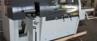
This is what a longitudinal planing machine looks like
After completing the processing action, the table returns to its original position. When idling, the support with the cutter moves to the side, making way for the table with the workpiece. Such turning is inherent in large parts, the weight of which can reach tens and hundreds of tons.
Machine Specifications
The two-column longitudinal planing machine model 7212 is designed for cutting long workpieces made of steel and various non-ferrous alloys. To increase productivity on the table, it is possible to process several workpieces simultaneously from one installation. This is done in cases where the total traction force applied to the table does not exceed acceptable limits. The equipment belongs to accuracy class H, and has the following technological indicators:
- Dimensions of the working space for the workpiece, maximum (length×width×height), mm – 1120×1250.
- Clear distance between racks, mm – 1350.
- Table dimensions (width×length), mm – 1120×
- Working range of longitudinal movements, mm – 900…1200.
- Traction force, per meter of length, kN – 200.
- The number of supports on the crossbar of the machine is 3: two are vertical, one is lateral.
- Maximum stroke value, m: horizontally – 1.875, vertically – 0.3.
- Maximum movement, m – 1.12.
- Rotation: yes, ±60°. Rotation accuracy ±1°.
- Crossbar travel in the vertical direction, m – 1.12.
- Installation speed of the cross member, mm/s – 20.76.
Workspace dimensions
For convenient and safe performance of production operations, the longitudinal planing machine is equipped with a device for continuously variable speed control and a stroke safety device in case of force overload (for the 7212 machine it is 120 kN). The retraction of the tool holder during the reverse movement of the unit is performed automatically.
The electrical circuit of the machine is quite complex, due to the presence of several electric motors:
- Main drive, 100 kW;
- Drive machine converters (for model 7212, the electrical circuit of the machine includes two such motors, 55 kW and 3 kW);
- Two motors that move the cross member and perform its braking (5.2 and 0.8 kW, respectively);
- Two motors that control the action of the calipers: vertical and lateral, 2.2 kW each;
- For fan drive, 0.8 kW;
- For powering generators and control drives, 4.9 kW.
All electric motors are powered from an alternating current network with a voltage of 380 V and a frequency of 50 Hz.
Download the manuals (passport) for the 7212 longitudinal planer
Among the main technical characteristics of the longitudinal planing machine are also:
- Possibility of adjusting feed values, mm - 0.25...12.5.
- The minimum value of the feed step, µm – 50.
- Speed of installation movements: in the vertical direction - 1.47 m/min, in the lateral direction - 0.735 m/min.
- The number of movement modes is two: 4...80 m/min - for direct and 12...80 m/min - for installation (idle) travel.
- Unit weight, t – 35.
Download album of drawings of machine 7212
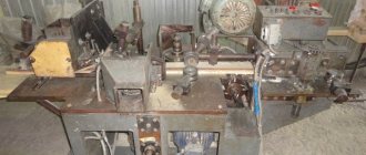
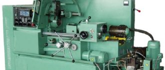
Cross planer
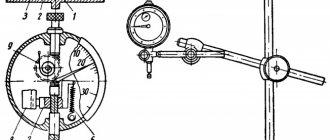
Landing and connecting bases of the cross-planing machine 7B35
More complex elements are processed on cross-planing units. This installation can operate both manually and according to a given program. The main moving part here is a support with a fixed cutter.
The workpiece is secured to the table using bolts or a vice. The table has the ability to move horizontally using crossbar guides.
Vertically, the table is fed by the crossbar itself, moving along the guides of the frame. The frame houses an electric motor and a gearbox that helps regulate the speed of the unit. Just like the longitudinal machine, the cross-planing machine has two strokes: working and idle.
Desktop view
Increasing the productivity of longitudinal planing (which is inferior in value to milling of similar products) is possible only by installing several semi-finished products of the same size on the table, technologically grouped according to the parameter of the amount of metal removal. This can increase processing productivity. In general, planing machines of the design in question are used for small-scale and single-piece production. Indications for the use of longitudinal planing technology are:
- impossibility of milling due to rapid wear of cutters, for example, with increased hardness of the surface of the product;
- possible thermal deformations of the part during its milling, when thermal deformation is likely, due to which the product loses its geometric dimensions required by the drawing;
- the presence at the enterprise of highly qualified workers capable of longitudinal planing of high-duty products with great accuracy;
- reduction of specific energy costs during processing, which has a positive effect on the cost of the final product.
Main elements of planing machines
- Bed. The main part of the machine, made of cast iron or steel.
- Table. Used to secure workpieces with bolts or a vice.
- Guides. Horizontal and vertical, along which the slider and table move.
- Caliper slider. Performs translational movements to cut and process the workpiece.
- Cutter. The main tool for metal processing.
- Caliper. Designed for fixing the cutter.
- Gearbox. Provides 6-speed transmission of spindle rotation.
- Vise. They are located on the work table to secure the workpiece.
- Electrical equipment.
Among the turning and metalworking industries, one of the most common cross-planing machines in the territory of the former USSR can be called the 7305 machine. Compactness and versatility in turning metal parts have led to its long-term serial production.
Successful modifications of the 7B35 and 7E35 units made it possible to significantly increase productivity. On the 7E35 metal planing machine, instead of a 6-speed gearbox, a mechanism with an 8-speed switch is installed.
Planing machine 7B35
Types of planing units
After analyzing the geometric dimensions of the workpiece, as well as the properties of the metal from which it is made, the surface finishing is carried out on a longitudinal or transverse planing unit.
The fundamental difference between these metal cutting machines is determined by the method of moving the cutter. A table moves on the longitudinal planing unit, with the workpiece fixed on it.
Large blanks are processed in this way. When cross planing is performed, the cutter moves and the workpiece is fixed on the table. This method is used when processing medium-sized parts. In each specific case, cutters of the appropriate configuration are selected.
The same class of metal processing equipment includes slotting, broaching and shaped-planing mechanisms.
Using cutters of various shapes, such machines perform operations of selecting recesses and grooves, turning channels and cutting holes.
One of the features of a metal planer is the number of cutting tools installed.
IMPORTANT TO KNOW: How does a CNC metal lathe work?
Some models are designed for simultaneous fastening of several cutters at once.
The following machine models are produced according to these parameters:
- one-sided;
- double sided;
- four-sided.
The more cutting tools installed on a planer-type device, the higher its productivity.
Construction of a longitudinal planing unit
As prescribed by the technical characteristics, longitudinal planing machines are used for processing surfaces on body and asymmetrical parts cast from cast iron or alloys of non-ferrous and ferrous metals.
The dimensions of the workpiece being processed are determined by the technical capabilities of the planing unit. The initial workpiece to be processed is placed on the table.
The table is capable of performing reciprocating movements. In this case, the cutter fixed in the support remains motionless.
When the table is idling, the support moves to the side, allowing the table to move freely to its starting point.
This complex movement allows you to process large workpieces with several cutters at once.
A longitudinal planing machine for the production of metal products is composed of a frame, a table, supports, a cross member, electrical equipment, a lubrication system and other components.
Each model has its own length and width of the working surface of the table. A common element for all models is the control panel.
When processing parts with complex geometric dimensions, several cutting tools can be installed on the support. This technique reduces the time for processing the product.
Design of a cross-planing unit
A cross-type metal planing machine is installed in production lines where small and medium-sized parts are processed.
The unit is used for planing horizontal, vertical and inclined surfaces.
As in any metalworking machine, the main elements of the cross-planing unit are the bed and the base.
IMPORTANT TO KNOW: CNC milling and engraving machines for metal
All components and devices that are designed to ensure fastening and movement of the corresponding elements are attached to this support. The part is fixed on the table at the specified coordinates.
The support, with the cutter fixed in it, is given movement within certain limits.
In the process of metal processing, parts assemblies and structural elements perform complex movements, the purpose of which is to carry out a given program.
The planing unit for metal of the cross type can operate under manual control or according to a given program.
The main one is the reciprocating movement of the slider on which the cutting tool is attached.
Auxiliary is the movement of the table on which the workpiece is fixed. The speed of movement of the slider is controlled using a special gearbox, like in a car.
Before processing any part, all mechanical components of the unit must be lubricated with machine oil.
Cutters of metalworking machines
A cutter is the main tool used in processing metal surfaces. The cutter is indispensable for turning, planing and slotting work.
Modern installations can be equipped with several cutters, which significantly speeds up the work process and affects the final quality of the product. The more cutters installed on the machine, the better for the future product.
Machine models differ in the possibility of multiple installation of cutters. Therefore, installations are divided into:
- one-sided;
- double sided;
- four-sided.
Geometric parameters of a planing cutter
The tool used directly affects the quality of cutting and the future product. Incisors differ radically in their properties. The material of the cutting base of the cutter (head) is especially important. No less important are the dimensions of the cutter shaft, as well as its shape. The tool is distinguished by type and the one that is needed for a particular job is chosen.
There are several such types:
- trimming;
- checkpoint;
- shaped;
- cutting;
- finishing
Planing cutters
Characteristics of species
For cutting metal, cutters are used, either solid or composite. Solid cutters are made entirely of steel or a special alloy. The components are equipped with a cutting plate attachment. The nozzle is attached to the rod by soldering, welding or mechanically. The types of materials for cutters are varied. Each of them has its advantages.
Tool steel. This includes carbon steel used at low cutting speeds. Alloy steel, the heat resistance of which allows the metal to be processed at higher speeds. High-alloy steel (high-speed) perfectly withstands high temperatures and has the best performance for cutting metal.
Hard alloys. Greater productivity than steel cutters can be obtained from tools made of hard alloys. They are metal-ceramic, among which the most productive are tungsten alloys, titanium-tungsten and titanium-tantalum-tungsten. Mineral-ceramic alloys have good heat resistance, but their use is limited due to the fragility of the material.
Elbor. Wear-resistant material for treating alloy steel surfaces. It is ideal for cutting metal due to several parameters, among which thermal resistance is the most valuable property of the material. It is used in industrial production for turning and grinding various alloys.
Elbor material in its own form
Diamond. This material has no equal in hardness. In industry, it has long been used for cutting and processing metals. Many knives, drills and other tools made of carbide are made using diamond-coated cutters on the cutting plane.
Classification of cutters for planing unit
Cutters that are used to process parts on metal planing machines are divided into categories according to the following criteria:
- cutting part material;
- shape and size of the rod;
- type of cutting tool.
The cutting part of the tool can be made entirely of high-speed steel or with a carbide nozzle. In the first case, the incisors are called solid, and in the second - compound.
Metal-ceramic alloys or mineral-ceramic materials are used as attachments for the cutting part. The holder of such a tool is made of structural steel.
Video:
High-speed bits are attached to the holder by welding, soldering or mechanically.
Depending on the shape of the head, the incisors can be retracted or curved. Depending on the direction of feed of the workpiece being processed, cutting tools are divided into right and left.
IMPORTANT TO KNOW: Operation of CNC milling machines for metal
The type of tool is determined by the type of specific operation.
The most common types are:
- checkpoint;
- finishing;
- trimming;
- cutting;
- shaped.
Planing of metal is performed only with the working movement of a cutter or table with a fixed workpiece.
When the cutting tool is secured in a folding holder, its wear occurs more slowly.
Because during the reverse stroke it tilts back and slides freely over the surface.