Information about the manufacturer of the screw-cutting lathe 1K62
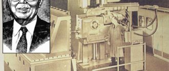
Manufacturer of the screw-cutting lathe model 1K62 - Moscow Machine Tools named after. A.I. Efremova , founded in 1857.
Machine tools produced by the Moscow Machine Tool Plant Krasny Proletary, KP
- 1A62
- universal screw-cutting lathe Ø 400 - 1K62
- universal screw-cutting lathe Ø 400 - 1K62B
- universal screw-cutting lathe with increased accuracy Ø 400 - 1K282
- eight-spindle vertical lathe Ø 250 - 1K620
- universal screw-cutting lathe with variator Ø 400 - 1K625
- lightweight screw-cutting lathe with an increased line of centers Ø 500 - 16A20F3
– CNC lathe Ø 400 - 16B20P
- high-precision screw-cutting lathe Ø 400 - 16K20
– universal screw-cutting lathe Ø 400 - 16K20M
- mechanized screw-cutting lathe Ø 400 - 16K20P
- high-precision screw-cutting lathe Ø 400 - 16K20F3
– CNC lathe Ø 400 - 16K20F3S32
– CNC lathe Ø 400 - 16K20T1
- lathe with operational control Ø 500 - 16K25
- lightweight screw-cutting lathe with an increased line of centers Ø 500 - 162
— universal screw-cutting lathe Ø 420 - 1730
— semi-automatic multi-cutting lathe Ø 410 - DIP-40 (1D64)
- universal screw-cutting lathe Ø 800 - DIP-50 (1D65)
- universal screw-cutting lathe Ø 1000 - DIP-200
– universal screw-cutting lathe Ø 400 - DIP-300
– universal screw-cutting lathe Ø 630 - DIP-400
– universal screw-cutting lathe Ø 800 - DIP-500
– universal screw-cutting lathe Ø 1000 - MK6046, MK6047, MK6048
- universal screw-cutting lathe Ø 500 - MK6056, MK6057, MK6058
- universal screw-cutting lathe Ø 500 - MK-3002
- table lathe Ø 220
Causes of turning errors on a 1K62 screw-cutting lathe
The following factors can affect the accuracy and purity of processing:
- Incorrect level installation of the machine on the foundation;
- The presence of a gap between the carriage clamping strips and the bed; the presence of a gap between the guides and wedges (it is necessary to tighten the clamping bars and wedges);
- Non-rigid spring mounting of the cutter;
- The part fixed in the chuck has a large overhang (it should be supported by a steady rest or pressed in with the center);
- The chuck faceplate is poorly secured, the chuck mounting screws are not tightened enough;
- Presence of dirt in the conical hole of the spindle;
- The mass of the chuck or workpiece is unbalanced (needs to be balanced);
- Incorrect cutting modes selected (high cutting speed or feed);
- The spindle bearings are not adjusted correctly. (for adjustments, see section “Adjusting the Machine,” page 43).
Adjustment of screw-cutting lathe 1K62
Adjusting the tension of the main drive belts
If over time there is a decrease in spindle torque, then since the machine has a V-belt drive from the main motor to the friction shaft, the belt tension should be checked. If the belts are not tensioned enough, they should be tightened. To do this, remove the lower casing covering the motor unit and loosen the nut securing the wedge pin of the vertical axis clamp of the plate, and the nut securing the sub-motor plate. By turning the round nut counterclockwise, lower the sub-motor plate to the required belt tension.The nuts must be tightened after adjustment.
Adjusting the friction multi-plate clutch
Friction reversible clutch of screw-cutting lathe 1k62
When the belt tension is sufficient, the main drive friction clutch should be adjusted to increase the spindle torque.
To do this, you need to turn off the main drive motor and remove the top headstock cover and the oil distribution tray.
By turning round nut 2 (Fig. 12), you can adjust the direct rotation clutch of the spindle, and by turning nut 3, you can adjust the reverse rotation clutch. To regulate the direct rotation clutch (handle 21 (see Fig. 5) is turned down, and to regulate the reverse rotation clutch it is turned up. In this case, the handle (see Fig. 5) must be tilted to the left (16:1 selection is turned on). Turn nuts can be installed only after latch 4 (see Fig. 12) is recessed into ring 5.
In most cases, it is enough to make 1/12 of a turn (one of the twelve grooves located along the periphery of the nut). You should ensure that the latch slides back into the groove of the nut, otherwise the latter may unscrew spontaneously.
If, after adjustment, turning on handle 21 (see Fig. 5) is difficult, then the clutch is too tight and the nuts should be loosened slightly.
Adjusting the band brake
Band brake of screw-cutting lathe 1k62
If, when the friction clutch is turned off, the spindle does not brake quickly enough, then the brake must be adjusted by tensioning the brake band 1 (Fig. 13) with nuts 2.
The spindle braking time depends on the amount of belt tension. At 2000 rpm, the spindle braking time without the product and chuck should not exceed 1.5 seconds.
When the spindle is in a locked position, lever 3 should be positioned symmetrically to the protrusion of the roller-rack 4, the position of which is secured by ball 5 with a control spring 6.
Adjusting the spindle bearings
Supports for the front and rear ends of the lathe spindle 1k62
The spindle bearing supports (front - double-row roller and rear - angular contact bearings) are adjusted at the factory and do not require any adjustment.
During repairs, the bearings are adjusted as follows. The front spindle bearing is adjusted by nut 8 (Fig. 18), located inside the headstock housing, in the following order: release screw 9 and turn the nut in the required direction. By turning this nut, axial movement is carried out (movement of the inner ring of the bearing 10 on the conical neck of the spindle
When the nut is turned to the right, the inner ring of the bearing is tensioned onto the conical journal of the spindle. In this case, the ring is deformed, its outer diameter increases, ensuring a tight fit of all rollers to the surfaces of the inner and outer rings of the bearing, which reduces the radial clearance in the bearing. After adjustment, tighten screw 9 again.
The axial clearance of the angular contact bearings of the rear spindle support is adjusted outside the headstock housing using a nut 11 through a thermal compensator 12. The tension is carried out by turning the nut to the right at an angle of 18..20° before the gaps are selected at the joints between the bearings and spacers. The outer rings are installed close to the stop using nut 13.
Repair cost
| Type of work | Price |
| Spindle Prevention | 9,000 rub. |
| Troubleshooting clamping devices | 19,000 rub. |
| Burnout (damage) of the stator winding | 30,000 rub. |
| Replacing bearings with rotor balancing | 50,000 rub. |
| Replacing spindle sensors | 10,000 rub. |
| Maintenance | 10,000 rub. |
| Non-standard work | 10,000 rub. |
| Major renovation | 50,000 rub. |
| Modernization of machine tools | 30,000 rub. |
Our main specialization is machine repair
If your machine does not work, our specialist will arrive as soon as possible and fix it. Call and consult by phone: 8
Technologies
Thanks to the use of modern devices, we can more accurately identify faults. And we save your money on repairs
Ideas
If your machine does not break down as usual. We will send it to our technicians and they will solve any problem
Speed.
You need the machine to work as quickly as possible. Our desires coincide.
Read useful information:
Turret machine repair
In case of significant breakdowns of the turret machine, a lot of difficulties can arise. In the article you can learn about the types of such equipment, as well as how to carry out repairs yourself and how much the help of specialists will cost.
Further
Causes of machine gearbox malfunctions, methods for eliminating them, cost
The article talks about common failures of the gearbox of a lathe. Their causes and ways to eliminate them yourself are described. The approximate cost of repairing a machine gearbox in Moscow is also given.
Further
Repair of coordinate machines
What is a coordinate machine? How to repair it yourself and is it worth it?
Further
Machine support repair
In the modern world, various machines are widely used, because... they allow you to perform many operations. This unit consists of many parts, where the main role is played by the machine support. And it often happens that the work of the tool freezes due to the breakdown of the caliper or other parts.
Further
Machine bed repair
The accuracy of its operation depends on the condition of the guide frames of turning equipment. Therefore, it is necessary to carry out timely repairs of equipment and its hotel elements.
Further
When concluding a long-term service agreement, you receive a discount of up to 20%. Don't forget, we have a guarantee on all types of work.
- engineer - mechanic
- CNC programmer
- Service engineer
- Electrician
- Electronics engineer
- Locksmith - repairman
Lubrication of screw-cutting lathe 1K62
Lubrication diagram for screw-cutting lathe 1k62
The durability of machine mechanisms largely depends on timely and high-quality lubrication of interacting parts. Before lubrication and startup, the machine is thoroughly wiped.
When the machine is operating, all parts of the mechanism and headstock bearings (Fig. 4) are lubricated by an automatically operating plunger pump 2.
A plunger pump, driven by an eccentric mounted on the friction shaft, supplies oil from a reservoir located at the bottom of the headstock housing, through a plate filter to the front spindle bearing and onto a tray, from where it spreads to the necessary mechanisms of the assembly.
After turning on the machine, a thin stream of oil should appear in the inspection eye located on the top cover of the headstock, indicating normal operation of the pump. If a trickle does not appear, it is necessary to remove the upper headstock cover and, using a stop screw screwed into the drive lever, adjust the normal operation of the pump.
The oil level in the reservoir should be checked daily before starting work. If, when the machine is stopped, the oil level is below the oil indicator mark located on the left side of the headstock, it is necessary to add oil to the reservoir. When the machine is turned on, the oil level in the reservoir decreases, as some of the oil circulates in the system. This does not require additional oil filling.
When changing the oil, remove the oil drain plug located in the oil indicator.
It is recommended to change the oil immediately after turning off the machine, when all wear particles and dust are suspended and removed along with the used oil.
Before filling the housing again with oil, thoroughly rinse and clean the headstock to completely remove any settled dirt. It is unacceptable to use cleaning materials with loose fibers for cleaning.
Fresh oil should be added only after the assembly has been thoroughly dried.
The feed box is lubricated by plunger pump 3 located in the upper part of the housing. The proper operation of the pump can be monitored through the inspection eye located on the front cover of the feed box. To control the oil level, there is an oil indicator located under the sight glass.
Oil is poured into the upper part of the feedbox reservoir. The oil drain plug is located in the bottom wall of the housing.
The plunger pump 4 in the apron is mounted in the bottom cover and is driven by the eccentric of the worm gear shaft. It provides lubrication to all drive parts, bearings and guides of the caliper and carriage.
The oil supply to the caliper and carriage guides is turned on using valve 10.
It is recommended that at the beginning of the shift, set the valve to position “0” (open) and run the carriage along the frame and the lower part of the support along the carriage at high speed two or three times. After this, the tap should be returned to position “3” (closed).
If the valve remains in position “0” (open) while the machine is operating, then all the oil from the apron reservoir will be pumped out during the shift.
Oil is filled through a hole in the left wall of the apron, closed with a plug.
There are two oil drain plugs in the lower apron cover. The transverse and longitudinal feed screw of the caliper and their supports, as well as the axis of the cutting head, are lubricated with grease nipples 7, 11, 12, 13.
Lubrication of the supports of the eccentric shaft of the quill and the tailstock screw is carried out through grease fittings 5, 8, 9, 14; The bearings of the lead screw and the lead shaft are lubricated through a hole closed by plug 6.
During operation of the machine, it is necessary to monitor the operation of the oil pumps and the presence of oil in the tanks. Oil characteristics and lubrication intervals are indicated in the lubrication chart.
Lathe 1k62 b device repair adjustment
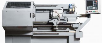
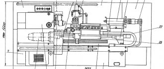
Machine 1k62: description, design, operation
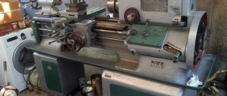
The 1k62 screw-cutting lathe was one of the most common in the Soviet Union. This device can still be seen in workshops. The main advantages of 1k62 are reliability in operation, good productivity, endurance, and the ability to process large workpieces.
1k62 lathes have been used since the thirties of the last century. They were developed on the basis of . Used to work with parts made of various materials.
Equipment history
The 1k62d lathe is a modern, improved version of the old machine. The Soviet abbreviation DIP, which designated devices of that time. After this, the markings included numbers indicating the height above the bed. The turning equipment was equipped with gearboxes. In 1956, a new model appeared, which became known as 1K62. It is distinguished from the previous one, 1D62, by a number of improvements:
- 1K62 has an electric pump that supplies coolant;
- the new model is equipped with a more powerful engine;
- there is a reverse mechanism that is used to create threads;
- a new V-belt drive was installed;
- the new model has a reinforced friction clutch;
- 1K62 is equipped with three spindle rotation handles.
This is not all of the improvements listed. Nowadays, not only 1K62 is used in production. An even more improved model has appeared - 1K625.
Overview of the device and its scope of use
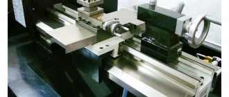
When a new model of the 1k62 turning machine appeared in 1956, it was produced until 1971. It has a high-rigidity spindle, which is mounted on special bearings. As a result, it became possible to process products made of hardened steel. Shock loading is allowed. However, it does not at all affect the quality or accuracy of processing. The new equipment has a number of undeniable advantages:
- large speed range;
- powerful engine;
- low level of vibration during operation;
- knot stiffness.
As a result, precision machining of metal parts became available. The new device is a frontal one. It can work with any workpieces that have a large diameter but a short length.
The machine has a transverse adjustment on the rear beam. This allows you to work with shallow cones. When the beam is connected to the bottom of the support, it allows for increased functionality during drilling operations.
Design Features
“Red Proletarian” has not existed for a long time, but many of the devices that it managed to release still work to this day. Over time, many parts wear out and need to be replaced. And to give a 1k62 screw-cutting lathe a marketable appearance, sometimes it is enough just to tint its body. The main thing is that maintenance is performed regularly.
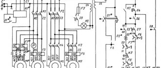
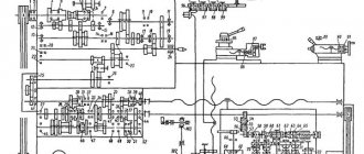
Some devices require reworking of the electrical circuit and kinematics. Sometimes you need to change electrical equipment, after which the device will function normally for quite some time. However, for repairs you will need detailed technical documentation, an electrical diagram, and a kinematic diagram.
The device assumes the ability to install two types of steady rests for the 1k62 lathe: fixed ones with a diameter of 20 to 120 mm and movable ones with a diameter of 20-90 mm. For operation, a 23-speed engine with a power of 10 kW is used with a maximum speed of 2000 per minute. This allows you to select a convenient mode for processing hard metals.
The operating instructions contain information on adjusting the spindle speed and how to set the support feed box of the 1k62 machine. The box is controlled by levers, and the gears are replaceable. Weight – 2250 kilograms, dimensions – 250x120x150 cm.
Its characteristics indicate that an additional motor with a power of one thousand watts is responsible for feeding the caliper in the 1k62 feed box. The electrical circuit contains a thermal relay that protects the motors from overheating. To protect against short circuits, the circuit includes fuses.
There are two types of unit modifications. This is a 1k62D screw-cutting lathe, characterized by a spindle hole enlarged by ten millimeters. The 1k62 and 1k62D feedbox, kinematics, as well as other components of these models are almost identical.
The 1k62 circuit diagram of this unit is very different from the modern version 1k625. In this modification, the weight and processing diameter over the support and bed are slightly increased. The carriage travel is also increased. The diagram of the 1k62 machine indicates that the engine power, functionality, and speed of rotation in this version did not undergo significant changes.
Modernization
Turning equipment manufactured using the 1K62 template has been significantly improved. The parts are made of durable alloys, which are very different from the previous ones. The electrical circuit has been changed.
Modifications have become more reliable, having different powers. The safety of electric drives and networks is high. The new models are distinguished by ergonomics, which does not require much effort to start or stop the equipment. Improved models begin to work smoothly after switching on. The same applies to turning off.
Now the machines can produce even higher quality parts with high precision. This was made possible thanks to the cast iron frame, which has ideal rigidity. The work of turners has become much easier.
Advantages
1k62, the characteristics of which are described above, and the 1k62d screw cutting machine belong to the frontal type class. The technical characteristics of 1k62 machines make it possible to process parts made of hardened metals. 1k62, the passport of which can be downloaded on the Internet, has other advantages:
- vibration resistance;
- possibility of using carbide cutters;
- versatility in work;
- large speed range;
- high strength of all parts.
What is produced in 1Q62?
The capabilities of the equipment are great (you can additionally watch a video about them on the Internet). The equipment can now freely process parts with a small diameter, low weight, or vice versa – huge ones. The weight of the workpiece can reach up to 300 kilograms, and when the product is secured in the centers - up to 1200 kilograms.
As a result, the product acquires the desired shape and structure, according to the drawings. 1k62 machines, the technical characteristics of which are described above, can be effectively used for high-strength workpieces made of hardened metal. Bearings provide the required rigidity. They are easy to make carvings of any complexity.
Safety precautions
When operating any equipment, there is a certain set of safety rules. Lathes, like milling machines and others, are quite dangerous to use.
i-perf.ru
Technical data and characteristics of the screw-cutting lathe 1K62
| Parameter name | DIP-200 (1d62m) | 1A62 | 1K62 | 16K20 |
| Main settings | ||||
| Accuracy class according to GOST 8-82 | N | N | N | N |
| The largest diameter of the workpiece processed above the bed, mm | 410 | 400 | 400 | 400 |
| The largest diameter of the workpiece processed above the support, mm | 210 | 210 | 220 | 220 |
| Maximum length of workpiece processed in centers (RMC), mm | 750, 1000, 1500 | 750, 1000, 1500 | 710, 1000, 1400 | 710, 1000, 1400, 2000 |
| Maximum turning length, mm | 650, 900, 1400 | 650, 900, 1400 | 640, 930, 1330 | 645, 935, 1335, 1935 |
| Height of the center axis above the flat guides of the frame, mm | 202 | 215 | 215 | |
| The greatest distance from the axis of the centers to the edge of the tool holder, mm | 228 | 228 | 240 | |
| Height from the supporting surface of the cutter to the axis of the centers (cutter height), mm | 23 | 25 | 25 | 25 |
| The largest cross-section of the cutter holder, mm | 25 x 25 | 25 x 25 | 25 x 25 | 25 x 25 |
| Maximum mass of workpiece processed in the chuck, kg | 500 | 200 | ||
| Maximum mass of workpiece processed in centers, kg | 1500 | 460, 650, 900, 1300 | ||
| Spindle | ||||
| Diameter of through hole in spindle, mm | 38 | 36 | 38/ 47 | 52 |
| The largest diameter of the rod passing through the hole in the spindle, mm | 37 | 34 | 36/ 45 | 50 |
| Number of speed steps for direct spindle rotation | 18 | 21 | 24 | 24 |
| Spindle rotation speed in forward direction, rpm | 11,5..600 | 11,5..1200 | 12,5..2000 | 12,5..1600 |
| Number of spindle reverse rotation frequency steps | 9 | 12 | 12 | 12 |
| Spindle rotation speed in reverse direction, rpm | 18..760 | 18..1520 | 19..2420 | 19..1900 |
| Size of the internal cone in the spindle, M | Morse 5 | Morse 5 | Morse 5/6 | Morse 6 |
| Spindle end flanged | M90x6 | M90x6 | M90x6/ 6 | 6K according to GOST 12593-72 |
| Spindle braking | There is | There is | There is | |
| Spindle material | Art.45 | Art.45 | ||
| Caliper. Submissions | ||||
| Maximum movement of the longitudinal carriage of the caliper by hand, mm | 650, 900, 1400 | 650, 900, 1400 | 640, 930, 1330 | |
| Maximum movement of the longitudinal carriage of the caliper along the roller and along the screw, mm | 650, 900, 1400 | 650, 900, 1400 | 640, 930, 1330 | 645, 935, 1335, 1935 |
| Maximum movement of the transverse carriage of the caliper by hand, mm | 280 | 280 | 250 | 300 |
| Maximum movement of the transverse carriage of the caliper along the roller and along the screw, mm | 280 | 280 | 250 | |
| Longitudinal movement per dial division, mm | No | 1 | 1 | 1 |
| Transverse movement per dial division, mm | 0,05 | 0,05 | 0,05 | 0,05 |
| Transverse movement per one revolution of the dial (transverse caliper screw pitch), mm | 5 | 5 | ||
| Number of longitudinal feed stages | 35 | 35 | 49 | |
| Limits of longitudinal working feeds, mm/rev | 0,082..1,59 | 0,082..1,59 | 0,07..4,16 | 0,05..2,8 |
| Number of cross feed stages | 35 | 35 | 49 | |
| Limits of working cross feeds, mm/rev | 0,027..0,522 | 0,027..0,522 | 0,035..2,08 | 0,025..1,4 |
| Speed of fast movements of the caliper, longitudinal, m/min | No | No | 3,4 | 3,8 |
| Speed of fast movements of the caliper, transverse, m/min | No | No | 1,7 | 1,9 |
| Maximum permissible speed when working on stops, m/min | 0,25 | |||
| Number of metric threads to be cut | 25 | 19 | 44 | |
| Limits of metric thread pitches, mm | 1..12 | 1..12 | 1..192 | 0,5..112 |
| Number of inch threads to be cut | 30 | 20 | 38 | |
| Limits of pitches of inch threads, threads/inch | 24..2 | 24..2 | 24..2 | 56..0,5 |
| Number of modular threads to be cut | 12 | 10 | 20 | |
| Limits of modular thread pitches, module | 0,25..3 | 0,5..3 | 0,5..48 | 0,5..112 |
| Number of cut pitch threads | 24 | 24 | 37 | |
| Limits of pitches of cut pitch threads | 96..7 | 95..7 | 96..1 | 56..0,5 |
| Longitudinal switch stops | There is | There is | There is | There is |
| Transverse switching stops | No | No | No | |
| Overload protection | There is | There is | There is | There is |
| Blocking the simultaneous activation of longitudinal and transverse movement of the caliper | There is | There is | There is | There is |
| Thread indicator | No | |||
| Outer diameter of lead screw, mm | 40 | 40 | ||
| Lead screw pitch, mm | 12 | 12 | ||
| Running shaft diameter, mm | 30 | 30 | ||
| Cutting slide | ||||
| Maximum movement of the cutting slide, mm | 100 | 113 | 140 | 150 |
| Movement of the cutting slide by one division of the dial, mm | 0,05 | 0,05 | 0,05 | 0,05 |
| Movement of the cutting slide per one revolution of the dial (screw pitch of the cutting slide), mm | 5 | 5 | ||
| Maximum angle of rotation of the cutting slide, degrees | ±45° | ±90° | ±90° | ±90° |
| Scale division of the tool slide rotation scale, deg | 1° | 1° | 1° | 1° |
| Number of cutters in the cutting head | 4 | 4 | 4 | 4 |
| Tailstock | ||||
| Tailstock quill diameter, mm | 65 | 70 | ||
| Cone of the hole in the tailstock quill according to GOST 2847-67 | Morse 4 | Morse 4 | Morse 5 | Morse 5 |
| Maximum movement of the quill, mm | 150 | 150 | 150 | 150 |
| Movement of the quill by one division of the dial, mm | No | No | 0,05 | 0,1 |
| The amount of lateral displacement of the headstock body, mm | ±15 | ±15 | ±15 | ±15 |
| Electrical equipment | ||||
| Number of electric motors on the machine | 1 | 2 | 4 | 4 |
| Main drive electric motor, kW | 4,3 | 7 | 10 | 11 |
| Electric motor for fast movements, kW | No | No | 0,8 | 0,75 |
| Electric motor of hydraulic station, kW | No | No | 1,1 | 1,1 |
| Cooling pump electric motor, kW | No | 0,125 | 0,125 | 0,12 |
| Cooling pump (pump) | PA-22 | PA-22 | PA-22 | |
| Dimensions and weight of the machine | ||||
| Machine dimensions (length width height) (RMC = 1000), mm | 2650 x 1315 x 1220 | 2650 x 1580 x 1210 | 2812 x 1166 x 1324 | 2795 x 1190 x 1500 |
| Machine weight (RMC = 1000), kg | 1750 | 2105 | 2140 | 3005 |
Causes of machine gearbox malfunctions, methods for eliminating them, cost
In order to understand well what kind of breakdown occurred in the machine and how to fix it yourself, you need to know the structure of the machine.
What parts does it consist of and what functions do they perform? Types of breakdowns
1. When the motor is turned on, torque does not flow to the spindle.
Causes:
- The key on the wheel or coupling has been cut;
- the discs on the friction clutch have worn out;
- the pin on the safety clutch has been cut off;
- there was a violation of the movement adjustment on the axis of the gears or blocks.
2. Speeds stopped switching
Causes:
- The key or pin with which the handle, fork or gear sector is attached to the control has been cut;
- the fork or gear shift lever has broken down;
- the keyway on the gear shift lever is worn out;
- the end of the teeth on the wheel became clogged.
3. It is difficult to switch gears
Causes:
- The shaft is bent or twisted;
- formation of burrs, nicks on the shaft, splines and keys;
- differs from the required fit of the wheels of the mechanism or block on the shaft.
4. When turning on the speed, the shafts in the box do not turn
The reason is the simultaneous inclusion of two speeds.
5. Spontaneous shutdown of speeds
Causes:
- The mating wheels have not completely locked teeth;
- a force occurs on the axle when the wheel teeth engage, due to the fact that the shafts are not parallel;
- the clamp spring has weakened;
- spacing of holes for the clamp.
6. The box heats up more than 50 degrees
Causes:
- There is no gap between the teeth on the wheel;
- there is little lubrication in the system, the overpasses for supplying lubrication are clogged;
- Shaft bearings are too tight.
7. There is no movement of the working body related to the feed mechanism during switching on
Causes:
- The safety clutch setting has gone wrong;
- wear of the half coupling;
- sheared off the coupling key.
8. Automatic shutdown of the feed mechanism
Causes:
- Weakening of the spring on the clamp;
- spacing of holes for the clamp.
9. Feed acceleration stopped working
The reason is that the acceleration clutch has failed.
10. The lead screw or lead shaft does not turn on
The reason is a malfunction in the locking mechanism.
DIY repair
Repair of some elements on the machine is carried out independently. It is also not difficult, with certain skills and knowledge, to repair the gearbox on a machine.
1. Actions when the supply of torque ceases:
- Replace the key;
- adjust the gap between the couplings;
- change the pin;
- adjust the movement on the axis.
2. If gear shifting fails:
- Change the key or pin;
- replace the plug with a new one or repair it;
- make a groove;
- file the ends of the teeth.
3. When it is difficult to switch gears:
- Bend the shaft to its original state;
- remove burrs and nicks;
- grind the shaft.
4. If the rotation of the shafts in the box stops, repair the locking mechanism.
5. If the speeds turn off spontaneously:
- Adjust so that the teeth touch along the entire length;
- bore or install repair bushings for the shaft bearings to achieve parallelism;
- adjust or replace the spring;
- change the spare part on which the holes for the latch are located or replace the latch itself.
6. If the box overheats:
- Grind the teeth or change the wheels themselves with teeth;
- clean the lubrication system, add lubricant to the required level;
- release the tension.
7. If the movement of the working body of the feed mechanism fails:
- Adjust or replace the spring;
- replace or repair the coupling half;
- change the key.
8. In case of unauthorized shutdown of the feed mechanism:
- Adjust or replace the spring;
- correct the hole by replacing the pin.
9. When the feed acceleration stops, adjust or repair the coupling.
10. If the lead screw or shaft does not turn on, adjust or repair the mechanism.
Service
The gearbox is serviced together with the entire machine. Change the oil as specified in the lubrication chart. Before changing the oil, you need to monitor its quantity. Before work, all grease fittings must be filled with lubricant. You also need to monitor the cleanliness of the oil purifying filter and change it on time. In a box, due to the intensive work of the machine and the box itself, play may occur between the parts. It can cause inaccuracy in the operations performed and cause the box to break. If play is detected, it is necessary to eliminate it using adjustments or replacing worn parts. There should be no metal shavings in the gearbox tray. Oil must flow into the box continuously. At the end of the work, the machine must be cleaned of chips, lubricated and turned off.
Price
The cost of repairing a gearbox depends on the city where the repair is carried out and on the brand of the machine.
Cost of repairs in Moscow
Inspect the friction shaft, replace bearings and worn parts:
- Lathe model 16k20, 1k62 - 14,000 rub. (price does not include spare parts).
- Lathe model 1m63 - 24,000 rub.
Replacing spindle bearings:
- Model 16k20, 1k62 — 18,000 rub.
- Model 1m63 - 26,000 rub.
Repair and overhaul, replacement of bearings and worn parts:
- Model 16k20, 1k62 - from 16,000 rub.
- Model 1m63 - from 20,000 rub.
If knowledge and experience in repairing the machine gearbox is not enough, then it is better to entrust this process to specialist service technicians. Otherwise, illiterate actions can lead to machine breakdown or settings failure.