SETTING UP A SCREW-CUTTING LATHE WITH A FEED BOX FOR THREADING
1. Setting up a 1K62 screw-cutting lathe for cutting threads with a pitch of P = 1 mm
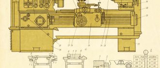
1.1. In the table of 5 threads and feeds of the 1K62 machine (Fig. 1), which is mounted on drum E, threads with a pitch of 1 mm are highlighted with a bold quadrangle. To set up the machine for a given pitch of the thread being cut, first pull disk 5 towards you by the two handles. Then rotate it to a row in 1mm increments. Combine notch B of disk 5 with notch B of table 5. Replaceable guitar gears - 42:50. Then turn drum b (Table 4) until it aligns with the “Metric thread” column. Set handle 3 to position B (normal step) (Table 3), and handle 4 to position D (normal step right) (Table 1).
1.2. On the guitar, check the 42:50 replacement gears. Pull the “Rack gear off” handle 1 on the caliper apron towards you (Fig. 2). Check machine settings.
2. Checking the settings of a screw-cutting lathe for cutting threads with a pitch of P = 1 mm
Set the machine to minimum spindle speed. Move the caliper towards the tailstock. Turn on the spindle rotation by connecting the split nut of the lead screw, and turn off the spindle rotation.
On the headstock and chuck, draw a horizontal line with chalk, and at the back of the carriage on the bed guides, draw a line in the transverse direction with a pencil. Turn on the machine and manually make 10 spindle revolutions so that the horizontal lines drawn on the headstock and the chuck coincide. At the back of the carriage, draw a second line with a pencil, disconnect the split nut, and move the caliper towards the headstock. Measure the resulting distance between the two marks (10 mm) and divide it by the number of spindle revolutions (10), we obtain the pitch of the thread being cut equal to 1 mm. Consequently, the feed box is configured correctly, since in one revolution of the spindle the cutter fixed in the tool holder will travel a distance of 1 mm equal to the pitch of the thread being cut. Check the machine settings with a thread gauge after a test run of the thread being cut with a thread cutter on a defective workpiece.
Source
Calculation of kinematic settings of screw-cutting lathes 1K62 and 1K625
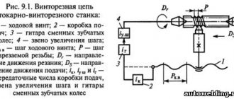
Setting up kinematic chains when performing various works on screw-cutting lathes comes down to selecting the gear ratios of gearboxes, feeds and other mechanisms, which is carried out by switching the corresponding levers. An exception is the cutting of particularly precise threads or threads with non-standard pitches. The final link of the thread-cutting chain is the lead screw 68 (see Fig. 9) and the uterine nut, therefore the adjustment equation according to equalities (5) and (9) can be written in the following form (keeping in mind the single-thread nature of the screw)
1 spindle revolution i x tB = tH, (11)
i is the gear ratio of the kinematic chain from the spindle to the lead screw.
tН is the pitch of the thread being cut;
Brief history of the series
- The first screw-cutting lathes with a gearbox were produced and called DIP 200,
- DIP 300 and so on. The letters meant “Catch up and overtake”, and the numbers meant the height above the bed.
- ENIMS adopted a unified system of machine symbols. According to the DIP 200 system, it began to be called 1D62, and accordingly its modifications changed their names.
- Soon the first DIP 200 models appeared, called 1D62,
- 1D62M. These models were then replaced by a newer one - 1A62. The 1A62 was produced for several years, after which it was replaced by the 1K62, which was produced for another eighteen years. Modifications were produced by 1K62.
- Then the 16B20P entered production, which was a transitional model between the two machines.
- After another six years, the first 16K20 were produced. The machines gradually began to produce less and less. They began to be modified, but the modifications were not long-lasting.
- Seventeen years after the first 16K20 they were replaced by machines of the MK series: MK6046, MK6047.
Tailstock of screw-cutting lathe 1K62
The tailstock has a plate 12 (Fig. 11) and can move along the bed guides. In the hole of the tailstock housing 3 there is a retractable quill 6, which moves using a flywheel 10 and a screw pair 7-8. The handle 5 fixes a certain overhang of the quill, and with it the rear center 4. The body 3 of the headstock, with the help of a screw pair 1, can be shifted in the transverse direction relative to the plate 12. With a bolt 14 and a shoe 2, the tailstock can be secured to the machine bed. This can also be done using handle 9, eccentric 11 and shoe 13. In the conical socket of the quill, you can install not only the rear center, but also a cutting tool for processing holes (drill, countersink, etc.).
Drawing of the tailstock of a screw-cutting lathe 1K62
Purpose and scope of application of a metal screw-cutting lathe
The 1K62 lathe is universal and is used for finishing and semi-finishing turning tasks. They cut left and right threads: metric, inch.
Used for processing hardened workpieces because the spindle provides rigidity to the machine. It produces high-quality cuts with carbide tools due to the large speed range of 1K62.
The device is frontal and it processes short workpieces of large diameter. The machine processes flat cones, because its rear beam can move.
1K62 universal screw-cutting lathe. Purpose, scope
The universal screw-cutting lathe 1K62 began to be produced by the plant in 1956 and replaced the outdated model 1A62 in production. In 1971, the machine was replaced by a more advanced model 16K20.
1K62 screw-cutting lathe is designed to perform a wide variety of turning operations, including cutting threads: metric, inch, modular, pitch and Archimedean spiral with a pitch of 3/8″, 7/16″; 8; 10 and 12 mm.
1K62 lathe can be classified as a frontal lathe, because it allows the processing of relatively short workpieces with large diameters.
The operating conditions of the machine are UHL-4 according to GOST 15150-69.
The front end of the spindle is made in accordance with GOST 12593 (Flanged spindle ends for a rotary washer and clamping device flanges) (DIN 55027, ISO 702-3-75) for a rotary washer, with a centering short cone 1:4 (7°7′30″). Until 1962, the 1k62 lathe was produced with a threaded spindle end M90 x 6.
The spindle is mounted on two rolling bearings. The front support is an adjustable double row roller bearing with an internal tapered ring. The bearing is adjusted by tightening the nut (stopper), which presses on the inner race of the bearing. At the same time, the ring slides onto the conical neck of the spindle and unclenches; This reduces the gap between the rings and rollers caused by wear. The rear spindle support consists of two angular contact bearings, which are adjusted only during routine inspection of the machine.
1K62 lathe includes special bearings for mounting the spindle, which ensures the required rigidity and high precision of workpiece processing. According to GOST 8-82, the 1K62 lathe belongs to accuracy class N. Machining accuracy will be ensured even under shock loads.
steady rests can be installed on the 1K62 : movable, with an installation diameter of 20-80 mm, and stationary, with an installation diameter of 20-130 mm.
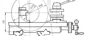
The longitudinal movement of the carriage of the 1K62 can be limited by a special stop installed on the front shelf of the frame. Thus, with the stop installed, the speed of movement of the caliper cannot exceed 250 mm/min.
1K62 screw-cutting lathe, an additional asynchronous motor is used. Its power is 1.0 kW at a rotation speed of 1410 rpm.
1K62 lathe is equipped with thermal relays that protect motors from long-term overloads, as well as fuses that protect against short circuits.
The lathe can use a three-jaw self-centering chuck with a diameter of 250 mm or a four-jaw chuck with a diameter of 400 mm.
Main technical characteristics of screw-cutting lathe 1k62
Developer: Moscow Machine Tool Plant Red Proletarian.
Manufacturer: Moscow Machine Tool Plant Red Proletarian. Serial production from 1956 to 1971.
A total of 202 thousand machines were produced.
The main parameters of the machine are in accordance with GOST 18097 . Screw-cutting and turning machines. Basic dimensions. Accuracy standards.
- The largest diameter of a Disk-type workpiece processed above the bed is Ø 400 mm
- The largest diameter of the Shaft type workpiece processed above the support is Ø 220 mm
- Distance between centers - 710, 1000, 1400 mm
- Center height - 215 mm
- Electric motor power - 7.5 or 10 kW
- Full machine weight - 2.0; 2.1; 2.2 t
Spindle of screw-cutting lathe 1k62
- The end of the spindle is flanged with a short taper . The nominal size of the spindle end is 6 according to GOST 12593
- Internal (tool) spindle cone - Morse 6
- The end of the spindle until 1962 was threaded M90 x 6 mm with a centering belt Ø 92 mm. Inner cone - Morse 5
- The diameter of the through hole in the spindle is Ø 47 mm
- The largest diameter of the processed rod is Ø 45 mm
- Limits of direct spindle revolutions per minute (24 steps) - 12.5..2000 rpm
- Limits of spindle reverse revolutions per minute (12 steps) - 19..1900 rpm
- Standard chuck diameter - Ø 200, 250 mm
Feeds and threads of screw-cutting lathe 1k62
- Limits of longitudinal feeds - (49 steps) 0.07..4.16 mm/rev
- Transverse feed limits - (49 steps) 0.035..2.08 mm/rev
- Limits of metric thread pitches - 1..192 mm
- Limits of modular thread pitches - 0.5..48 modules
- Limits of inch thread pitches - 24..2 threads per inch
- Limits of pitch thread pitches - 96..1 pitches
Modifications of screw-cutting lathe 1k62
- 1k62 - basic model of a universal screw-cutting lathe Ø 400 x 710, 1000, 1400 mm;
- 1k62t - especially high precision screw-cutting lathe Ø 400 x 1000;
- 1k62B - high-precision high-speed screw-cutting lathe Ø 400;
- 1k62m - mechanized copying lathe Ø 400 x 500;
- 1k620 - screw-cutting lathe with variator Ø 400;
- 1k625 - lightweight screw-cutting lathe Ø 500 x 1000, 1400, 2000 mm.
History of the series of screw-cutting lathes from DIP-200 → 1a62 → 1k62 → 16k20 → MK6056
In 1930, the Moscow Machine Tool Plant decided to develop a new standard lathe, abbreviated as TS. Somewhat later it was renamed DIP-200 - Let's Catch Up and Overtake
, according to the main slogan of the first five-year plan, where 200 is the height of the centers above the frame.
from the German company VDF was chosen as a prototype .
In April 1932, preparations began for the release of the first batch of DIP-200 machines. On April 25, 1932 , the first Soviet universal screw-cutting lathe with a gearbox, DIP-200, was assembled and tested. By the end of 1932, 25 DIPs were produced.
In 1934, production of machines DIP-300, DIP-400, DIP-500 was mastered. Subsequently, the production of these machines was transferred to the Ryazan Machine Tool Plant. The production of the DIP-500 machine was also transferred to the Kolomna Heavy Machine Tools Plant KZTS.
In 1937, ENIMS developed a type (nomenclature of types and sizes) of machine tools and adopted a unified system of machine symbols. According to the new designation system, the first DIP-200 became known as 1D62
. But the abbreviation DIP-200 has been preserved to this day - to designate a lathe with a center height above the bed equal to or close to 200 mm.
In 1940, the plant produced the 162K (26A) machine - one of the DIP-200 variants.
In 1945, the plant switched to production of the modernized DIP-200 machine (DIP-20M, 1d62m).
In 1948 , the plant switched to production of the 1A62 machine.
In 1949-1953, without stopping production, the transition to continuous production of the 1A62 lathe was carried out. Also produced over the years: 1620, 1B62, 1m620, 1622.
Main varieties and explanation of modifications
The first 1K62 was released on and went through a long journey, with many modifications.
The main varieties were: 1K625, 1K620, 1K62B. The modifications have decodings, each number and letter has a meaning:
- The number 1 means that the machine is a lathe.
- The letter K indicates the generation of the device.
- The number 6 indicates that the machine is a screw-cutting lathe.
- Number 2 indicates the height of the centers.
- The numbers 25 at the end indicate the maximum diameter of the workpiece above the caliper.
- The numbers 20 are the height of the centers above the bed.
- The letter B is the value of the change in the main model.
This is what the main modifications look like, their decoding 1K62.
Specifications
The main technical characteristics are:
- The machining diameter above the caliper is two hundred mm.
- The distance between centers is one thousand mm.
- Electric motor power - 10 kW
- The weight of the machine is 3035 kg.
- The transverse displacement of the housing is approximately fifteen mm.
Main settings
The main parameters are called: the distance between centers, which is a thousand millimeters, the weight of the machine is two tons.
The spindle speed limits in the forward direction reach 2 thousand revolutions per minute, in the reverse direction up to 1900 revolutions per minute. The diameter of the cartridge is 250 millimeters.
Spindle
Spindle is a shaft that has right and left turns of rotation. The spindle is installed to hold tools as well as workpieces. Consequently, a clamping chuck or other elements are attached to it. It depends on the device.
Caliper and feed
The support is designed to move, fixed in the tool holder, along and across the spindle axis. It consists of three main units - the carriage, the cross slide, and the tool slide of the caliper. In technical literature they may be called differently.
The feed box is used to switch the rotation speed of the lead screw and shaft, that is, to select the feed speed of the cutter along the spindle axis. A gearbox is usually located inside the box.
The gearbox is made of gears that shift. The input feed shaft receives torque from the spindle. Before doing this, it goes through the guitar.
Cutting slide
The cutting slide is one of the main components of the caliper. They are installed at an angle to the center line of the machine centers. The cone is processed by manually moving the cutting slide. This method allows you to process internal and external cones with any slope angles.
Tailstock
The headstock is a unit that is used in many metal-cutting machines. The headstock accurately supports and moves the part relative to the tool that cuts it. Usually it is located, mounted on the frame. There are three functions:
At the back, the assembly has a tapered hole for installing the center. The center supports the workpiece and is used to secure the tool.
Apron design for a universal screw-cutting lathe
The apron of the screw-cutting lathe is rigidly attached to the front end of the caliper carriage.
The apron converts the rotational movement of the lead screw or lead roller into translational movement of the caliper (feed) along the bed guides. The movement from the running roller is also used to mechanically move the cross slide.
Technical characteristics, photographs and drawings are given on the page Screw-cutting lathe 1K62 .
A lead screw is used when cutting threads. The rotary motion of the lead screw is converted into a translational motion of the caliper (feed motion) using a split nut. The rotation speed of the lead screw, and therefore the feed rate, is controlled by the feed box of the lathe.
The roller is used for all other turning operations. The rotational movement of the running roller is converted into a translational movement of the caliper (feed movement) using a worm on a sliding key, a gear rack mounted on the frame and a gear engaged with the rack. This wheel can be rotated either mechanically - from the drive shaft, or manually from the rotation of the handle (handwheel).
Mechanisms in the apron can convert the rotational motion of the roller into translational motion (mechanical feed) of the caliper cross slide.
To accelerate the movement of the caliper, a separate electric motor is used, which rotates the roller at an increased speed.
A plunger pump provides lubrication of all drive parts, bearing supports and guides of the caliper and carriage. It is mounted on the lower cover of the apron and is driven by the worm gear shaft.
The lead screw is lubricated using a manual oiler with the nut on.
General design and operating principle
The design features regulatory bodies that are familiar to experts, and a simple control scheme is used. The model consists of nodes:
- bed;
- front, rear cabinets;
- headstock;
- chuck;
- tailstock;
- tool holder;
- apron with caliper feed mechanics;
- drive shaft;
- gearbox.
The design is designed for high vibration resistance and rigidity. The base is pedestals, and to increase their rigidity, vertical ribs are used on the walls.
On the left side of the unit there is a headstock, inside it is a gearbox, a spindle with a chuck. On the right side is the tailstock. The caliper can move in different directions due to the apron.
Kinematic diagram of a screw-cutting lathe
The apron of the screw-cutting lathe has four jaw couplings, allowing for forward and reverse movement of the carriage and support. The carriage movements are controlled by the mnemonic handle 25. The direction of activation of the handle coincides with the direction of movement of the support. The activation of fast movements of the caliper in the indicated four directions is carried out by additionally pressing the button 12, built into the handle 25. This and pressing turns on the high-speed electric motor, which, through a V-belt transmission, communicates movement to the drive shaft.
The apron has a blocking device that prevents the simultaneous activation of the longitudinal and transverse feeds of the caliper, as well as a safety cam clutch, which is activated under the influence of forces arising when the apron is overloaded.
To cut a thread, use handle 24 to turn on the nut and disengage the rack and pinion gear by pulling button 6 toward you.
Photo and description of the device
We have just reviewed the general design of the device, and now, along with pictures, the devices of the unit, their properties, features, and meanings in the mechanism will be described in detail.
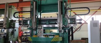
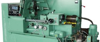
General form
In this picture you can admire the general view of the screw-cutting lathe. The components and various devices discussed earlier are immediately visible.
The weight is more than two tons, and the engine power reaches ten kW. The next picture shows a more detailed drawing, which shows the nodes and their location.
Drawing
This is a general design drawing. It shows all the main components. They will be reviewed one by one very soon. In the upper left corner is the front headstock, in the lower left corner is the gearbox and engine unit.
To the right of the front headstock the chuck is visible, and to the right of the chuck there is a guard, a carriage. Under the numbers 12, 13 in the middle there is a switch, an apron.
Top right - caliper, handle release mechanism, cooling, tailstock, electrical equipment, bed.
Location of controls
The picture shows all the controls and their locations. There are twenty-two organs in total. From the simplest to the very difficult to manage and study.
They control all the mechanisms, thanks to them the unit works and performs tasks. They will not be considered, however, in order to work with the machine you need to know them to avoid accidents.
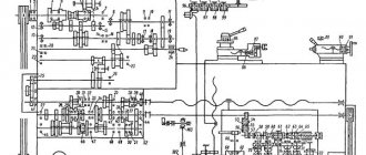
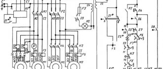
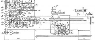
Kinematic diagram
The photo shows a kinematic diagram, that is, a conventional image of the unit, which shows the connection between the elements of the mechanism that transmit movement. The diagram helps to better understand the design of the structure, repair it correctly, and make correct calculations.
Each element in the diagram has its own designation. The symbols must be learned in order to understand the diagram. The shaft is indicated by a straight line, the lead screws by a wavy line, and so on.
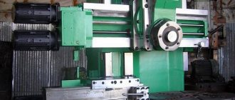
Headstock
Previously, the rear one was considered, but there is also a spindle one. It is best seen in the picture above. The design is a unit of grinding machines.
It consists of a supporting spindle, which imparts rotational motion to the grinding wheel. The purpose of the mechanism is to place the spindle and its drive mechanisms.
Apron design of a screw-cutting lathe
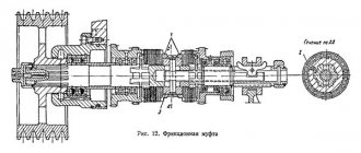
The feed through the lead screw is turned on by closing the uterine nut (Fig. I, 15). It consists of two half-nuts 1 and 2, which can move along guides made in the apron. Using handle 4 on the front side of the apron, the half-nuts can be brought closer together, locking them on the lead screw, or released; they are moved by a disk 5 with shaped grooves into which pins 3 pressed into half-nuts enter.
The movement from the running roller is transmitted through a gear z = 27 sliding along it together with the apron (see Fig. 1, 6) to the worm gear of the apron. From the worm wheel shaft, rotation is transmitted depending on which of the gear couplings M6, M7, M8 or M9 is engaged - either to the rack gear g = 10 - to obtain longitudinal feed, or to the gear g = 20, sitting on the feed screw XXI transverse slide - to obtain mechanical cross feed. Turning on all these couplings on the machine mod. 1K62 is produced with one handle (Fig. I, 16), and the direction of activation coincides with the direction of feed of the cutter. The longitudinal movement of the caliper is carried out manually using the handwheel on shaft XXII when the mechanical feed switch handle is set to the middle position. The apron has a device that prevents the feed from being switched on simultaneously along the lead screw and the lead roller (blocking), since such switching on would lead to breakdown.
Screw-cutting lathe apron
To protect the feed chain from overloads, as well as for working against stops (see page 46), a safety gear coupling MP is installed on the worm axis (see Fig. 1.6), the spring of which is adjusted to transmit a certain torque. If the torque exceeds the permissible value, the clutch will begin to click.
Reducing the time required to perform auxiliary movements is an important reserve for increasing the productivity of machine tools; Therefore, most modern machines have mechanisms that provide fast (“accelerated”) idle movements of the tool. In the 1K62 machine, for this purpose, a separate electric motor (Fig. I, 17) with a power of 1 kW, connected by a V-belt drive to the running roller, is installed at the right end of the frame. The one-way overrunning clutch Mo in the feed box allows rotation of the drive shaft to be transmitted both from the feed box and from the auxiliary engine.
The overrunning clutch (Fig. I, 18) has an outer ring 2, a shaped disk 1, rollers 3 and springs 4, pressing rollers. Such a coupling can transmit torque when the rollers jam in only one direction.
In the feed box of the machine, the outer ring of the overrunning clutch is rigidly connected to the gear block z - 56 (see Fig. 1.6), and the inner disk is connected to the running roller XVI. When the auxiliary motor is not turned on, movement is transmitted to the drive shaft from the feed box; When this engine is turned on, the clutch disc rotates in the same direction as the outer ring, but at a higher speed, and this causes the overrunning clutch to slip. After stopping the engine, the working feed chain is automatically restored. The rapid movement motor is turned on by button K (see Fig. I, 16) on the handle for turning on the automatic feeds. The fast movement mechanism provides a speed of longitudinal movement of the caliper of 3.4 m/min and transverse movement of 1.7 m/min. In heavy screw-cutting lathes with several supports, rapid longitudinal and transverse movements are carried out by separate electric motors installed on each support.
Photo of the apron of a screw-cutting lathe
Screw-cutting lathe apron
Rules of operation and care
There are rules for caring for the unit so that it does not break down and is always ready for use. The equipment must be regularly inspected and checked for damage.
Engine operation is determined by sound. After starting, listen. If there are no extraneous sounds, oil is supplied, then the engine is working. If there are extraneous sounds, you need to disassemble the mechanism and find out the reason.
Care must be taken to ensure that the safety shield is holding the workpiece. Even if there is a minor malfunction, you must stop working and take the parts for repair.
From time to time, clean pipes and equipment, change cutters so that the load on the engine is less.