History of the creation of a lathe [1]
The first lathes , which appeared in Europe in the 15th - 17th centuries, were wooden and manually driven. The machines were used mainly for making furniture and artistic woodwork. Very rarely, machines were used to turn iron shafts into regular shapes.
Iron lathes for metal , for the manufacture of shafts, axles, and screws for industry, appeared at the end of the 17th century, but they had not yet become widespread, since the most important parts of machines, including steam ones, were made by mechanics by hand. The need for machine production of metal machine parts, associated with a widespread transition to machine production in all industries, fully manifested itself only at the end of the 18th - first quarter of the 19th century. and served as an impetus for the improvement of metal-cutting lathes.
For the first time, the experience of many generations of turners was summarized by the French scientist Charles Plumier (French Charles Plumier; 1646 - 1704), writing a work published in Lyon in 1701. By order of Peter I, the book was translated into Russian in 1716 and was used to improve Russian-made lathes.
Lathes by that time already had the main components of a lathe: a bed, a headstock, a tailstock, but they were still driven manually and did not have a mechanized support . The cutter was in the hands of the turner, so there was no need to talk about accuracy. Machines were used mainly for the production of artistic products of complex shapes.
In Russia, the most famous designer of lathes was Andrei Konstantinovich Nartov (1693 - 1756). Nartov carried out the orders of Peter I, designing machines for figure turning. After the death of Peter I, Nartov worked in industry, collaborating with the Academy of Sciences. Nartov was one of the first machine tool builders to introduce a mechanized support and replaceable gears (1738) into the design of a lathe for cutting threads on screws.
In the West, the first inventor of a powered caliper is considered to be the English mechanic Henry Maudslay (1771 - 1831). Maudsley created the first design of a powered caliper in 1794. In 1798, he significantly improved the design of the support, which made it possible to create a version of the universal screw-cutting lathe. In 1800, Maudsley created a third version of the machine with a powered slide.
The next stage is the automation of lathes. Here the palm belonged to the Americans. In the second half of the 19th century. elements were introduced that ensure complete mechanization of processing - an automatic feed unit in both coordinates, a perfect system for fastening the cutter and the part. Cutting and feed modes changed quickly and without significant effort. The lathes had elements of automation - automatic stop of the machine when a certain size was reached, a system for automatically controlling the speed of frontal turning, etc. However, the main achievement of the American machine tool industry was not the development of the traditional lathe, but the creation of its modification - the turret lathe . In connection with the need to manufacture new small arms (revolvers), S. Fitch in 1845 developed and built a revolver machine with eight cutting tools in the turret head. The speed of tool change dramatically increased the productivity of the machine in the production of serial products. This was a serious step towards the creation of automatic machines.
Thus, after the invention of the mechanized support, lathes at the beginning of the 19th century had all the main components that modern screw-cutting lathes have: a bed, headstock and tailstock, and a support that allows them to perform many operations with high precision.
When did the first CNC machine appear?
The first CNC (Numerical Control, NC) machine was invented by the son of the owner of Parsons Inc, John Parsons.
The first CNC (Numerical Control, NC) machine was invented by the son of the owner of Parsons Inc, John Parsons, who worked in the engineering department of the company owned by his father. This company specialized in the production of propellers, blades and related parts for helicopters.
Persons Jr. was the first to patent the idea of using a machine that processed materials for propellers and other parts using a program that was executed by reading the necessary information from punched cards.
Parsons and his first CNC machine
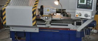
The design of a normal (universal) lathe and its main components [2]
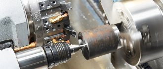
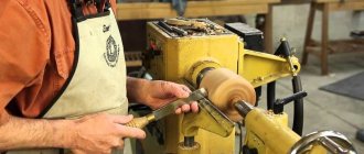
The operation of a lathe is to cut a layer of metal from a rotating workpiece using a cutter that is hardened, tempered and shaped to the proper shape.
A lathe or self-sharpening machine, as it is usually called in workshops, has an automatic feed and is mostly equipped with a lead screw for cutting threads. These machines are characterized by the following two main dimensions: the height of the centers, which is obviously equal to half the largest diameter that can be turned on a given machine, and the length between centers, which is equal to the longest length of the product that can be mounted and processed on a given machine. Both of these values are indicated in millimeters. The most common are small machines - the height of the centers is up to 200-250 mm and the length between the centers is up to 1500-2000 mm. Large lathes, built with a center height of up to 800 mm and a length between centers of up to 50 meters, are much less common. Such machines, however, are absolutely necessary for the manufacture of, for example, heavy implements, large pumps, engines, large shafts, etc.
The main operations of a lathe are: round or cylindrical turning, cone turning, cylinder or cone boring, face turning (i.e. turning in a direction perpendicular to the axis of the product) and thread cutting. For special work, it has special devices, such as, for example, a device for rear sharpening (removing the backs), for milling, for grinding, for conical turning (“copier”), etc.
The most prominent place among special lathes is occupied by a turret lathe, adapted for mass production of products. It takes a lot of experience and skill to prepare and install several different cutting tools in the turret and stops to limit the travel of the caliper. But when this is done, when, as they say, the machine is set up, then no qualifications are required to work on it. Working on a lathe, performing a variety of jobs, is much more interesting, and requires higher qualifications than working on a turret lathe.
In a metal lathe, the workpiece rotates about a horizontal axis parallel to the longitudinal axis of the machine, and at the same time is processed by a cutter that slowly moves (feeds) in a direction exactly or approximately parallel to the axis of the product (longitudinal feed) or perpendicular to it (transverse feed ). Both movements of the cutter - longitudinal and transverse - can be performed either manually or automatically (mechanically) - or, as they say, “self-propelled” - from the machine drive.
When the feed is made in a direction exactly parallel to the axis of the product, the surface of the product is turned in the form of a circular cylinder (cylindrical, round turning). If the cutter moves at a slight angle to the direction of the axis of the object, then the surface of the object is turned to a cone (conical turning, cone turning). As this angle increases, the angle at the apex of the cone that forms the workpiece increases accordingly; in other words, the surface of the part will become more and more different from the cylindrical one. Finally, when the cutter moves perpendicular to the axis of the product, i.e. with a transverse feed, turning is called transverse, frontal or end-to-end. Machining the inner surface of a product on a lathe is called boring.
Turn of the century lathe parts
- A. Bed;
- B. Headstock;
- C. 3rd headstock;
- D. Caliper;
- D—1. Sled
- D—2. Front board (apron, apron) of the caliper;
- E. Feed mechanism and screw-cutting mechanism;
- F. Lathe accessories.
- Guides (prismatic);
- Main (working) spindle. Made from crucible steel and ground to precise size. The axis of rotation of the spindle determines the line of centers of the lathe;
- Rotating center. Rotates with the spindle and forms a stop for the workpiece;
- Drive cartridge for transmitting rotation to the product;
- Pull handle. When turning toward oneself, the overdrive engages, and when turning away from oneself, it disengages it;
- The locking pin (bolt) extends when the switch is turned on, and moves in when it is turned on;
- Two-speed gearbox handle. When turning to the right - the speed is higher, when turning to the left - the speed is lower;
- Handwheel on the motor shaft to rotate the spindle manually;
- Tailstock clamping bolt;
- Fixed (posterior) center. Smoothly turned and hardened; does not rotate and provides support for the workpiece;
- Tailstock spindle;
- Reservoir for oil, which serves to lubricate the fixed center;
- Tailstock spindle handle, used to secure it in place;
- Tailstock spindle handwheel, for rotating the tailstock spindle screw, transmitting movement to the spindle;
- Screw for installing the tailstock on the slide;
- Tailstock slide. Allows slight lateral movement along the main tailstock board. Installed using a screw (15);
- Main board (base) of the tailstock;
- Cross slides. Move in a direction perpendicular to the line of machine centers. They are moved manually or self-propelled (transverse feed);
- Cross feed handle (screw) with a graduated sleeve. Each division usually corresponds to a movement of 0.025 mm or 0.001″ of the cross slide;
- Tool holder (“Soldier”);
- Ring and ball lining of the tool holder;
- Rotating part of the caliper. The figure shows a cross slide with a main board divided into degrees, which can be rotated about a vertical axis to any position relative to the cross slide;
- Upper slide screw handle;
- A clamping bolt for securing the caliper to the bed guides. Used for frontal turning of large diameter products;
- Handwheel for manual longitudinal feed of the caliper;
- Button to turn on the feed gear;
- Longitudinal feed button;
- Cross feed button;
- Master nut handle;
- Handwheel for starting and stopping the electric motor;
- Bit handle for changing the direction of self-propelled guns, as well as rotation. In the middle position, its supply is turned off;
- Drive feed pulley;
- Driven feed pulley;
- Transmission gear, freely sitting on the axis;
- Intermediate (parasitic) gear;
- Gear jammed on the lead screw;
- Speed box for changing the feed (at 3 speeds);
- Handle for changing feed speeds (its three positions correspond to three different speeds of rotation of the lead roller or lead screw);
- Gear drive to the drive shaft;
- Cam clutch for transmitting motion to the lead screw;
- Clutch handle for transmitting motion to a lead screw or shaft. When turned to the right, the clutch (40) engages and drives the lead screw; when turning left through the bust (39), it turns on the roller. In the middle position, neither the lead screw nor the lead shaft rotates;
- Running roller;
- Feed mechanism rack;
- Lead screw for feeding the caliper only when cutting screw threads;
- Adjustable stop for adjusting the length of the longitudinal self-propelled vehicle;
- Stop used when cutting threads;
- Faceplate;
- Fixed rest;
- Movable steady rest;
- Replaceable gears;
- Lathe chuck (4-jaw);
- Drill chuck.
What a beginner turner should know.
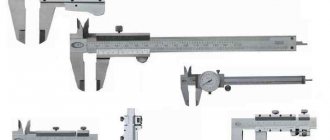
To start working on a lathe, it is not enough to be able to start and stop it. A novice turner must first become thoroughly familiar with the cutters - study their shape, learn how to sharpen them and how to secure them in a support so that they cut metal. He must be able to quickly and accurately read divisions on a scale, must know how to measure a product with calipers in order to obtain the size with an accuracy of 0.1 mm. He should as soon as possible learn the names of the individual parts of the machine and learn their meaning. He should be fairly well aware of the values of cutting speeds and feeds for different processing cases. He must be able to properly lubricate the machine wherever required. After all this has been learned, you can start working on the machine.
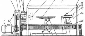
In fig. 42 shows a normal screw-cutting lathe. Its individual parts are designated by numbers and their names are given in the table on pp. 103-104. A lathe operator must know the name of each part of the lathe and its purpose.
bed
The cast iron bed of the machine is made quite high and wide and reinforced inside with transverse ribs; this is done in order to increase the rigidity, stability and strength of the machine, which is especially important when removing large chips. The bed guides in modern small and medium-sized machines are always made prismatic (that is, in the form of a triangle with a truncated corner facing upward), threaded or milled and then scraped. External guides represent “rails” exactly parallel to the axis of the machine along which the support moves. The headstock is fixedly mounted on the inner guides, which are just as precisely machined as the outer ones; the tailstock can move along them and be installed in any position. The side edges of the guides usually make an angle of about 90°. Their upper edge is slightly rounded to prevent chipping.
Headstock
The headstock consists of: cast iron body; spindle; a mechanism for communicating different rotation speeds to the spindle (“working speeds”); a mechanism for transmitting motion from the spindle to the feed roller and to the lead screw of the screw-cutting mechanism.
The lathe spindle rotates in two bearings located at either end of the headstock. These bearings must be extremely precisely bored and ground in order to ensure that the spindle's axis of rotation is exactly parallel to the bed guides. The spindle is usually made hollow, with a through hole, bored to the front end of the spindle into a cone, into which a movable (“front”) center is inserted. The supporting surfaces of the headstock bearings, the front end of the spindle, equipped with an external thread, and the conical hole for the center are machined with particularly high precision, and we must try to maintain this accuracy. The spindle of the machine, rotating, determines the speed of rotation of the product, as, for example, in a lathe, or a cutting tool, as in a drilling machine. It must be precisely calibrated and absolutely correctly installed, since if there is the slightest violation of the accuracy of its installation (i.e., if its axis is not parallel to the frame guides or the bearings are incorrectly adjusted and the spindle has “play” along the axis), it is impossible to obtain a precisely machined product.
Tailstock
The tailstock (Fig. 43) consists of the following parts: spindle; a housing in which a cavity for the spindle is drilled; main board with internal guides; a screw with a handwheel attached to its outer end to move the spindle; spindle clamping device; clamping bolts to secure the tailstock to the bed.
The main purpose of the tailstock is to serve as a support for such products that are turned on centers. To make it possible to install products of different lengths between the centers of the machine, the tailstock is made movable along the internal guides of the frame, and it can be fixedly fixed in any position. In addition, the tailstock spindle (11), into which the fixed (rear) center (10) is inserted, can receive longitudinal movement by rotating the handwheel (14), which imparts movement to the screw (S).
The tailstock spindle is carefully fitted to the housing sleeve enclosing it and normally (that is, with cylindrical turning) its axis lies on the same straight line with the axis of the working spindle. The tailstock spindle cannot move in the vertical direction. In the transverse direction 1) the entire tailstock body, together with the spindle, can be shifted: when the set screws A are rotated (the second similar screw is located on the other side of the tailstock), the headstock moves across the bed, towards or away from the turner. The spindle is kept from rotating in the tailstock bushing by a key running along the spindle, approximately 2/3 of its length. Thanks to this, it can slide freely along the sleeve, but cannot rotate inside it. The spindle is made hollow. From the front end it is bored into a cone, which carries a fixed center.
A bronze nut N is inserted into its other end, bored cylindrically. When the handwheel (14) rotates, the screw S rotates freely in the cover C of the headstock housing. The propeller is held against translational motion on one side by a handwheel and on the other by a shoulder. Thus, when the screw rotates in nut N, it will feed the spindle forward or backward, depending on the direction of rotation of the handwheel.
In order to remove the center from the tailstock spindle, you need to rotate the handwheel so that the spindle goes back until the end of the screw rests on the center. As the handwheel rotates further, the screw will push the center out of the spindle.
If the spindle has come out of the housing so much that it has jumped off the screw, then before you start tightening the spindle with the screw in the opposite direction, you need to make sure that the keyway is exactly against the key.
Do not push the spindle too far back, otherwise it will be pressed against the shoulder and may become pinched.
Caliper
The support consists of a longitudinal slide and a front board (apron). The longitudinal slide moves along the outer guides of the frame; a prismatic wedge placed at the back protects them from tipping over. They are shaped like the letter H, the long sides of which slide along the guides, so that the slide is thrown over the bed like a bridge. The longitudinal slide carries a transverse slide, a turntable and a tool holder (“soldier”). The support serves mainly to install the cutter. It can be given movement—feed—either manually or by means of a self-propelled mechanism along the outer guides of the frame (the so-called longitudinal feed). The upper part of the main slide is planed in the form of guides along which the transverse slide can slide, moving the upper part of the support along with the cutter in a direction perpendicular to the longitudinal feed. This feed is called cross feed and can be done either manually or self-propelled.
The front board (apron, apron) of the caliper carries gears and couplings on the inside, with the help of which the movement of the running roller is transmitted to the caliper, as well as a sliding uterine (half) nut, which locks onto the lead screw when cutting a screw thread.
The directions of all movements are referred here and everywhere else to the line of centers of the lathe.
Feed mechanism
To transmit movement from the spindle to the running roller of the machine, running along the entire bed, two or more gears (i.e., interlocking gears) are used, one of which is located in the headstock (snaffle), and the other on the left end of the bed. From the rotating roller, the movement is transmitted through a series of gears located on the inside of the apron to the caliper, giving it either longitudinal self-propelled (longitudinal slides move along the bed guides) or transverse self-propelled (transverse slides move along the guides of the longitudinal slides across the bed). The feed gears located on the front plate of the caliper are switched on and off by means of friction clutches, which are controlled by buttons located on the outside of the apron. By simply turning the corresponding button, the turner starts or stops the longitudinal and transverse self-propelled guns.
Screw-cutting mechanism
The self-sharpening screw-cutting mechanism contains gears necessary to transmit movement from the spindle to the lead screw. Usually these are the same gears that serve to transmit rotation to the drive shaft. The lead screw is located along the frame, usually above the lead roller. This screw is made of a fairly large diameter and is equipped with a large thread ¹), which must be cut with high precision.
To transfer movement from the lead screw to the caliper, you need to close the halves of the master nut, which are fixed in the caliper apron, onto the screw.
The lead screw should not be used for self-propelled feeding in normal turning operations, and the lead screw should not be used for thread cutting.
A detailed description of the feed mechanism and screw cutting mechanism is given below.
Spindle rotation speeds. Changing the spindle speed
Since the machine has to turn products of different diameters, the spindle must be able to rotate at different speeds so that the proper cutting speed can be obtained for any diameter - from the smallest to the largest, which can be processed on the machine with a certain center height.
In machines with direct drive from an electric motor, changing the spindle speed is achieved partly by changing the speed of the motor itself, and partly using gears in the headstock. However, in most cases, self-sharpening machines are belt driven, and operating speeds depend on the size of the pulleys and headstock gears. Movement is transmitted to such machines in the following way: from any engine or electric motor, rotation is transmitted by a belt to the main transmission shaft, from it to the counter drive, and from a stepped pulley on the latter to the stepped pulley located on the front headstock of the machine. “Stepped” is a pulley that has several “steps”, i.e. pulleys of different diameters connected together.
Gear busting
To increase the number of operating speeds, spindles, lathes (and many other types of machines) are equipped with gearing, which is usually called simply gearing. The purpose of the overdrive is to reduce the spindle speed compared to the speed of the stepped pulley. This decrease in speed is accompanied by a simultaneous increase in the strength of the machine. Some self-sharpening machines have two or more busts.
Gears B and C of the search (Fig. 47) are jammed on a long sleeve (3), rotating freely on the roller E, the ends of which lie in bearings located in the bosses of the headstock behind the spindle.
As can be seen from the drawing, the ends of this roller - axles or spikes - are eccentric, i.e. their axis does not coincide with the axis of the part on which the bushing sits.
Thanks to this device, the rear bulkhead can be engaged or disengaged from gears A and D: this is achieved by turning the roller E with handle I.
In fig. 47-a the dotted line shows the position of gear B when the search is turned off.
Spindle speeds with enumeration enabled
In fig. 47-6 the overdrive is engaged with the spindle gears and the clutch bolt is disengaged. Gear A is fixedly connected to the stepped pulley, and the transmission of motion occurs as follows: from the stepped pulley and gear A to gear B, bushing and gear C of the bust; from C - spindle gear D, immovably wedged by means of a key on the spindle. If the diameter of B is three times the diameter of gear A, then its speed will be three times less. Since gears B and C are both jammed on a common bushing, they will rotate at the same number of revolutions. If, further, gear D is three times larger than C, then it will rotate at a speed three times less than C. Therefore, in general, gear D will rotate at a speed of 1/3 • 1/3, i.e. 1/9 speed A; in other words, for the given ratios of gear diameters, the number of revolutions D, and at the same time the spindle, is nine times less than the number of revolutions A, i.e. step pulley. The total number of speeds with enumeration is equal, of course, to the number of pulley stages. Thus, a machine with a three-stage pulley and overdrive has only six speeds: three without overdrive and three with overdrive.
Modern CNC machines
Nowadays, PU equipment is a part without which it is impossible to imagine any production facility producing high-quality products.
The main advantage of devices with CNC systems is not only that it becomes possible to process parts and workpieces of complex shapes, but also that the entire production process becomes more and more automated every day.
Currently, companies use equipment produced in different periods of time. For this reason, numerical control systems have significant differences both in design and in the method of programming and further work with them. Basically, if they have the financial opportunity, companies try to replace outdated CNC systems with new, modern ones, so even machines of the same model, released at the same time, can differ significantly in the software and electronic parts associated with numerical control.
Feed rates and their control
The longitudinal feed of a gravity grinder is the movement of the entire support along the guides of the machine, i.e. parallel to the axis of rotation of the spindle or parallel to the line of machine centers. Cross feed is the movement of the cross slide perpendicular to the center line of the machine.
Each of these feeds can be done in both directions, either by hand (manual feed) or automatically (self-propelled). The amount of manual feed depends entirely on the turner: it can be fast or slow and the spindle can work or remain stationary at this time. Self-propelled feed, on the contrary, is completely automatic and consists in the fact that for each revolution of the spindle there is a certain length of movement of the caliper. When feeding by self-propelled motion, the movement is transmitted from the rotating spindle of the machine through a series of gear wheels to the roller, and from it through a system of gears located in the apron of the caliper, either to the lower slide of the caliper, or to the cross-feed screw, depending on the direction in which the cutter should move during operation .
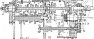
Transfer from spindle to feed mechanism
Fig. 50 shows a diagram of the transmission of motion from the spindle to the lead shaft and the screw. Gear Sp is wedged on the spindle (1) and transmits motion through gear R1 to gear FS, wedged on the intermediate shaft (2). Gears R1, R2 and FS form the reversing mechanism, described in detail in the next paragraph. This mechanism is usually placed inside the headstock housing of the machine.
The other gear St of the intermediate roller (2) is replaceable, i.e. it can be removed from the roller and replaced with another one of larger or smaller diameter. Since it is keyed onto the shaft (2), it rotates simultaneously with FS. Through the intermediate gear (parasite) J, the movement is transmitted further: to the replaceable gear Sc, wedged on the lower roller (3) of the feed box, at the same time to gear E, and from it to gear B, sitting motionless on the upper roller (4) of the feed box. When the claw clutch C - H is disengaged (as shown in the diagram), the movement is transmitted further from the roller (4) to the running roller (5) through a pair of gears G1, G2. When the left half of the C clutch is shifted to the right, so that it is in engagement with the other half of the coupling H, then the lead screw (6) rotates, since H is fixedly fixed to it. The roller does not rotate, since G1 is no longer engaged with G2.
According to the described scheme, gears are arranged in most existing lathes, and all the differences come down to design details.
Reversing mechanism (snaffle)
The axes of the gears R1 and R2 of the reversing mechanism, the so-called snaffle, are mounted in a bracket that swings on the trunnion of the intermediate roller (2). By means of the reversible handle (marked 31 in Fig. 15), the bracket can be installed in any of the three positions shown in Fig. 51. The reversing gears are intermediate between the spindle gear Sp and the gear FS (see Fig. 50) and are fixed in the bracket in such a way that either only one gear R1 or both R2 and R1 can be engaged, or both can be disengaged. In other words, in the first position of the handle, the intermediate roller (2) rotates to the right, in the second - to the left, in the third - it is stationary. The snaffle therefore serves to change the direction of rotation of the lead shaft or lead screw.
Idle gear. Guitar
The idler gear, designated J in FIG. 50, rotates on a short roller or axle, which is fixed in a rather long slot in a cast iron board (1) of a special shape (Fig. 52), the so-called guitar. The guitar can rotate around the axis of the intermediate roller. Thanks to this device, for any (within certain limits) diameters of the replaceable gears St and Sc, the intermediate gear J can be installed so that it is in mesh simultaneously with both of these gears.
To change gears, first of all, release nuts A and B (Fig. 52), then the guitar clamp bolt C and, finally, nut D, while supporting the intermediate gear with your hand so that it does not immediately fall down along the slot of the guitar. Once one or both of the replacement gears have been replaced by others, lift the idler gear so that it meshes with the top gear, tighten nut D, rotate the guitar so that the idler gear engages with the lower replacement gear, and finally tighten the securing bolt C.
To ensure that the required gap remains between the gear teeth, before tightening bolt C, narrow strips of paper are placed between the meshed teeth of adjacent gears.
Feed speed box (Norton box)
Instead of the mechanism just described, which requires a change of suitably selected gears to change the feed speed, many modern machines are equipped with the so-called. feed speed box or Norton box. This box allows you to change the feed, which is especially important in the case of cutting screws, without replacing gears in the feed mechanism, simply by moving one or more handles from one position to another. In fig. 53 shows a diagram of the feed speed mechanism of the machine from the Hendy plant. A keyway is milled along the lead screw, thanks to which it produces feed both when cutting screws and during simple turning. Consequently, there is no need for a running roller. By turning two handles, 36 different feed speeds are obtained. One handle moves gear B, sitting on the long key of roller M, along this roller, so that gear B is opposite one of the gears of the feed speed box A (separately shown in Fig. 53 on the right), jammed on the lead screw. At the same time the handle raises an idler gear (not shown in the diagram), which is in constant mesh with B, and which, when lifted into such a position as to mesh with one of the gears of box A, transmits the motion from B to that latter gear. In the diagram, gear B is shown in such a position that the transmission of motion would occur from B through the intermediate gear to the Norton gearbox, which has 70 teeth.
All gears of the feed speed box (there are only twelve of them in the drawing) are jammed, as already mentioned, on the lead screw. The described device makes it possible to obtain twelve different feed rates at a given roller speed M, since there are twelve gears of different diameters in box A. Roller M can be given three different speeds by means of a second handle, which moves the system of gear wheels L, K and H into one of the three positions shown in the drawing. Consequently, such a device gives 3 X 12 for each speed of the working spindle, i.e. 36 different feed rates, and when using a uterine nut - 36 screw threads with a different number of threads per 1″.