People have long realized the possibility of obtaining smooth and even and even standard surfaces by turning the workpiece while rotating it. The appearance of the first lathe dates back to 650 BC.
Its design was ridiculously simple: 2 coaxial centers, between which the workpiece was inserted. One person rotated this workpiece, and another, using a cutter made of a harder material, turned it.
The parts were mainly made of bone or wood, since there was neither sufficient power for processing metal nor materials of sufficient hardness (so that a chisel could be made). Time passed, technology developed, and so gradually, the machines reached their modern appearance and capabilities.
Specifications
Table 9.
| Maximum workpiece diameter | mm | Ø480 |
| Max turning diameter | mm | Ø280 |
| Maximum turning length | mm | 510 |
| Max. diameter of the processed bar | mm | Ø71 |
| Spindle speed | rpm | 4500 |
| Spindle connecting end | A.S.A. | A2-6 |
| Diameter of through hole in spindle | mm | Ø82 |
| Chuck size | mm | Ø200 (8´´) |
| X-axis movement | mm | 165 |
| Z axis movement | mm | 530 |
| X-axis rapid motion | m/min | 30 |
| Z axis rapid movement | m/min | 30 |
| Tool store | ||
| Number of installable tool positions | PC | 10 |
| External Tool Dimensions | mm | 20×20 |
| Tool dimensions for internal machining | mm | Ø32 |
| Tailstock | ||
| Tailstock diameter | mm | Ø65 |
| Tailstock quill cone | MK 4 | |
| Tailstock movement | mm | 470 |
| Tailstock movement type | manual with programmable quill | |
| Power characteristics | ||
| Spindle motor power | kW | 11/15 |
| X-axis servo motor power | kW | 1.8 |
| Z axis servo motor power | kW | 1.8 |
| Total power consumption | kW | 21 |
| Dimensions | ||
| Length × width | mm | 2130×1670 |
| Height | mm | 1570 |
| Weight | kg | 3200 |
Types of machines
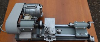
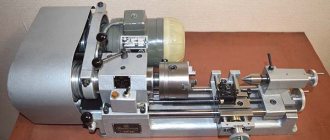
Tabletop, they are also mini-lathes for metal.
Please note that some models of this type are produced without a tailstock, which can significantly complicate operation. In general, these are machines of the simplest design: small dimensions, light weight, fairly light and unstable frame. School machines, larger than previous ones. They have a two-speed gearbox and reverse.
Screw-cutting lathes. They are more suitable for the garage than for the home; they have a durable frame, thanks to which there are almost no unnecessary vibrations during operation.
The spindle in such machines rotates almost without runout. They have only two disadvantages: dimensions and high price.
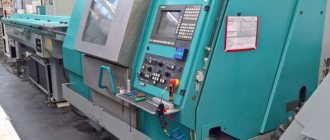
CNC machines, depending on the characteristics of the machine, are selected according to technological capabilities:
1.Powerful drive of the main movement. DC motors are used, allowing for stepless control of the spindle speed, or three-phase AC motors with a large number of control stages (chuck-center lathe 16K20F3S5).
The spindle speed control limits change up to 200 times (single-stage rotary lathe 1516F2).
2. Stepless drive of the feed movement with very wide limits of control of the feed amount. For the 16K20F3S5 machine, the feed rate varies from 1 to 1200 mm/min, i.e. 1200 times. This makes it possible for each specific case to select the feed that is optimal for processing conditions.
3. The machines have two coordinates with independent control for each of them. This makes it possible to implement very complex trajectories of movement of working bodies, unattainable for non-numerical control systems (vertical milling console 6R13FZ machine).
4. The lathe model DS2/NS has a speed of caliper installation movements of 4.8 m/min. This allows you to minimize the time of idle movements.
5. All of the listed machines have high manufacturing precision and increased rigidity compared to conventional machines for similar purposes. This allows for high processing accuracy.
6. The machines are equipped with developed tool systems with the number of tools 6-8-12 (vertical drilling machine 2Р135Ф2, lathe model DS2/NS, CNC turning center DMC DL series 8TH,).
7. The machines (lathe model DS2/NS, CNC turning center DMC DL series 8TH) are equipped with mechanisms for automatic chip removal.
8. CNC systems are equipped with correctors, which are located on the console and are structurally designed in the form of a set of decade switches. Using correctors, it is possible to compensate for systematic processing errors, inaccurate settings of cutting tools, non-rigidity of the AIDS system, temperature deformations, and dimensional wear of the tool.
1.5. Kinematic and power characteristics
The main kinematic characteristics of the cutting process are the cutting speed V and the feed S. The cutting speed for machines with a main rotational movement is ensured by the rotation of the spindle and is regulated by its rotation frequency; for machines with a main translational motion - the speed of the table, which is measured by the number of double strokes per minute.
The feed is provided by the feed drive. Feed per revolution is measured in millimeters per revolution of the spindle (revolutionary feed), in millimeters per minute (minute feed), in millimeters per double stroke (for machines with a main translational motion). In addition to working movements in the machine, there are auxiliary movements that are not related to the cutting process, but are necessary for the complete implementation of the cycle.
Power parameters of the cutting process - cutting forces and cutting power depend on the width of the cut layer and are provided by the drives and mechanisms of the machine.
The technical characteristics of the machine include the following kinematic and power indicators:
- range of spindle rotation speeds and feeds (for a step drive - ranges of frequencies or numbers of double strokes per minute);
- the highest rotation speed of the grinding wheel (for grinding machines);
- speed of auxiliary movements;
- power of the electric motor of the main movement drive or the maximum torque on the spindle.
Exploitation
A slight increase in the gaps between mating parts, leading to a decrease in processing accuracy, is eliminated by adjustment. Significant wear requires repair or replacement of parts. To reduce wear and prevent mechanical breakdowns during operation, it is necessary to follow the rules of equipment care.
Main movement
Since the cutting process occurs due to the rotational energy of the blank, it is usually called the main movement of the turning group equipment. The main movement drive consists of a single-speed three-phase asynchronous electric motor equipped with a manual gearbox.
Feed movement
The translational movement of the tool, ensuring contact of the cutter with the surface of the workpiece at the desired point, is called the feed movement. Its drive switches depending on the task being performed and can be manual or mechanical due to the power of the main drive.
Feeds and main movement are the main movements of the turning group equipment.
Longitudinal and transverse feed of the caliper
To move the support along and across the axis of rotation of the blank, longitudinal and transverse slides are used, respectively. Each of them is equipped with its own guides and screw drive. Transverse feed allows you to change the depth of cut and, in combination with longitudinal feed, form the required surface of the part.
Multi-start thread cutting
The selection of replacement gears is done in the same way as for cutting a single-start thread. With the difference that to determine the thread progress, its pitch must be multiplied by the number of starts. If the drive of the upper slide of the caliper is not too worn, division into approaches can be done by setting the latter parallel to the axis of rotation of the part. After cutting the groove in the first pass, the cutter, removed from the metal, is returned to its beginning. Then the cutter is retracted to a distance equal to the thread pitch from the first start. After which they begin to cut the second one.
Processing of shaped surfaces
The production of products with complex surfaces is possible in several ways:
- Using conventional cutters using alternating longitudinal and transverse manual feed. The method has low accuracy and productivity. Requires well-developed execution technique.
- Special shaped cutters. The method is highly productive, but requires non-standard cutters.
- With ordinary cutters using copiers or circular feed devices. The method is highly productive, but requires manufacturing or equipment.
Purpose of lathe 16K20
The range of application of the equipment was and remains the turning of the internal and external surfaces of products having:
- rhonic;
- cylindrical;
- end;
- aason;
- complex structure.
Using the equipment, its operator can perform actions related to drilling holes, creating external and internal threads of all types, leveling the surface, as well as creating a corrugated structure.
The universal nature of the unit makes it possible to process workpieces and repair objects made by hot-rolled and cold-rolled methods. At the same time, the machine demonstrates unchanged properties in the form
- Efficiency.
- Safe operation.
- Processing precision.
- Easy care.
- Long service life.
- Stable and continuous operation.
The machine is the optimal choice when working with disks, various types of bushings, shafts and similar elements.
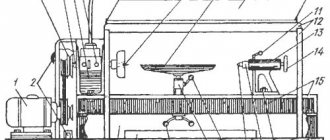
Features and modifications of the 16K20 lathe
The features of the equipment that brought it wide popularity throughout the USSR, as well as popularity in Eastern Europe, China and Switzerland include:
- rigid frame, which is installed on a monolithic stand. The bed is made in the form of a box, has polished grooves;
- workpieces and elements being processed are fixed in a chuck or in centers;
- the structure of the clamp guarantees reliable fastening of removable attachments;
- the base of the spindle is made of rolling bearings belonging to the precision group;
- a complex of protective and blocking devices is the key to safe operation;
- scale rulers equipped with sights make it easy to move the cutting and cross slides;
- the apron includes a mechanism for shutting off the caliper supply;
The first serial machine, whose production started in the 1970s, already had all the properties described above. Subsequently, it was produced in parallel in several versions, which will be discussed below. Foreign manufacturers also produced (and continue to produce) their analogues.
The role of the key processing tool was played by the hydrocopying mechanism. As a result, the processed workpiece could be used as a template. The machine was widely used in mechanical engineering, instrument-making enterprises, and repairs.
- Model 16K20G. The main difference between this unit is the recess in the frame. The scope of use of the machine remains all types of turning work.
- Model 16K20VF1. In her case, the company received high-precision equipment. The unit effectively copes with finishing work, cutting threads of all types, and processing geometric and rough surfaces. The equipment is universal in nature, it can be used for mass production, production of small batches, single copies and repairs.
- Model MK6056. An improved version of the 16K20 lathe. Together with the MK6057 and MK6058 models, it was produced in Moscow from the mid-80s until the bankruptcy of the enterprise.
- Model GS526U. Belarusian lathe, currently produced in the city of Gomel.
- Model Opti D420x1000. A German analogue of the 16K20 machine, which is produced in China.
- Model CA6140A. Direct Chinese version of the unit. Along with the models CA6140B, CA6240A, CA6240B, it is produced in the Middle Kingdom.
Read also: How to test the board for functionality with a multimeter
Along with the presented versions, there are numerous analogues of the machine. They are produced by companies from Russia, Eastern and Central Europe.