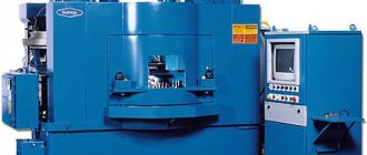
Purpose and scope of screw-cutting lathe
TB-01M is a machine model on which a variant from the 1E61M series is built. The equipment represents the class of light lathes. Serial production of the models began in 1965.
The device can be called universal, accuracy class – P. Suitable for the following operations:
- Finishing actions when turning various parts.
- Threading
There are several types of actions that are performed using machines:
- Drilling, processing of holes with various shapes. Including cylindrical, conical boring, countersinking, reaming, reaming.
- Treatment of external surfaces in the shape of a cone. In this case, the length of the conical part can be different. The same goes for the angle of inclination. Typically, special cutters, a tailstock body, and a copy-cone ruler are used during processing.
- Slotting cutters help make external grooves.
- To give the workpieces a certain shape, operations such as trimming, turning grooves and cutting are carried out.
- Boring of surfaces in the shape of a cylinder.
- Turning cylindrical surfaces that remain smooth.
Description of the lathe
About 70 years have passed since the production of 1a616 lathes ceased, but they are still in use in small workshops. This indicates a multiple safety margin that the designers laid down at the time.
The main purpose is cutting workpieces made of various metals and alloys, as well as non-metallic materials. It is technologically possible to perform the following work:
- straight and conical turning of external and internal cylindrical surfaces;
- direct and conical boring of external and internal cylindrical surfaces;
- end trimming;
- cutting several types of threads;
- turning to caliber after retrofitting.
Specifications
The 1E61MT has taken a leading position in its field, and for good reason. The installation is not suitable for mass stamping, but many other operations can be carried out on it.
The main parameters that deserve attention are:
- Diameter of the future thread.
- Selected speed modes.
- The length of the part, its compliance with the parameters of the equipment used.
If the dimensions mentioned above correspond to the operating conditions, then you can move on to the stage of setting up the machine itself.
Screw cutting equipment has the following parameters:
- 1650 kilograms is the total weight of the machine, if you do not take into account additional equipment.
- The minimum rotation speed is 35, the maximum can be 1600 rpm.
- Precise parameters associated with limb displacement. Along the longitudinal guide it is 0.2 millimeters, along the transverse guide it is 0.02 millimeters.
- Two cutting heads are installed on the front part. The second is mounted on the area at the back.
- The main holder has a total of up to 4 cutters.
Read also: What is hrc steel
- 32 millimeters is the diameter of the rods used.
- 170 millimeters is the permissible height for the central parts.
- At 125 W, a separate cooling pump motor operates. At 125 W - a motor connected to a lubrication mechanism.
- 4.5 kW is an indicator of the power of the main drive, due to which movement is carried out.
Additionally, the turning unit has a system that prevents damage associated with extreme loads. The mechanism is simply blocked if a dangerous situation arises. Model type 1E61PM works in approximately the same way.
Description of design
Here the user must take into account some nuances.
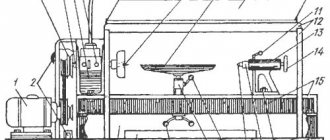
Location of main components
- The main unit is the bed.
Compared to other components, it has minimal weight. The part is mounted on a special platform using appropriate bolts. The bed has two guides. One of them is made in the shape of a “dovetail”, and the second looks like a prism. The support on the frame is held rigidly thanks to such shapes and wedges responsible for adjustment.
- The headstock is usually located on the left.
It is installed inside the grooves in such a way that the user can easily rotate the part a few degrees when the need arises. That is, the center moves relative to the axis without any problems. Then, when processing parts, it is easy to achieve a certain shape.
- The headstock houses the gearbox.
The control levers are located outside. A guitar of replacement gears is mounted in the front. Before cutting the thread, the gears are changed if necessary. The gearbox is the place where you can find the spindle assembly. The spindle itself rotates while maintaining speeds of up to 16-2000 rpm.
The main drive motor of the machine is located in a special cabinet on the left side. Forward and reverse rotation of the spindle is activated at any convenient moment.
- The tailstock is on the right side of the bed.
Various tools are inserted into this part, including the center and dies, taps, and drills.
The tailstock is securely fastened and moves easily along the surface of the bed. The quill stroke is 100 mm.
- An apron through which the shaft and screw pass.
- Caliper.
- Gearbox.
- Electrical cabinet.
- Lubricant and cooling fluid.
- Screen for added protection.
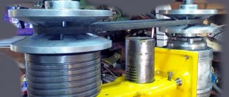
Headstock
The gearbox is involved in the process of transmitting the rotational motion of the spindle pulley. An individual electric motor also takes part here. Type “B” belts ensure the operation of the V-belt drive. The movement goes directly to the spindle through the bust, or bypassing it.
Read also: Galvanized sheet steel building facade
The design contains two rolling bearings. Due to this, the centering property is maintained, the wedge-shaped pulley of the wire does not lose its original position. The orientation is based on the central part of the spindle head. The tension of the V-belts does not have a negative effect on the structure. The spindle does not experience increased loads.
The spindle head has six speed stages in total. The block gears move along splines, which allows you to control the speed and select a specific option.
A separate pump, driven by an electric motor, is responsible for lubricating the headstock. Thanks to the presence of a lock, there is no chance that the system will start in the absence of the appropriate fluid.
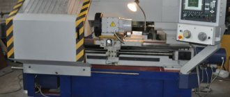
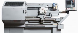
Screw-cutting lathe 1M61: characteristics, device, features
Screw-cutting lathe 1M61, developed in the 70s. last century by specialists from the Yerevan Machine Tool Plant, was intended to equip small enterprises that produce their products in small series and in single copies.
Screw-cutting lathe 1M61
How the machine model 1M61 works
The basis of the lathe model 1M61 is made up of ten elements, which include:
- supporting frame;
- gearbox;
- gear box;
- gearbox;
- apron;
- caliper;
- tailstock;
- electrical equipment system;
- a screen that performs a protective function;
- a system that provides cooling of the tool and processing area.
Main components of the machine
According to its technical characteristics, the machine model 1M61 belongs to the “N” accuracy category. The machine's electric motor can operate in reverse mode. The rotation speed of the equipment spindle is changed by means of a gearbox in which gears with different parameters are meshed.
On the 1M61 model lathe, working tools such as cutters, drills, reamers and taps can be used. This makes it possible to perform a whole range of technological operations: internal and external turning, drilling, reaming, threading, cutting, etc.
An apron is responsible for the transverse and longitudinal movements of the machine support, carried out using a lead screw and a lead roller, on the front of which there is a control flywheel. The 1M61 lead screw is used only when a thread cutting operation is performed, otherwise only the lead roller is used. The characteristics of the apron make it possible to block the combination of the longitudinal and transverse movements of the caliper, which reduces to zero the risk of the lead screw and the roller being put into operation simultaneously.
Technical characteristics of the machine 1M61
The main technical characteristics of the 1M61 screw-cutting lathe are presented below in table format: Dimensions of workpieces, spindle assembly Parameters of cut threads, spindle, cutting slide Tailstock, electrical equipment, dimensions and weight
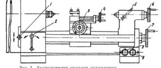
Controls
The operator can control the screw-cutting lathe model 1M61 and control the operation of its components using a number of working parts. In particular, the movement of the quill is set by a flywheel, and this unit is fixed in the tailstock thanks to a special stop. The tailstock itself is fixed on the frame guides using the appropriate handle. The machine carriage also requires reliable fixation when performing end work, which is ensured by a separate screw.
Controls
The handles located on the front part of the 1M61 frame are used to control such processes in the operation of equipment as:
- selection of spindle speed;
- starting the rotation of the lead screw or roller;
- movement of the upper part of the caliper;
- feed parameters;
- setting the parameters of the thread to be cut and turning on the reverse of the lead screw;
- turning on and off the lead screw nut;
- turning on and off the safety clutch;
- selection of the type of thread to be cut;
- enabling direct and reverse rotation of the spindle head.
The 1M61 model machine also has a number of other controls. This:
- a button used to engage and disengage the thread cutting rack with the pinion shaft;
- handle for turning and securing the cutting head;
- load degree indicator;
- button to turn on the electrical power and local lighting of the work area;
- button to start the electric pump that supplies coolant.
Kinematic diagram of 1M61 (click to enlarge)
Device of gearboxes and feeds
The movement of the lathe support in the longitudinal and transverse directions is ensured by the feed box. It is also used to set the parameters of the thread being cut. The machine passport contains a special table from which you can select the feed rate suitable for performing a certain technological operation. To make this table convenient to use, it contains the following information:
- recommendations for choosing replacement gears;
- positions of the box handle at which certain feed values are set;
- recommendations for setting feedbox parameters when cutting threads with a certain pitch.
The gearbox of the 1M61 machine, with the help of which a certain rotation speed of its spindle unit is set, consists of a reversible electric motor, a V-belt drive and a set of gears with different parameters. At the same time, the machine spindle can operate at 24 speeds, 12 of which are obtained using override gears, and the remaining 12 are achieved by the spindle directly through a gear coupling.
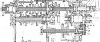
Gearbox device
Feed box device
On the front of the gearbox there are three handles, one of which is responsible for switching gear blocks, the second turns on the overdrive or gear clutch, and the third allows you to change the direction of rotation of the lead screw, which is necessary when performing thread cutting. The gearbox also contains a multi-disc electromagnetic clutch, which is responsible for braking the spindle.
Technical capabilities of the machine
As mentioned above, the spindle of the 1M61 lathe can rotate in forward and reverse directions at one of 24 possible speeds. The technical characteristics of the gearbox allow the spindle to rotate at a frequency in the range of 12.5–1600 rpm. The diameter of the through hole in the spindle assembly is 35 mm, which allows you to insert a rod with a diameter of 32 mm. The end of the spindle, according to GOST 12593, has a standard size of 6K, and its internal cone, according to GOST 13214, corresponds to category M5.
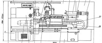
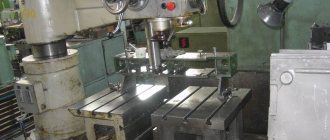
Appearance of the machine 1M61
The design and technical capabilities of the tailstock quill allow it to move a distance of up to 10 cm. A tool whose holder height does not exceed 25 mm can be placed in the tool holder of the 1M61 machine. It should also be noted the following characteristics of the machine of this model:
- center height – 17 cm;
- the maximum length of the workpiece surface that can be turned on the equipment is 64 cm;
- The maximum length of the workpiece that can be installed on the machine for processing is 100 cm.
Electrical circuit diagram
Feeds made on the 1M61 lathe are characterized by the following parameters:
- in the longitudinal direction – 0.08–1.2 mm/rev;
- in the transverse – 0.04–0.6 mm/rev.
The unit support can move:
- in the transverse direction – up to 20 cm;
- longitudinally – up to 60 cm.
The upper part of the support, which is called the slide, can move up to 12 cm, and its carriage, which moves in the longitudinal direction, can move up to 60 cm.
The design of the lathe of this model is so simple, as evidenced by reviews of the equipment, that you can learn how to use it even by watching a training video.
met-all.org
Electrical diagram
An asynchronous electric motor of type AO2-61-4 13 kW is the main unit that drives the system. Just press the “Start” button for this device to start working. With the help of a friction clutch, activated from the handle, similar parts of the mechanism are controlled. Depending on whether the clutch is turned on or off, the mechanism reacts differently to the start of operation.
1.1 kW – engine power responsible for working feeds.
Kinematic diagram
Multi-speed motors are also used to turn on devices, but quite rarely. Single-speed devices remain the main ones for such schemes.
From the engine the movement goes to the gearbox. V-belt transmission takes part in this process. The gearbox contains 6-8 shafts. To these are added gear-shaped wheels. For convenience, Roman numerals are used when numbering shafts. The spindle speed may vary depending on certain conditions. Two friction clutches are responsible for the reverse movement of the same model.
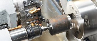
Operating principle of a lathe
The workpiece is secured in a chuck mounted on a spindle. The resulting spindle rotation comes from the main motion electric motor via a V-belt drive.
The tool performs only linear movements in the longitudinal or transverse direction.
A cone installed in the tailstock quill supports a long workpiece or to keep it from bending under high loads during turning. The axial tool that processes the holes is also fixed in the tailstock.
The 1a616 lathe, the operating instructions and passport of which can be found on the Internet in the public domain, in addition to turning, drilling and boring, can perform the following operations:
- form turning;
- corrugation;
- running-in;
- deployment;
- countersinking.
You can work on the machine with tools made of high-speed steels and prefabricated cutters with carbide plates.
Kinematics
The kinematic diagram of the machine allows for the following types of movements:
- Main movement: n dv · i pp · iv = n sp → n sp. The gearbox is adjusted based on the condition: iv = n sp / n dv · i pp.
- Feed movement: S pr = n dv · i pp · i s. The feed box is adjusted based on the condition: is = S pr/ n dv · i pp.
- Screw-cutting movement: t nr = t xv · i pr · i cm · i pp. Adjustment: i pr = t nr = i cm / ( t xv · i pp), where: i pr – gear ratio of gears from the spindle to the replacement wheel guitar, i pr = 48/68·34/36·36/48;
- i pp – gear ratio of the gearbox;
- i cm – gear ratio of replacement wheels.
Electrics
Electrical equipment on the 1a616 machine is similar to 1b61. These are electric motors, fuses, switches, relays, transformers and local lighting. The power supply and circuit diagram are presented in the passport for the machine.
At the time when the machine was mass-produced, it was equipped not only in workshops and workshops at enterprises, but also in rural workshops. In remote areas, the voltage in the electrical network was 220 V. Therefore, PS8S motors operating on direct current were installed on model 1a616k machines. They provided smooth braking without excessive heating.
The lighting of the working area is organized through a step-down transformer and is 36 V.
Operation and repair
Documents for the machine contain instructions for safe operation, maintenance and repair periods, and lubrication intervals. Installation standards and foundation requirements are also displayed.
Indoor operating parameters:
- humidity – 80%;
- temperature – 10°С – 30°С;
- type of production – serial, piece.
For long-term operation, the recommended overhaul cycle is 5 years (with two shifts). The overhaul cycle includes the following regulations: inspection - 10, minor repairs - 5, medium repairs - 2. The list of work performed can be found in the machine passport.
Guitar tuning diagram
Transmission of rotation and torque is the main purpose of this part. It is equipped with replaceable gears, which provide the most precise adjustment of the parameters.
Replacement of parts is carried out depending on the regulations or the degree of wear.
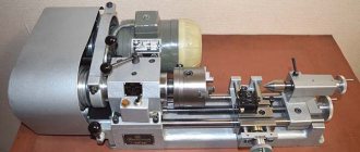
1U61M – Universal screw-cutting lathe
Buy machine bearing with delivery
Specifications:
Model 1u61m machines are designed to perform any turning work in mechanical engineering, as well as in mechanical workshops of industrial and agricultural enterprises.
Maximum length of workpiece processed, mm 500
Largest diameter of the workpiece, mm:
– above the frame 320 – above the support 165 – rod 25
Number of spindle speeds 18 Spindle speed range, rpm 25. 2000 Limits of longitudinal feeds, mm/rev 0.032. 0.5 Transverse feed limits, mm/rev 0.013. 0.2
Limits of pitches of cut threads:
– metric, mm 0.2. 7.0 – modular, module in mm 0.1. 3.5 - inches, thread per inch 0.013. 0.2
Largest cross-section of cutters, mm 20 x 20 Number of tool positions 4 Size of the internal cone of the Morse spindle 4 Size of the internal cone of the Morse tailstock quill 3 Maximum movement of the quill, mm 90 Drive power of the main movement, kW 3 Dimensions, mm 1800 x 750 x 1350 Weight, kg 900
Controls
Elements that include functions and movements on the machine:
- spindle speed setting handles;
- feed selection handles;
- selection of thread pitch;
- threaded screw connection;
- feed rotation direction;
- overkill;
- turning on cross feed;
- rotation and clamping of the tool holder;
- caliper screw;
- “Start”, “Stop” buttons;
- quill clamping;
- tailstock clamp;
- tailstock extension;
- inclusion of coolant;
- power switch;
- reverse rotation of the cartridge;
- uterine nut closing handle;
- longitudinal movement steering wheel;
- spindle rotation starts.