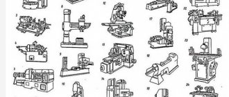
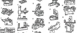
Metal lathes, in general, have a roughly similar layout - a diagram of the arrangement of components. In this article we will list and describe the main components, the principle of their operation and purpose.
The main nodes are:
- bed;
- headstock;
- spindle;
- feed mechanism;
- caliper;
- apron;
- tailstock.
Main components of a metal lathe
Video lesson about the construction of metal lathes
bed
The main fixed part of the machine is the bed, consisting of 2 vertical ribs. Between them there are several transverse crossbars that ensure the rigidity and stability of the stator.
The bed is located on legs, their number depends on the length of the bed. The design of the cabinet legs is such that they can store the tools necessary for the operation of the machine.
The upper transverse rails of the frame serve as guides for the movement of the caliper and tailstock along them. Comparing machine diagrams, it is easy to notice that in some designs two types of guides are used:
- prismatic for moving the caliper;
- flat guide for tailstock travel. In very rare cases it is replaced by a prismatic type.
Headstock
The parts located in the headstock serve to support and rotate the workpiece during processing. There are also units here that regulate the speed of rotation of the part. These include:
- spindle;
- 2 bearings;
- pulley;
- gearbox responsible for adjusting the rotation speed.
The headstock is separate from the machine
The main part of the headstock in a lathe is the spindle. On its right side, facing the tailstock, there is a thread. Chucks that hold the workpiece are attached to it. The spindle itself is mounted on two bearings. The accuracy of the work performed on the machine depends on the condition of the spindle assembly.
Gearbox top view
In the headstock there is a guitar of interchangeable gears, which is designed to transmit rotation and torque from the output shaft of the gearbox to the feedbox shaft for cutting various threads. Adjustment of the caliper feed is carried out by selecting and rearranging various gears.
Spindle
It is unlikely that you can still find a metal lathe with a monolithic spindle. Modern machines have hollow models, but this does not simplify the requirements placed on them. The spindle body must withstand without deflection:
- parts with heavy weight;
- maximum belt tension;
- cutter pressure.
Special requirements are imposed on the journals on which they are installed in bearings. Their grinding must be correct and clean, surface roughness no more than Ra = 0.8.
In the front part the hole has a conical shape.
Bearings, spindle and axle must, when operating, create a single mechanism that does not have the ability to create unnecessary runout, which can result from incorrect boring of the hole in the spindle or careless grinding of the journals. The presence of play between the moving parts of the machine will lead to inaccuracy in processing the workpiece.
The spindle is stabilized by bearings and a tension adjustment mechanism. It is attached to the right bearing using a bronze bushing bored out to the shape of the neck. On the outside, its bore coincides with the socket on the headstock body. The bushing has one through hole and several cuts. The bushing is secured in the headstock socket with nuts screwed onto its threaded ends. The bushing nuts are used to adjust the tension of the split bearing.
The gearbox is responsible for changing the rotation speed. A gear is attached to the pulley on the right, and a gear is mounted on the spindle to the right of the pulley. Behind the spindle there is a roller with a freely rotating sleeve with 2 more gears. Rotational motion is transmitted through the neck to the roller fixed in the brackets. Different gear sizes allow you to vary the rotation speed.
Overkill doubles the number of operating speeds of the lathe. The structure of a metal lathe using brute force allows you to choose an average speed between the base ones. To do this, it is enough to transfer the belt from one gear to the next or set the lever to the appropriate position, depending on the design of the machine.
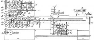
The spindle receives rotation from an electric motor through a belt drive and gearbox.
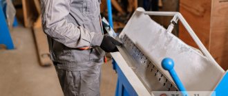
Materials for machine bed guides
Bed guides
Requirements for guide materials
The following technical requirements apply to guide materials.
- Wear resistance. The wear of the guides determines their performance and maintenance of accuracy during the required period of operation.
- A small value of the coefficient of static friction and its insignificant dependence on the duration of stationary contact, a small value of the coefficient of friction of movement, its closeness in magnitude to the coefficient of static friction and a slight dependence on the speed of movement.
- Dimensional stability over time due to internal stresses and resistance to thermal loads, moisture, oils, weak acids and alkalis.
- Sufficient rigidity, taking into account its possible reduction due to additional joints at overhead guides and when using plastics with increased compliance.
- Good machinability to achieve required precision and surface roughness.
- Economic indicators that are determined by comparing the costs of manufacturing guides of a higher technical level and the savings obtained from this.
A sliding friction pair is most often made from dissimilar materials having different compositions, structures and hardness; This eliminates the threat of a dangerous emergency situation - seizure. Bed guides are made of more wear-resistant and hard materials than the guides of moving units. Due to this, longer-term accuracy is achieved, since it is determined mainly by the accuracy of longer guide frames.
Material groups
The materials used for sliding guides of machine tools are divided into three groups: hardened steels and cast irons, non-ferrous alloys, and plastics.
Use of cast iron
Hardened cast iron guides are most often made from SCh20, SCh 25, SCh 30 cast iron in one piece. Heating during hardening is carried out using high-frequency currents or the gas-flame method. Overhead guides are made from the following hardened materials: cemented and hardened steels 20Х and 18ХГТ; high-carbon chromium hardened steels ШХ15, ШХ15СГ, ХВГ, 9ХС, 7ХГ2В, 8ХФ; nitrided steels 38ХМУА, 40ХФ, 30ХН2МА, alloyed and modified hardened cast iron SCh 30 with a hardness for hardening of at least HB 170. The hardness of hardened cast iron guides is HRC 48-53, the hardness of steel guides is HRC 58-62.
Use of non-ferrous alloys
Of the non-ferrous alloys, bronze and zinc alloys are used for guiding moving elements. The best results in terms of wear resistance, absence of scoring and uniformity of feed are obtained by aluminum bronze Br AMts9-2 and zinc alloy TsAM 10-5, working in tandem with steel and cast iron guides. The disadvantage of the TsAM 10-5 alloy is its low wear resistance during abrasive wear, and therefore guides with this material require good protection.
Use of plastics
Plastics are used to guide the moving parts of some CNC machines. The positive properties of plastics are favorable friction characteristics that promote uniform movement of moving devices at low speeds, and the absence of the phenomenon of setting. However, most plastics do not have sufficient rigidity and the necessary resistance to thermal stress, moisture, oil, weak alkalis and acids. The machines use fluoroplastic glued in the form of a tape, filled fluoroplastic with a bronze filler and composite materials based on epoxy resins with additives of molybdenum disulfide, graphite and non-metallic fillers.
Use of composite materials
Composite materials are also characterized by high manufacturability, as they make it possible to produce guides for tables and carriages without further machining. Immediately before application to the surface, a paste-like mastic is prepared from special components (resin, powders, plasticizer and hardener), which is used to cover the guides. The carriage or table with applied mastic is placed directly on the guides of the leveled frame, onto which a thin separating layer of wax coating or a thin layer of lubricant is sprayed to prevent sticking. Hardening time is several hours. If necessary, such a plastic coating can be processed by cutting (planing, milling, grinding, scraping).
Similar materials
Feed mechanism
The feed mechanism tells the caliper the required direction of movement. The direction is set with a bit. The bit itself is located in the headstock housing. It is controlled via external handles. In addition to the direction, you can also change the amplitude of movement of the caliper using interchangeable gears of different numbers of teeth or a feed box.
In the scheme of machines with automatic feed, there is a lead screw and a roller. When carrying out high-precision work, a lead screw is used. In other cases, a roller is used, which allows you to keep the screw in ideal condition longer for performing complex elements.
Caliper
The upper part of the support is the place for attaching cutters and other turning tools necessary for processing various parts. Thanks to the mobility of the support, the cutter smoothly moves in the direction necessary for processing the workpiece, from the place where the support with the cutter was located at the beginning of the work.
When processing long parts, the slide stroke along the horizontal line of the machine must coincide with the length of the workpiece being processed. This need determines the ability of the support to move in 4 directions relative to the center point of the machine.
The longitudinal movements of the mechanism occur along the slide - the horizontal guides of the frame. The transverse feed of the cutter is carried out by the second part of the support, moving along horizontal guides.
The transverse (lower) slide serves as the basis for the rotating part of the caliper. Using the rotating part of the support, the angle of the workpiece relative to the machine apron is set.
Tailstock
The tailstock is movable and is used to secure the part to the spindle. It consists of 2 parts: the lower one - the main plate and the upper one, which holds the spindle.
Sectional view of the tailstock
The movable upper part moves along the lower perpendicular to the horizontal axis of the machine. This is necessary when turning cone-shaped parts. A shaft passes through the headstock wall; it can be rotated by a lever on the rear panel of the machine. The headstock is fastened to the frame using ordinary bolts.
Each lathe is individual in its layout, the device and circuit may differ slightly in detail, but in small and medium-sized machines this option is most common. The layout and layout of heavy large lathes differs depending on their purpose; they are highly specialized.
If you find an error, please select a piece of text and press Ctrl+Enter.
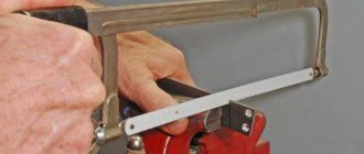
Turning of materials involves processing bodies of revolution with a cutting tool moving along the axis of rotation of the workpiece.
Metals for the production of frames and their main properties
What material are machine beds made of? Traditionally, the main materials for the manufacture of frames for various equipment were metals and their alloys.
In the 17th-20th centuries, cast iron was most popular. It still retains its leading position today, but is gradually retreating under the onslaught of various types of steel, light metal alloys, plastics and composite materials.
Considering the general trend towards reducing the weight and dimensions of equipment and increasing their efficiency, broad prospects are opening up for advanced materials.
For the beds of light and medium-sized machines, such replacement is taking place at an accelerated pace. For heavy equipment, a significant part of the functions of the frames is transferred to the reinforced concrete foundation reinforced with modern materials.
However, for highly loaded machines and production complexes, such as rolling mills, heavy presses, forging machines and steel foundry equipment, special grades of cast iron are still unrivaled.
Its unique ability to withstand large static loads, high guide strength and corrosion resistance distinguish cast iron from competing materials. Cast iron alloys with nodular graphite, modified with cerium additives, have the same performance characteristics as steel and are significantly cheaper to produce.
How the bed and headstock of the machine are arranged
The frame is a supporting element on which all other structural elements of the unit are installed and fixed. Structurally, the frame consists of two walls connected to each other by transverse elements that give it the required level of rigidity. Individual parts of the machine must move along the bed; for this purpose, it is equipped with special guides, three of which have a prismatic section, and one has a flat section. The tailstock of the machine is located on the right side of the bed, along which it moves thanks to internal guides.
The cast lathe bed is reinforced with stiffening ribs and has ground and hardened guides
The headstock simultaneously performs two functions: it gives the workpiece rotation and supports it during processing. On the front part of this part of the lathe (it is also called the “spindle head”) there are gearbox control handles. With the help of such handles, the machine spindle is given the required rotation speed.
In order to simplify the control of the gearbox, next to the shift knob there is a plate with a diagram that indicates how to position the handle so that the spindle rotates at the required frequency.
Speed selection lever for BF20 Yario machine
In addition to the gearbox, the headstock of the machine also contains a spindle rotation unit, in which rolling or sliding bearings can be used. The device chuck (cam or drive type) is fixed at the end of the spindle using a threaded connection. It is this unit of the lathe that is responsible for transmitting rotation to the workpiece during its processing.
The frame guides along which the machine carriage moves (the lower part of the support) have a prismatic cross-section. They are subject to high demands on parallelism and straightness. If these requirements are neglected, it will be impossible to ensure high quality processing.
Bed structure
The main components of a lathe bed design can be seen from the sectional drawing of the lathe bed:
- supporting surface;
- longitudinal ribs;
- transverse ribs connecting longitudinal ones;
- prism-shaped guides;
- flat guides designed for attaching headstocks and moving calipers.
The ribs are formed during the casting of the workpiece for the machine bed
The cross-section of prismatic guides can take various shapes, based on the directions of the forces arising during operation and their magnitude. Both guides must be strictly parallel in space and have a perfectly smooth and even supporting surface. Otherwise, there can be no question of the accuracy of processing parts on the machine.
To achieve this result, they are subjected to high-precision milling or processed on a planing machine. Next comes grinding and scraping. During this processing, geometric parameters are repeatedly monitored for compliance with technical specifications. The final check is carried out after assembling the machine and installing moving parts and components on it.
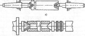
Spindle as an element of a lathe
The most important structural component of a lathe is its spindle, which is a hollow metal shaft with a conical inner hole. What is noteworthy is that several structural elements of the machine are responsible for the correct functioning of this unit. It is in the inner conical hole of the spindle that various tools, mandrels and other devices are fixed.
Spindle drawing of screw-cutting lathe 16K20
In order to be able to install a faceplate or a lathe chuck on the spindle, its design includes a thread, and to center the latter there is also a collar on the neck. In addition, to prevent spontaneous unscrewing of the chuck when the spindle is quickly stopped, some models of lathes are equipped with a special groove.
The results of machining parts made of metal and other materials on the machine largely depend on the quality of manufacturing and assembly of all elements of the spindle assembly. In the elements of this unit, in which both the workpiece and the tool can be fixed, there should not be even the slightest play that causes vibration during the rotational movement. This must be carefully monitored both during the operation of the unit and when purchasing it.
In spindle units, which can be immediately determined from their drawing, sliding or rolling bearings can be installed - with roller or ball elements. Of course, rolling bearings provide greater rigidity and accuracy; they are installed on devices that process workpieces at high speeds and with significant loads.
What is a bed
The bed is the basis of the machine design. All other moving and fixed parts and assemblies are attached to it. Through it, the mechanism rests on the foundation. The bed absorbs all the forces that arise when the tool acts on the workpiece. From certain points on the frame, selected by the origin of coordinates, the movements of the moving parts of the machine are measured. It includes components such as:
- body elements;
- transverse, longitudinal and vertical fastenings and stiffeners;
- guides.
The bed is the longest-lived part of the machine, designed for the entire period of its operation. Engines, drives and working parts can be replaced many times as they wear out; guides only undergo periodic repairs. Guides are used for longitudinal, transverse or vertical movement of the moving parts of the mechanism.
There are two types of guides:
- open, used when processing parts of large and medium weight and small overturning moments;
- closed, used for medium masses of parts and significant overturning moments.
Movable units can move by sliding along guides, or use roller or ball bearings.
In addition to transmitting, distributing and compensating forces, the frame must also be able to dampen vibrations of various frequencies that are excited in the mechanism during its operation.
Caliper structure
A lathe support is a unit that ensures the fixation of the cutting tool, as well as its movement in the inclined, longitudinal and transverse directions. It is on the support that the tool holder is located, moving with it due to a manual or mechanical drive.
Support with carriage for machine Optimum D140x250
The movement of this unit is ensured by its structure, which is characteristic of all lathes.
- The longitudinal movement, for which the lead screw is responsible, is performed by the caliper carriage, while it moves along the longitudinal guides of the frame.
- Transverse movement is performed by the upper - rotating - part of the support, on which the tool holder is installed (such movement, due to which the depth of processing can be adjusted, is carried out along the transverse guides of the support itself, which are shaped like a dovetail).
Quick-change tool holder MULTIFIX cartridge type
The tool holder, also called the cutting head, is installed on the top of the support. The latter can be fixed at different angles using special nuts. Depending on the need, single or multiple tool holders can be installed on lathes. The body of a typical cutting head has a cylindrical shape, and the tool is inserted into a special side slot in it and secured with bolts. There is a protrusion on the bottom of the cutting head that fits into a corresponding slot on the support. This is the most typical tool holder mounting scheme, used primarily on machines designed to perform simple turning work.
Technological processes for manufacturing frames.
A typical technological process for manufacturing frames includes the following basic operations:
— Rough processing of the base (technological base - rough surfaces of the guides).
— Roughing of guides and surfaces perpendicular to them.
— Rough machining of the hole for the spindle (if provided for by the design) and machining of large holes for the shafts.
- Aging.
— Finishing of the base (if provided for in the drawing).
— Finishing of the surfaces of the guides and all other surfaces, the processing of which is possible with this installation.
— Processing of fastening and other small holes.
— Finishing and finishing machining of main holes.
— Final processing of guides.
— Finishing processing of supports for the spindle.
Depending on specific conditions, some operations (transitions) may be combined.
Processing of beds in single and small-scale production can be done by marking manually or using coordinate measuring machines.
In conditions of serial and large-scale production, processing of workpieces is carried out by installing them in pre-configured devices or on satellite devices with automatic alignment of the position of the workpiece.
Roughing of the base is carried out depending on the profile of the contour, the availability of equipment using various methods (methods): face milling, planing, rotary turning, rough grinding, grinding with abrasive belts on belt grinding machines.
| a) b) c) d) planing milling |
| e) – rotary turning e) – milling |
Possible contours of the base of the beds:
The most productive processing method is face milling, but its use is difficult in the following cases: with large cross sections, which necessitates the use of a set of cutters, possible defects in the surface layer of cast workpieces, which causes chipping of the carbide tool.
Planing is inferior in productivity to milling, but has the following advantages: lower cost of the tool and its setup, less sensitivity to surface defects, and removal of large allowances. However, in any case, a technical and economic comparison of treatment options is carried out.
When roughing the base, vertical surfaces or technological plates (special tides) are simultaneously processed, which are subsequently used as technological bases.
Rough processing of guides is carried out by milling, planing, rough grinding on universal and special longitudinal planing, longitudinal milling, multi-spindle machines, as well as on multi-operational CNC machines.
In single and small-scale production, planing is widely used, and the sequence of transitions is determined by the convenience of processing. When processing guides of small width, after cutting a groove with a groove cutter, processing is carried out with shaped cutters along the contour of the guides. Surfaces of large overall dimensions are processed with conventional cutters moving at an angle.
| a B C) |
Milling of guide frames can be done on universal, longitudinal milling, longitudinal planing machines and on multi-operational CNC machines in various ways:
4.
| a) first transition. |
Milling with a standard set of cutters in one or several settings. In this case, the auxiliary time associated with reinstalling the cutters and trial moves increases (Fig. a and b).
| b) second transition. |
When processing in several settings, the entire batch is processed with one machine setting.
In this case, the auxiliary time for reinstalling the cutters falls on the batch and goes into the Tpz category. However, this increases the auxiliary time for installing, securing and removing the frame (according to the number of transitions or operations). The profitability of this method increases as the batch increases. This method is used for guides of simple shape when processed on 2, 4 spindle longitudinal milling machines in mass production. Processing can be carried out on several machines configured for specific operations, which is typical for serial and large-scale production. When processing workpieces in one setup, it is economical to use multi-operational CNC machines. 5. Milling of beds with a special set of cutters on 2 and 4 spindle longitudinal milling machines.
A mandrel with a set of cutters, the profile of which corresponds to the profile of the guides being processed, performs almost complete processing of them. The remaining surfaces are processed in a separate operation. The method is productive and is used in high-volume production. Disadvantage: high cost of setting and sharpening cutters. The set includes both standard and non-standard cutters, high-speed or equipped with carbide. Since the calculation of cutting conditions is carried out using a high-speed tool, in this case the productivity of the carbide tool is reduced.
6. Milling with standard sets of cutters.
Processing is carried out on 4 or 8 spindle longitudinal milling machines. Small sets of standard cutters are used, allowing complete processing of the profile on two 4-spindle or one 8-spindle machines. The method is used in large-scale production.
Finishing of the base is carried out by planing, milling, and sometimes grinding. When processing, carbide tools (mills, cutters) are used.
Finishing of the guides is carried out by planing, milling, grinding, and scraping. When finishing planing and milling, a non-flatness within 0.02 over a length of 1000 and a roughness Ra of no more than 1.25 microns are ensured. If necessary, a tool equipped with plates made of superhard materials (STM) is used. Milling is the most widely used method, providing greater processing productivity.
To compensate for temperature deformations that occur after heat treatment, before finishing milling, the frame can be artificially deformed using a special device with a tension screw in order to obtain a convex surface after milling (Fig. c, b, c, d). After processing, the guides have a convex shape; they acquire a rectilinear shape during the assembly process of the machine when various parts and assembly units are mounted on the frame.
a B C D)
a) – before clamping the workpiece; b) – after clamping the workpiece; c) – after processing the guides and before detaching the workpiece; d) – after detaching the workpiece with machined guides.
The required convexity profile can also be obtained on machines with a copier or on CNC machines with contour control.
The processing of end surfaces can be carried out on longitudinal planing machines with two side supports, on longitudinal milling machines - with two side milling heads with high productivity and processing accuracy. The method is used for processing short beds.
Machining of the ends can be carried out on horizontal boring or multi-operational CNC machines equipped with a rotary table with precise indexing.
Processing can be carried out on end milling machines, which can have 3 spindles: 2 spindles for roughing and 1 for finishing. In one working stroke, complete processing of the ends is carried out.
The processing of mounting holes and other small holes in the frame is carried out on radial drilling and multi-operational CNC machines. Processing is carried out from 4 sides when installing the workpiece in rotary devices along overhead jigs. In large-scale production conditions, processing can also be carried out on aggregate drilling machines. If the use of the machine is irrational or it is impossible to use it, processing of such holes can be done using hand tools (electric or pneumatic drill).
Before final processing of the guides, they are subjected to hardening using surface-plastic deformation methods or heat treatment. Surface-plastic deformation is carried out using ball or roller rolling machines when installed on a frame on longitudinal planing machines. When rolling, the surface layer is hardened to a depth of 0.4 mm, the surface hardness increases by 25 - 30%.
Thermal hardening of the guides is carried out by hardening in special installations with HDTV heating. Hardening is carried out to a depth of 1 to 3 mm, ensuring a hardness of HRC 45 - 52.
Strengthening the guides can be done with a laser beam, the speed of which exceeds the speed of the thermal wave. Due to the high speed of movement and low heating, a high-strength fine-grained structure of the layer surface is formed. Due to slight heating, the thermal deformation of the workpiece in this case will be less.
Finishing methods for processing guides are grinding, fine milling, scraping, and sometimes fine planing.
Grinding is the most common method for finishing guides, providing accuracy within 0.01 mm over a length of 9000 mm.
When using CBN wheels, the surface quality is improved, high accuracy is 0.005 mm over a length of 1000 mm, roughness Ra = 0.63–0.16 µm, and the likelihood of burns is reduced.
Machine time is approximately three times less compared to processing with abrasive wheels.
Scraping is used in the following cases: when it is impossible to obtain high precision by cutting (0.002 mm at a length of 1000 mm), in the absence of the necessary equipment, when processing hard-to-reach places, edges, ends, to improve the quality of the surface by creating oil pockets on it that ensure the retention of thin layers of lubricant.
Fine milling with a tool equipped with STM, in some cases, can replace grinding and scraping. Fine milling ensures improved surface quality due to lower temperature deformations and increases processing productivity.
In some cases, fine planing can be used on carefully calibrated longitudinal planing machines with wide cutters made of high-speed material.
Control of beds.