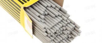
How to cook with welding electrodes?
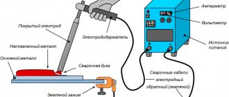
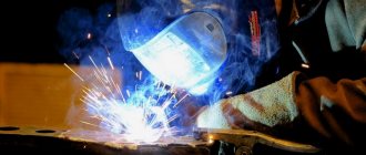
During manual arc welding, performed using coated metal electrodes, the welding arc burns between the metal workpiece and the electrode, melting the coating and the metal of the electrode rod.
Simultaneously with melting, the edges of the welded product melt. You can buy welding electrodes from us from 80 rubles per kilogram! (go to catalog)
Picture 1.
Welding process diagram
As can be seen in Figure 1, the elements of a coated metal electrode are the electrode rod and its coating. The first is made of a special welding wire, and the coating is made of a multicomponent alloy of metals with their oxides. All components of the mixture depending on their functional purpose. Below is their classification.
- Slag-forming:
- insulating (protect the melting metal from the action of active gases contained in the atmospheric air);
- refining;
- deoxidizers;
- alloying.
- ionizing gas;
- shielding gas;
Types and characteristics of coated electrodes
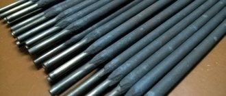
The element has the form of a coated metal rod. To coat its surface, a powder from a mixture of different components is used. The technological qualities of the coated electrode depend on the composition of the coating and the quality of its application.
Rods are classified according to several criteria.
By purpose:
- U – for joining carbon and low-alloy steels.
- L – structural steels with alloying additives.
- T – alloyed heat-resistant steels.
- B – high-alloy steels with specific properties.
By coating thickness : thin, medium, thick and extra thick.
By type of coverage:
- A – sour;
- B – basic;
- C – cellulose;
- R – rutile.
Sour (A)
Contain:
- ores and materials with a high oxygen content (granite, hematite) - provide slag protection;
- ferroalloys – reduce iron from oxides and remove oxygen;
- organic impurities (dextrin, starch) – gas protection.
Welding with such electrodes can be carried out in all positions with constant and variable power sources.
Not suitable for cramped conditions.
Basic (B)
The composition of the coating includes:
- ferroalloys;
- calcium fluoride compounds.
Purpose – welding in any position with direct current. The use of alternating current requires the addition of stabilizers to the coating.
Basic electrodes are used for welding critical structures made of alloy and low-carbon steels and parts with large cross-sections.
Cellulose coated (C)
Contain:
- oxycellulose;
- ferroalloys;
- rutile.
The electrodes are suitable for DC welding in any spatial arrangement.
They are often used to connect pipeline joints.
Rutile (R)
Includes:
- rutile concentrate (titanium oxide);
- calcium carbonates (muscovite, marble, talc, magnesite, cellulose, ferroalloys).
Electrodes are used to connect low-carbon steels with alternating and direct current in any location in space.
Technique for forming a weld seam
The process of ignition (excitation) of the welding arc must be preceded by the installation of a given welding current - its value is determined by the brand of the electrode, the spatial position of the seam, and the type of welded joint.
Ignition can be carried out according to two schemes:
- The electrode is placed perpendicular to the surface to be welded, a light (without force) touch is applied to the welding site, after which the electrode is raised up, approximately 25 cm.
- Ignition of the arc in the second way is similar to lighting a regular match.
After the arc breaks, it is re-ignited in front of the crater - from the base metal to the deposited metal - this ensures the removal of contaminants accumulating in the recess by lifting them to the surface. Then welding is carried out in the required direction.
The choice of arc ignition method depends on two factors - welding conditions and the experience of the welder.
Types and methods of electric arc welding
The type of electric arc welding used is determined by:
- weldable materials;
- thickness of workpieces;
- welding conditions.
According to the degree of automation of the arc welding process, there are:
- manual electric arc welding;
- semi-automatic - instead of a rod, a welding wire is used, which is fed into the working area by a special mechanism; the supply of protective gases is also automated;
- automatic - Carried out in an atmosphere of protective gases without human intervention.
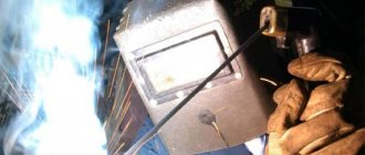
Manual arc welding
Semi-automatic arc welding
Semi-automatic welding scheme
According to the type of electrode used, welding is divided into: consumable (including semi-automatic) and non-consumable, used only as a current conductor to the arc zone.
Electrode movement and placement
The spatial location of the electrode is determined by the position of the weld, which can be:
- lower;
- ceiling;
- horizontal/vertical on a vertical surface.
Welding vertical seams can be done from bottom to top or top to bottom.
During the welding process with a lower seam location, the electrode is inclined relative to the vertical in the direction of welding.
There are two ways to move the electrode: “away from you” or “towards you”.
If during the welding process the end of the electrode does not make transverse oscillatory movements, then the width of the bead is 80-150% of the diameter of the electrode. Such rollers are called narrow or thread seams. They are used when creating the initial layer of a multilayer weld and when welding metals of small thickness.
The middle seams (rollers) are formed due to the oscillatory movements performed by the end of the electrode. The width of such rollers, as a rule, does not exceed 2-4 electrode diameters.
Figure 2 schematically shows the oscillatory movements that the end of the electrode can perform.
Figure 2.
The main options for the trajectories of transverse vibrations performed
by the end of the electrode
CHAPTER 2. Manual arc welding with a consumable electrode
2.1 Scheme of the process of manual arc welding with a covered electrode
Manual arc welding with a consumable electrode ( 111 Manual metal arc welding
, or
Shielded metal arc welding
,
USA
- symbol of the process according to GOST R ISO 4063-2010) - fusion welding, in which heating is carried out by a welding arc and which is performed with a consumable (consumable) electrode.
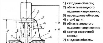
The diagram of manual arc welding with a metal coated electrode is shown in Fig. 2.1. The arc is excited when the electrical welding circuit is briefly closed by touching the metal being welded with the end of the electrode. During the welding process, as the electrode melts, it is brought to the workpiece, simultaneously moving along the joint and across the joint to obtain the required shape and cross-section of the seam.
Rice. 2.1. Scheme of manual arc welding with coated electrodes: 1
- slag crust;
2
- weld;
3
- liquid slag film;
4
- gas protection;
5
— drop of electrode metal;
6
- electrode;
7
— electrode coating;
8
— welding arc;
9
- weld pool;
10
- base metal of the part being welded
When welding with a coated electrode, the rod and coating melt. The melting coating produces slag and gases. The slag layer protects the metal from interaction with oxygen and nitrogen in the air. The gases push air away from the melting zone (arc zone) and provide additional protection from contact with it.
The main advantages of this welding method are the versatility and simplicity of the equipment, but its disadvantage is low productivity, which is due to the low permissible values of current density and the fact that the formation of the weld occurs mainly due to the electrode metal.
The most widely used method is manual welding with a direct electric arc. The best results are achieved when welding with a short arc, the length of which usually does not exceed 0.5...1.1 the diameter of the electrode, a current strength of 90...350 A and an arc voltage of 18...30 V. With a long arc length, oxidation of the electrode metal and spattering increase, and the depth decreases penetration.
2.2Coated electrodes for arc welding
The electrode for manual arc welding (Fig. 2.2) is a rod 1
up to 450 mm long, made of welding wire, on the surface of which a coating layer is applied 2 .
The left end of the electrode in a section 20...30 mm long is freed from the coating in order to clamp it in the electrode holder to obtain electrical contact. The end of the other end is cleared of coating to allow the arc to be excited by touching the workpiece with the electrode at the beginning of the welding process.
Rice. 2.2.Scheme of a coated electrode for manual arc welding: 1
— rod made of electrode wire;
2
- coating;
d
—diameter of electrode wire, mm;
D
—diameter of the coated electrode, mm
According to GOST 9466-75 “Coated metal electrodes for manual arc welding of steels and surfacing. Classification and general technical conditions" in accordance with ratio D
/
d
distinguish electrodes with thin coating (
D
/
d
< 1.2) - marked M, medium coating (1.2 <
D
/
d
< 1.45) - C, thick (1.45 <
D
/
d
< 1 .8) - D and especially thick coating (
D
/
d
> 1.8) - G.
The electrode coating is a mixture of substances applied to it to enhance ionization, protect against the adverse effects of the environment and metallurgically treat the metal of the weld pool. Ionizing, gas- and slag-forming, alloying, deoxidizing, binding and molding components are introduced into the electrode coating.
Ionizing or stabilizing components ensure stable arc burning. They contain elements with low ionization potential, such as potassium and calcium, which are found in chalk, feldspar and granite, as well as sodium, etc.
Gas-forming components are used These include both organic substances (starch, food flour, dextrin, etc.) and inorganic (usually carbonates: marble CaCO3, magnesite MgCO3, etc.). Gas protection is formed as a result of the dissociation of organic substances at temperatures above 200°C and carbonates at temperatures around 900°C.
Slag-forming components are introduced The following ores and minerals are used as slag-forming components: ilmenite, rutile, feldspar, silica, granite, marble, fluorspar.
Alloying components are intended Alloying elements are chromium, manganese, titanium, vanadium, molybdenum, nickel, tungsten, etc. Alloying elements are introduced into the coating in the form of ferroalloys and pure metals.
Deoxidizing components are used These include elements that have a greater affinity for oxygen and other elements than iron (when welding steels), the oxides of which must be removed from the weld metal. Most deoxidizers are introduced into the electrode coating in the form of ferroalloys.
Binding components are used Most often, aqueous solutions of sodium (Na2O × SiO2) or potassium (K2O × SiO2) liquid glass serve as binding components.
Molding components are substances
The following requirements apply to electrode coating:
§ ensuring stable arc burning;
§ obtaining weld metal with the required chemical composition and properties;
§ calm, uniform melting of the electrode rod and coating;
§ formation of a high-quality weld and the absence of pores, slag inclusions and other defects;
§ easy separation of slag from the weld surface after cooling;
§ good technological properties of the coating mass, which do not complicate the electrode manufacturing process;
§ satisfactory sanitary and hygienic working conditions during the manufacture of electrodes and welding.
Types of electrode coatings are established by Electrodes are distinguished:
§ with acid coating - A;
§ main coating - B;
§ cellulose coating - C;
§ rutile coating - P;
§ other types of coating - P.
If there is a coating of a mixed type, use the corresponding double designation. If the coating contains more than 20% iron powder, then the letter Z is added to the designation of the type of coating.
2.3 Technological parameters of the electrode melting process
Technological characteristics of electrode melting are determined experimentally. They allow one to judge the productivity and efficiency of the welding process with electrodes of a particular brand.
Melting coefficient a
p, g/(A × h), determined by the formula
A
p =
G
p /(
I
st
T
o),
where G
p is the mass, g, of the electrode metal melted during the
arc burning
o I
St - welding current strength, A.
For electrodes containing additional metal in the coating (for example, iron powder), the mass of molten metal G
p, g, is defined as
G
p =
G
e +
G
d,
where G
e is the mass of the molten part of the metal rod of the electrode, g;
G
d - mass of molten additional metal contained in the electrode coating, g.
Expression for deposition coefficient a
n, g/(A × h), written as
A
n =
G
n /(
I
st
T
o),
where G
n - mass, g, of metal obtained from the metal rod of the electrode and additional metal (if it was contained in the electrode coating) and deposited during the time To
,
h, at a welding current strength of I St
A.
Loss coefficient Y %, calculated by the formula
Y = [( G
p -
G
n)/
G
p] × 100,
characterizes the loss of electrode metal due to evaporation, spattering and oxidation.
Expression for coating mass coefficient K
n, %, has the form
TO
p = (
G
p /
G
m) × 100,
where G
n is the mass of the coating on the electrode, g;
G
m is the mass of the metal of the part of the rod that has a coating, g.
The values of the considered coefficients depend on the brand of electrode (composition of the metal rod and coating), the type and polarity of the current, etc. The most common electrodes intended for welding low-carbon steels and do not contain additional metal in the coating, and
p = 7…13 g/(A × h),
and
n = 6…12.5 g/(A × h) and Y = 5…15%.
The considered characteristics of the electrodes are used to standardize welding work and electrode consumption. For example, if the area of weld deposited metal F
n, cm2, and the length of the weld
l
w, cm, then the mass of this metal G n
,
g, is determined by the formula
G
n =
F
n
l
wr,
where r is the metal density, g/cm3 (for most steels r = 7.8 g/cm3).
Based on the passport of the selected brand of electrode, in accordance with its diameter and spatial position of welding, I
w and coefficients a p, a
n
Y and
K
p. The main
is determined
T
o =
G
n /(
a
n
I
st).
The mass of electrodes required
G
e =
K
p
G
n,
where K
p is the coefficient of consumption of electrodes per 1 kg of deposited weld metal, usually K
p
= 1.4...1.9, the value of this coefficient is given in the passport of a specific brand of electrodes.
2.4 Selection of modes when welding with coated electrodes
Welding mode is a set of controlled parameters that ensure stable arc burning and the production of seams of specified sizes, shapes and properties.
The mode parameters are divided into basic and additional. The main parameters include include the composition
The diameter of the electrodes is selected Approximate relationship between metal thickness S
and electrode diameter d when
| S , mm1…2 | 3…4 | 5…10 | 12…24 | 30…60 |
| d , mm2…3 | 3…4 | 4…5 | 5…6 | 6 or more |
Vertical, horizontal and ceiling seams, regardless of the thickness of the metal being welded, are made with electrodes of small diameter (up to 4 mm), since this reduces the flow of liquid metal and slag from the weld pool.
The strength of the welding current is usually When welding seams in the lower position, the current strength is calculated using empirical formulas
I
sv =
Kd
,
where K
— coefficient depending on the diameter of the electrode, A/mm;
d
—electrode diameter, mm.
K value
taking into account d
changes
| d , mm | 2 | 3 | 4 | 5 | 6 |
| K , A/mm | 25…30 | 30…45 | 35…50 | 40…45 | 45…60 |
When welding on a vertical plane, the current the ceiling position - by 15...20% compared to the value selected for the lower position. The type of current and polarity are set depending on the type of metal being welded and its thickness. When welding with direct current of reverse polarity, more heat is generated at the electrode. The modes of manual welding of butt joints of sheet steel are given in table. 2.1.
| Table 2.1. Modes of manual arc welding of butt joints (in the lower position) of sheet steel | |||||
| Sheet thickness, mm | Electrode diameter, mm | Welding current strength, A | Sheet thickness, mm | Electrode diameter, mm | Welding current strength, A |
| 1…4 | 1,5 | 25…40 | 6…12 | 4 | 160…200 |
| 2 | 60…70 | 5 | 220…280 | ||
| 3 | 3 | 100…140 | 13 or more | 5 | 220…280 |
| 4…5 | 3 | 100…140 | 6 | 280…340 | |
| 4 | 160…200 | 7 | 350…400 | ||
The arc voltage during Manual welding can be carried out in all spatial positions of the seam, but welding in the lower position is preferable.
Manual arc welding technology involves performing the following operations: exciting the arc, moving the electrode during the welding process, applying seams in an order depending on the characteristics of the welded joints.
During the welding process, it is necessary to maintain a constant arc length. The length of the arc significantly A long arc promotes more intense oxidation and nitriding of the molten metal, increases spattering, and when welding with coated electrodes of the basic type leads to metal porosity.
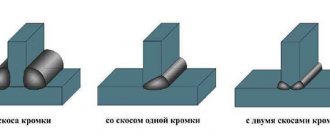
To form a weld, the electrode is given a complex movement in three directions. The first is the translational movement of the electrode in the direction of its axis at the speed of its melting, which ensures the maintenance of a certain arc length. The second movement of the electrode is directed along the axis of the seam and is performed at welding speed. As a result of these two movements, a narrow so-called thread seam, no more than 1.5 times the diameter of the electrode, is formed. Such seams are used to weld thin metal, as well as the root of the seam in multi-layer (multi-pass) welding. The third movement is the oscillation of the end of the electrode across the axis of the weld, which is necessary to form a bead of a certain width, ensure good penetration of the edges and slow down the cooling of the weld pool.
When butt welding without beveled edges, the seam should have a slight widening on one side or both sides of the joint. Butt joints with a bevel of one or two edges are welded using single or multi-layer seams. When welding with a single-layer seam, the arc is excited at the edge of the bevel of the edge, and then, moving it down, the root of the seam is welded. On beveled edges, the movement of the electrode is slowed down in order to better weld them. When the arc passes from one edge to another, the speed of movement of the electrode is increased to avoid burning through the gap between the edges.
Welding of multilayer seams begins by thoroughly welding the root of the seam with an electrode with a diameter of no more than 4 mm, and subsequent seams are welded with widened beads using large-diameter electrodes. The number of layers when welding butt seams is selected according to the ratio:
| Sheet thickness, mm | 1…6 | 8 | 10 | 12 | 14 | 16 | 18 |
| Number of layers | 1 | 2 | 2…3 | 3…4 | 4 | 4…5 | 5…6 |
Welding of connections of critical structures of large thickness (over 25 mm), when volumetric stresses appear and the risk of cracking increases, is carried out using special techniques for filling the seams with blocks or a cascade.
When welding in a cascade, first The third layer overlaps the second and is 200...300 mm longer than it. The layers are fused in this way until the groove is filled in a small area above the first layer. Then, from this area, welding is carried out in different directions using short seams in the same way. Thus, the welding zone is always in a hot state, which prevents the appearance of cracks.
With the block method, reverse-stage welding is used
In multilayer welding, for When surfacing welds with legs larger than 8 mm, welding is carried out in two or more layers.
Below is the number of layers when welding fillet welds depending on the thickness of the metal being welded:
| Thickness of welded metal, mm | 1…5 | 6 | 8 | 10 | 12 | 14 | 16 | 18 | 20 | 22 |
| Number of layers | 1 | 2 | 1…2 | 2 | 2…3 | 3…4 | 5 | 5…6 | 5…6 | 6…7 |
When welding sheets with a thickness of 0.5...3.0 mm, through penetration of the metal by an electric arc (burn-through) is possible with the formation of holes that are difficult to subsequent welding. At the same time, due to the difficulty of regulating the heating of the edges, in addition to burn-throughs, lack of fusion, fistulas, etc. are formed in such seams. To ensure the required quality of welding of thin sheet metal, flanging of the edges is used, temporary heat-removing pads, remaining pads or meltable elements, electrodes with a special coating and special welding equipment.
To select the electrode diameter and current strength when welding thin-sheet steel, you can use the data in Table. 2.2.
| Table 2.2. Electrode diameter and current when welding butt joints of thin sheet steel | ||
| Metal thickness, mm | Electrode diameter, mm | Welding current strength, A |
| 0,5 | 1 | 10…20 |
| 1 | 1,6…2,0 | 30…35 |
| 1,5 | 2 | 35…45 |
| 2 | 2,5 | 50…65 |
| 2,5 | 2,5…3,0 | 65…100 |
According to their length, seams are divided into short (300...350 mm), medium (350...1000 mm) and long (over 1000 mm). Short seams are welded from one end of the seam to the other (per pass); seams of medium length - from the middle of the connection to the ends; long seams - using the reverse-step method, in which the weld is made in successive sections in the direction opposite to the seam increment (Fig. 2.3). The length of the step (section) is 100...350 mm, when welding thin metal the steps are shorter, when welding thick metal the steps are longer.
Rice. 2.3.Methods of making seams: a
— welding “on pass”;
b
- welding from the middle to the ends;
c—e
—making long seams using the reverse-stage welding method;
1
-
10
,
1a
-
4a
- sequence of movements of the electrode in the order and direction of welding (shown by arrows); A is the general direction of welding; I, II - seam layers
With an increase in metal thickness (over 15...20 mm), volumetric welding stresses in welded joints increase, which creates the risk of cracks occurring and developing in the seams. To avoid such phenomena, welding of thick sheet steel is carried out in various ways (Fig. 2.4).
Rice. 2.4. Welding of metal parts of large thickness: a
- double layer;
b
- blocks;
c
- cascade;
I—III—areas of the weld; 1
-
8
- sequence of welding using different methods
Metal with a thickness of 15...20 mm is welded using the double layer method . In section I (Fig. 2.4, a
) with a length of 250...300 mm, the first layer of the weld is deposited, the slag is immediately cleaned off from it, and the second layer is applied over the hot metal of the first layer (with a temperature not lower than 150...200°C). In the same sequence, the seam is welded in sections II, III and subsequent ones.
Metal with a thickness of 20...25 mm or more is welded in blocks or in cascades (sections). When welding in blocks ( Fig. 2.4, b
) a multi-layer seam is performed in separate sections, and the gaps between them are filled before welding of the entire seam is completed.
When welding in a cascade ( Fig
, each
With U-shaped edge shaped preparation - 500...800 mm. In this case, each layer of the section is divided into steps 150...200 mm long and welding is performed using a reverse-step method. As the thickness of the metal increases, the length of the sections is reduced. Metal with a thickness of 30 mm or more is welded simultaneously by two welders located on opposite sides of the joint.
Making welds
The length of the seams provides the following classification:
- long (over 1 m);
- medium (0.35-1 m);
- short (0.25-0.3 m).
The section size determines the division of seams into single-pass or single-layer, as well as multi-pass or multi-layer.
The advantage of single-pass welding is efficiency and productivity. Disadvantage: insufficient ductility of the weld metal due to its rough columnar structure and too large overheating zone.
When multilayer welding, each underlying bead undergoes preliminary heat treatment before applying the next bead - this creates a crushed structure of the seam and joint material.
Multilayer welding involves three options for the arrangement of layers:
- sequential application of layers along the length of the seam;
- "cascade" method;
- “slide” overlay.
The last two methods are used when welding metal products with a thickness of more than 25 mm. The execution of multi-layer seams should be accompanied by increased attention to the creation of the first layer created at the root of the seam. The further strength of the entire seam depends on the penetration of the latter.
Technology
To ensure a strong fusion of the ends of the parts, which will not have tubercles or irregularities, you need to adhere to a certain technology.
In the technique of electric arc welding with coated electrodes, there are two types of work that allow you to ignite the beam:
- point view: the blows resemble points that the master makes as a guide to the details;
- striking: the action is similar to striking a lighter.
Different types of metals are characterized by different characteristics: positive and negative. For example, some of them are much more difficult to set on fire than others and vice versa.
Basically, the characteristics of the conductor will depend on its coating, as well as the type of arson.
The new device is easier to work with. To make an arc, you can only touch the metal with it, and then raise it to a height of about 2-3 millimeters.
Newbie mistakes
So, we already know how to use electric arc welding with coated electrodes correctly. There are six types of errors:
- size, shape are incorrect;
- gaps and cavities are left;
- deformations have formed;
- some parts are uncooked;
- too hard inclusions;
- other disadvantages.
We propose to study the most common mistakes that beginners make when electric arc welding with coated electrodes. It’s good to know them so as not to repeat them yourself.
- Arc length. It's either too short or too long. If the length is short, the weld is welded hard, uneven, and there is a lot of slag. If it’s the other way around, the metal splashes very intensely, and because of this, the path is also crooked. Also, the large distance between the arc and the electrode creates an unstable arc, so there are a lot of “holes”.
- Speed. Soldering at too high or too low a speed will result in poor performance. For example, too fast control of the device leads to the formation of a curved path with a high influx of slag. The roller is thin, so the product is not welded firmly. If the pace of work is too slow, the seam comes out thick and bulky.
- Settings. You need to set the amperage correctly on the device. It is designed according to the types of parts that the master works with. If the intensity is too low, the bead will be thin, which means the fusion will be weak. The roller that is created at high voltage is flat and full of slag.
- Preparation. Insufficient surface preparation is a very common mistake. This makes the path frail, with unevenness and holes. It is very important to thoroughly clean the surfaces and the device from dirt, varnish residues, gunpowder, oil, etc. Otherwise, the master will end up with a squishy seam with a bunch of unassembled residues.
- Incline. To ensure a strong alloy, it is important to maintain the correct degree of inclination of the conductor when welding. If the slope is too horizontal, the tape will be crooked and scaly. If the slope is perpendicular, then the flakes are combined into a huge roller, which remains a “storage” for slag.