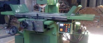
Device for processing guide beds of lathes
Lathes are used to process cylindrical parts.
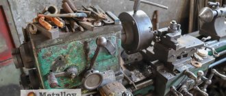
They include many varieties that differ in size and additional functions. Industrial models such as the 16K20 lathe are very common and widely used in modern industry. In order for the device to function normally, you need to know all the features of its parts. The lathe bed serves to secure almost all mechanisms and components that are used on this equipment. It is often cast from cast iron to create a massive and durable structure that can last a long time. This is due to the fact that it will be subject to heavy loads. You should also not forget about stability, since massive large models use enormous energy during operation and the base must resist the load well.
photo: lathe bed
The machine bed and guides are attached with bolts to the stands or paired legs. If the device is short, then two racks are used. The longer it is, the more racks may be required. Most cabinets have doors, allowing them to be used as drawers. The guides should be treated with great care and avoided from being damaged. It is not advisable to leave tools, workpieces and other products on them. If you still have to place metal objects on them, then you should put a wooden lining before doing this. For better care, before each use of the machine, the frame must be wiped and lubricated. When the work is completed, shavings, dirt and other unnecessary objects should be removed from it.
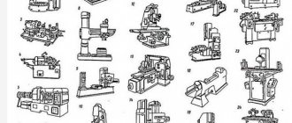
The design features of the frame of metal-cutting machines may differ depending on the specific model, since they are designed for the convenient and safe placement of all equipment components. But the basic principles remain the same in many cases, so we can look at the basics using popular models as examples.
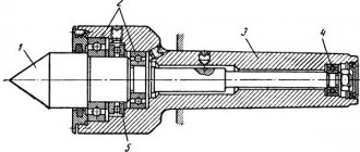
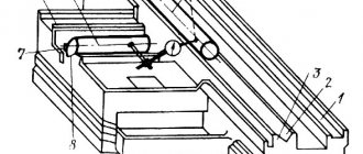
photo: construction of a cast iron bed
- Longitudinal rib;
- Longitudinal rib;
- A transverse rib that serves to connect the longitudinal ribs;
- Prismatic guides of longitudinal ribs;
- Flat guides, which serve to install the tailstock and front headstock, as well as to move the caliper along them;
It is worth noting that the cross-section of the bed guides can have different shapes. A mandatory rule is to maintain a parallel arrangement, so that everything should be equidistant from the axis of the centers. This requires precise milling or planing. After this, the grinding and scraping operation is carried out. All this ensures precise processing of products, as well as eliminating problems with the movement of the caliper and the occurrence of shocks.
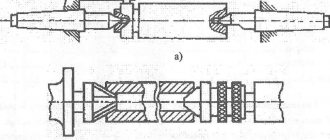
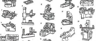
photo: types of machine beds
- The bed of a metal lathe, which is shown in figure “a” under numbers 1 and 2, has a trapezoidal cross-section of guides. In this case, the main emphasis is on a large supporting surface. They have great wear resistance, which allows them to maintain their accuracy for a long time. At the same time, moving the caliper along them requires a lot of effort, especially if it is skewed.
- Figure “b” shows a bed with a flat rectangular cross-section of guides. Unlike the previous one, they already have two stiffening ribs, rather than one, which makes them stronger.
- Figure “c” shows a frame with triangular cross-section guides. Taking into account the fact that a fairly small supporting surface is used here, it is difficult to work with a large weight, so this type is used mainly for small machines.
- Figure “d” shows a frame with a triangular cross-section and a supporting plane. In this case, it is also used for small-sized machines.
If the bed is intended for a heavy machine, then it has not only a large cross-section, but also greater bending resistance. One of the most common is the type shown in Figure “d”. Here the caliper carriage focuses on prism No. 3 in front, and rests on plane No. 6 at the rear. To prevent capsizing, it is held in place by plane No. 7. When tasking the direction, the main role is played by prism No. 3, especially since it absorbs most of the pressure exerted by the cutter.
If there is a recess on the frame near the headstock, then it is used to process large-diameter products. If the product is being processed, the radius of which is less than the height of the centers, then the recess is covered with a special bridge.
Scraping a lathe bed is a technological process during which the bed is aligned to secure the feed box using a frame level. Thanks to this, it will be possible in the future to easily establish the perpendicularity of the mounting surface of the caliper and apron to the feed box.
- First of all, install the frame on a rigid foundation and check the longitudinal direction along the surface level, and the transverse direction along the frame level. Permissible deviations are no more than 0.02 mm per 1 meter of product length.
- Scrape the top surfaces of the guide, first on one side, using a paint straight edge. During this process, it is advisable to periodically check the alignment of the guides.
- Then the surface of the second guide is scraped. The maximum tolerance for deviations here remains the same 0.02 mm per 1 meter of product length.
Grinding a lathe bed consists of the following procedures:
- It is necessary to clean and file away burrs and nicks existing on the surface;
- The bed is installed on the table of the longitudinal planing machine and securely fixed there;
- Next comes the check of the torsion of the guides, which is carried out using a level placed on the bridge of the tailstock;
- During installation of the bed, a slight deflection of the product occurs, which should be corrected by making maximum contact with the table;
- The curvature of the guides is re-checked so that the results coincide with what was before fastening;
- Only after this do they begin to grind all contact surfaces of the product. The procedure is carried out using the end of a cup-shaped circle. its grain size should be K3 46 or KCh 46, and its hardness should correspond to SM1K.
Factory work
As for grinding the steering rack shaft in a workshop or in production, a special machine is used for this, which must be operated by an experienced turner. It is important to know that during operation it is necessary to constantly monitor the shape deviation. It must be in accordance with regulatory documents. Before starting repairs, it is necessary to conduct a visual inspection of the part to make a conclusion about the advisability of grinding the shaft.
Today, a rather important aspect of the procedure has become its cost. It depends on factors such as the type of rod, the amount of work and the thickness of the corroded layer. The main advantage of grinding rack power shafts in workshops is that they have stands for checking the performance of the product. If any shortcomings appear, it is possible to eliminate them immediately.
Metal grinding methods
Currently, a large number of methods for finishing metal have been developed, which are implemented using special machines and equipment. Metal grinding is classified according to the following criteria:
- the chosen method;
- equipment used (special or standardized machines);
- abrasive materials used;
- processing depth;
- required accuracy;
- mechanical or manual grinding.
The main methods include:
- grinding surfaces that have a flat shape (this method is used to process external surfaces that have a given curvature);
- cylindrical grinding;
- centerless processing;
- gear grinding;
- grinding of internal surfaces.
- belt grinding, cylindrical and surface grinding, internal grinding, centerless grinding machines;
- general purpose machines (lathes, milling, drilling);
- special equipment.
Each type of machine is used to perform a whole list of similar operations. For example, the peculiarities of the process of grinding metal with a cylindrical grinding machine consist in performing the operation on cylindrical parts. The internal grinding machine is used for finishing the internal surfaces of metal. All machines are divided into two large categories: with the use of electronic controls (performing CNC operations) and without such equipment. The first type allows you to solve a wide range of problems. They are equipped with a whole range of tools and accessories. The sequence and methods of metal processing are specified by special software.
Machines designed to perform other operations (lathe, milling) are used in conjunction with tools that can be equipped with abrasive material (belt or wheels). The quality of metal grinding depends on the rotation speed and the size of the abrasive chips located on the wheel used.
Special grinding equipment involves performing highly specialized operations. It is capable of solving specific problems at the stage of preliminary or final preparation of parts.
Cylindrical external grinding
Cylindrical grinding has a number of advantages that allow you to obtain high quality and reduce surface roughness:
- parts may have quite large dimensions;
- the machines have the ability to fine-tune technical parameters on which the quality of grinding depends;
- a wide range of manufactured machines (from desktop to large-sized) allows you to select the required copy and solve the problem based on the ratio of efficiency and cost.
Circular grinding of metal is used in almost all branches of machine tool construction, automotive and aircraft construction, and metalworking.
Internal grinding
- rotation of the workpiece and direct feeding of the grinding tool;
- feeding the part to the rotating grinding device;
- combined feed (it can be parallel or transverse).
Internal grinding is used in the manufacture of the following products:
- various bearings (ball and roller);
- vehicle transmission products (shock absorbers);
- hydraulic and pneumatic devices.
Internal centerless grinding allows you to solve the following problems:
- improve the quality of the inner surface of the metal;
- eliminate axial displacement of the finished hole;
- give it the correct round shape of a given diameter.
Gear grinding
- rolling method with continuous grinding;
- the same method with periodic division;
- profile grinding.
The first method is to grind both surfaces of each tooth at the same time. Thanks to this, it is possible to achieve high process productivity. With such processing, it is quite difficult to take into account processing errors, which depend on the tooth pitch. The use of the second method eliminates this drawback. In this case, the grinding speed of the entire gear is reduced.
Profile gear grinding allows you to grind metal in one pass. With the correct setting of the tool position parameters, it is possible to obtain a surface with a high degree.
To improve the quality of the resulting parts, gear honing is used. In this case, instead of the standard abrasive material, a special mixture of white electrocorundum, chromotitanium and boron nitride is used. It has unique abrasive properties. With its help it is possible to obtain the highest degree of grinding.
Centerless grinding
- The first method involves processing workpieces that are long. A prerequisite is to maintain a constant diameter along the entire length of the part.
- The second method is to process surfaces on which there are technological recesses, grooves, and various cutouts. It is used to grind shaped and stepped parts.
In the first case, the tool is fed longitudinally while simultaneously rotating the part around its axis. To obtain the best effect, the axis of the drive shaft during rotation is located at a certain angle relative to the grinding axis. This angle is determined by the diameter and length of the workpieces.
The second method involves changing the feed of the grinding tool depending on the configuration of the metal product. It allows you to obtain high precision and quality of the machined surface.
The centerless grinding method is used in many enterprises that produce products in large quantities. It has high performance. Thanks to its advantages, it allows you to obtain good quality grinding of industrial metal products.
This method is used to process the internal elements of metal parts. The approach to implementing this method is similar to the processing of external surfaces. The grinding wheel is fed into the internal hole of the part.
Sanding flat surfaces
Rough and finishing flat metal grinding is applied sequentially. This allows you to achieve high precision and obtain a perfectly flat metal surface with a minimum roughness index. Surface grinding work is performed on special machines using abrasive wheels of varying precision. Depending on the task at hand, a single-pass or multi-pass metal grinding method is used. The second is performed using fine abrasive, which reduces the impact of forces on the surface being processed, leads to an improvement in temperature conditions, and reduces possible deformation during processing.
Technologically, flat metal grinding is implemented as follows. The part is fixed on a stationary machine table. Fixation can be mechanical or magnetic. Metal processing is carried out using a grinding wheel. During operation, it makes rotational and translational movements.
Crankshaft machines
Today, a good solution would be to use an AMC-SCHOU crankshaft grinding machine.
This equipment is made from heavy-duty castings. The device has a hydraulic supply of the circle, as well as locking pins. A distinctive feature of the device is the fairly rapid regulation of the wheel feed, which is carried out without backlash.
The main procedure required when repairing a crankshaft is grinding. This operation allows you to correct the geometry of the device, correct chips, increase engine life, and also reduce the risk of new problems.
Grinding the crankshaft journals now eliminates scuffing and wear. The process of grinding this device itself is an option that requires special machine equipment, as well as high specialist skills.
Hard turning and grinding – comparison of machining processes
Traditional external plunge grinding
Traditional external plunge grinding as a processing method has been tested by time and many completed projects. However, rich production experience in this case is rather a disadvantage from the point of view of innovative potential, since over the past years almost everything that is possible has already been optimized.
Hard turning
Hard turning often competes with grinding as an alternative technological process. First of all, hard turning has the advantage of being highly flexible. Experts also highly appreciate the fact that processing in this process can also be carried out without coolant. A significant disadvantage of hard turning was and remains the low stability of the technical process. Unpredictable occurrence of chipping and wear of cutting edges at any time can cause failure in the processing process. In addition, standard machine equipment allows for hard machining to achieve a degree of accuracy no higher than IT6.
Grinding with CBN wheels
A significant distinctive feature of plunge-cut grinding with CBN wheels is a significant reduction in the duration of the main processing time compared to traditional grinding methods. Along with the reduction in the main time, a noticeable reduction in the auxiliary time is also achieved due to the high durability of grinding wheels with CBN. The disadvantage of plunge grinding with CBN is primarily that, due to the high absolute cost of the tool, the cost-effective use of this process is limited to serial and mass production only.
High-performance external shaped grinding, or “shaving” grinding, is a variant of the technological process of grinding with CBN wheels, in which the outer contour of the profile of the workpiece is formed due to the movement of a thin grinding wheel controlled by a CNC system. This process is characterized by its high flexibility and is ideal for external cylindrical grinding of workpiece families. The disadvantage is that high speed machining technology and the use of grinding oil require higher investment compared to other processes
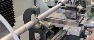
We carefully monitor the quality of all services we provide. Sanding beds was no exception. Once a week, the frames are selectively checked for geometry using an autocollimator. Also, if necessary, the grinding quality is checked for roughness using a Hommel-Etamic T1000 profilometer.
Photo of quality control of grinding bed guides
Photo of the grinding process on an 8 meter Waldrich Coburg machine
Photo of the grinding process on a 4 meter Waldrich Coburg machine and its results
The lathe bed is used for mounting components used on the machine. The frame is made of cast iron. The result is a massive, strong and durable structure, but it is the bed that is subject to the greatest wear during operation of the machine. This affects the accuracy of the parts produced on this machine.
The work of grinding the bed guides restores the geometric characteristics of the machine, and also eliminates burrs, nicks, complex damage and other defects. The bed is installed on the table and aligned using an indicator head. The degree of wear and straightness of the guides are assessed. After which the grinding process itself begins.
Description of the grinding device
Shaft grinding is carried out using a grinding wheel. This circle is a porous body consisting of a large number of abrasive grains. These grains are held together by a binder. In addition, pores are located between these grains and ligaments. The grains themselves are made of very durable material, and their number reaches tens or even hundreds of thousands.
As for the working profile of the wheel for grinding shafts, it consists of cutting edges of abrasive grains. They are located at different distances from the surface. In addition, the grinding process is a procedure during which chips are removed. Due to the fact that large quantities of chips are removed, this leads not only to grinding of the material, but also to a significant release of heat in the contact zone. It is for this reason that this operation is carried out only if there is a constant supply of large quantities of lubricants and cooling substances.
Machining on lathes
Turning of the outer cylindrical surfaces is carried out with pass-through cutters with longitudinal feed, smooth shafts, when installing the workpiece in the centers.
Center holes are processed on lathes, turrets, drills and double-sided centering machines. For centering, standard tool sets are used - combined centering drills, as well as spiral drills and conical countersinks.
Center holes are, as a rule, installation bases, and therefore the accuracy of machining the remaining surfaces of the workpiece depends on the accuracy of their execution.
After trimming the end and processing the hole on both sides, plugs or mandrels with centered holes are inserted into hollow workpieces, or conical chamfers are removed at the edge of the hole, used as technological bases, and then removed during finishing processing.
Stepped shafts are turned according to the scheme of dividing the allowance into parts or dividing the length of the workpiece into parts. In the first case, workpieces are processed with a smaller depth of cut, but the total path of the cutter is large and To sharply increases .
In the second case, the allowance from each stage is cut off immediately due to the processing of the workpiece with a large cutting depth. In this case T decreases, but more machine drive power is required.
It is recommended to process non-rigid shafts with thrust cutters, with a leading angle j = 90°. When processing shaft workpieces with such cutters, the radial component of the cutting force is Ru = 0, which reduces the deformation of the workpieces.
Trimming the ends of the workpiece is performed before turning the outer surfaces. The ends are trimmed with scoring cutters with a transverse feed towards or away from the center of the workpiece. When trimming from the center to the periphery, the end surface becomes less rough.
Turning of roundings between the steps of shafts - fillets is carried out with passing cutters with a rounding between the cutting edges along the corresponding radius with longitudinal or transverse feed.
Turning of grooves is carried out with a transverse feed using groove or shaped cutters, in which the length of the main cutting edge is equal to the width of the groove being machined. Wide grooves are machined with the same cutters, first with a transverse and then with a longitudinal feed.
The processing of holes in the shafts is carried out with appropriate tools fixed in the tailstock quill. The figure on the left shows a diagram of drilling a cylindrical hole in a workpiece.
Boring of internal cylindrical surfaces is carried out using boring cutters fixed in the tool holder of the machine, with longitudinal feed.
Smooth through holes are bored with pass-through cutters; stepped and blind - with persistent boring cutters.
Cutting of processed parts is carried out using cutting tools with transverse feed. When cutting a part with a cutter with a straight main cutting edge (picture on the left), the resulting neck is destroyed and the end of the finished part has to be additionally trimmed.
When cutting a part with a cutter with an inclined cutting edge (picture on the right), the end is clean.
Grinding of the outer conical surfaces of the workpieces is carried out on screw-cutting lathes using one of the following methods.
Wide turning cutters.
They grind short conical surfaces with a generatrix length of up to 30 mm using turning cutters. Grind with transverse or longitudinal feed. This method can be used when chamfering machined cylindrical surfaces.
Rotate the upper support carriage.
When processing conical surfaces, the carriage of the upper support is rotated at an angle equal to half the angle at the apex of the cone being processed. Processed with manual feed of the upper support at an angle to the line of the machine centers (a). In this way, conical surfaces are ground, the length of the generatrix of which does not exceed the stroke of the upper support carriage. Any cone angle of the surface being machined.
By shifting the tailstock housing in the transverse direction.
The workpiece to be processed is placed on ball centers. The tailstock body is shifted relative to its base in a direction perpendicular to the line of the machine centers. In this case, the axis of rotation of the workpiece is located at an angle to the line of machine centers, and the generatrix of the conical surface is parallel to the line of machine centers. In this way, long conical surfaces with a small cone angle (2 a
Turning
The most typical type of parts of bodies of rotation, consisting of a combination of external surfaces (cylindrical, conical, complex shape), is the shaft. Shafts can be made from rolled products, forgings, stamped blanks and castings. The shape of the shafts is: smooth, stepped, eccentric, cranked. By size - small (up to 200 mm long), medium (200 to 1000 mm long) and large (more than 1000 mm long). Workpieces are installed in machine centers or chucks of various types: 3-jaw, self-centering, collet, etc. Processing time should be minimal. When removing an allowance, one proceeds from considerations of a consistent reduction in the rigidity of the shaft, i.e. steps of smaller diameter are processed last. During rough turning, the processing accuracy reaches 14th grade, and the roughness Rz = 40...80 µm. Cutting modes for rough turning:
Semi-finish turning ensures processing accuracy of 9–12 grade and surface roughness Rz = 10…20 µm. Cutting modes for semi-finish turning:
Finish turning ensures processing accuracy of 7–8 quality and surface roughness Ra = 1.25…2.5 µm. Finish turning cutting modes
Fine (diamond) turning is a finishing processing method. When external turning with diamond (CBN) cutters of non-ferrous alloys, an accuracy of 5-6 grades and a surface roughness of Ra = 0.16...0.32 microns are achieved. Cutting modes for fine turning:
For diamond turning, machines of particularly high precision and rigidity must be used. As a tool for fine turning of steels, you can use wide cutters equipped with plates made of T30K4 hard alloy, and for processing cast iron - cutters with plates made of VK2 or VK3 hard alloy. The front and rear surfaces of the cutting inserts must be brought to a surface roughness of Ra = 0.02...0.04 µm. Fine turning with cutters with carbide inserts is carried out at a depth of cut t = 0.05...0.15 mm, longitudinal feed S = 0.01...0.05 mm/rev and cutting speed V = 200...350 m/min. In this case, an accuracy of 6–7th quality and a surface roughness of Ra = 0.32...0.63 microns are achieved. An emulsion is usually used as a cutting fluid. When processing long, low-rigid shafts, fixed and movable steady rests are used. When processing hollow shafts with controlled wall thickness differences, ring (swivel) steady rests are used.
Figure 1- a) roller steady, b) vibration-damping steady
Lunettes serve as additional support that experiences loads. The movable rest, following the cutter, perceives the cutting force. The surface to be treated rests on the cams of the steady rest. In cases where it is necessary to ensure the alignment of the surface being turned with the previously processed one, the cams of the steady rest are installed in front of the cutter, that is, on the previously processed surface. During high-speed cutting, the jaws create significant friction. To reduce friction, steady rests with roller supports are used. During high-speed turning, vibrations often occur, which increase surface roughness and reduce processing accuracy. To eliminate vibrations, steady rests with a vibration damper are used. Belleville springs placed in the vibration damper housing absorb vibrations of the part. At high cutting speeds, the chips have a confluent shape and flow out from under the cutter in a continuous ribbon. Such chips are very dangerous, as they can cause injuries (cuts and/or burns). To crush such chips, special devices are used - chip breakers. In serial and small-scale production, shafts are often processed on CNC machines. In individual production, shaft processing is usually carried out on universal, manually operated equipment.
All about working on a lathe
A wood lathe has one limited function: it only turns a piece of wood. A carpenter gradually turns a finished object from a simple piece of wood: legs for furniture, a lamp body, railing posts, toys, boxes, cups, salad bowls, vases, etc.
Unlike other woodworking machines, which are used only at certain intermediate stages, a lathe is suitable for all operations: from roughing to polishing. The required tools are grooved (cylindrical or V-shaped) and flat chisels, cutters, scrapers of various sizes and shapes. The machine rotates the workpiece, and the hand controls the movement of the cutter.
Machine design with electronic control
- Start-Stop switch
- bed
- Headstock
- Speed switch (with CVT)
- Spindle
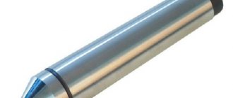
- Lead Center
- Tool support (tool holder)
- Tailstock center
- Tailstock