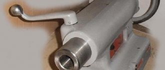
Apron design for a universal screw-cutting lathe
The apron of the screw-cutting lathe is rigidly attached to the front end of the caliper carriage.
The apron converts the rotational movement of the lead screw or lead roller into translational movement of the caliper (feed) along the bed guides. The movement from the running roller is also used to mechanically move the cross slide.
Technical characteristics, photographs and drawings are given on the page Screw-cutting lathe 1K62 .
A lead screw is used when cutting threads. The rotary motion of the lead screw is converted into a translational motion of the caliper (feed motion) using a split nut. The rotation speed of the lead screw, and therefore the feed rate, is controlled by the feed box of the lathe.
The roller is used for all other turning operations. The rotational movement of the running roller is converted into a translational movement of the caliper (feed movement) using a worm on a sliding key, a gear rack mounted on the frame and a gear engaged with the rack. This wheel can be rotated either mechanically - from the drive shaft, or manually from the rotation of the handle (handwheel).
Mechanisms in the apron can convert the rotational motion of the roller into translational motion (mechanical feed) of the caliper cross slide.
To accelerate the movement of the caliper, a separate electric motor is used, which rotates the roller at an increased speed.
A plunger pump provides lubrication of all drive parts, bearing supports and guides of the caliper and carriage. It is mounted on the lower cover of the apron and is driven by the worm gear shaft.
The lead screw is lubricated using a manual oiler with the nut on.
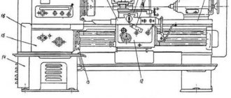
Kinematic diagram of a screw-cutting lathe
The apron of the screw-cutting lathe has four jaw couplings, allowing for forward and reverse movement of the carriage and support. The carriage movements are controlled by the mnemonic handle 25. The direction of activation of the handle coincides with the direction of movement of the support. The activation of fast movements of the caliper in the indicated four directions is carried out by additionally pressing the button 12, built into the handle 25. This and pressing turns on the high-speed electric motor, which, through a V-belt transmission, communicates movement to the drive shaft.
The apron has a blocking device that prevents the simultaneous activation of the longitudinal and transverse feeds of the caliper, as well as a safety cam clutch, which is activated under the influence of forces arising when the apron is overloaded.
To cut a thread, use handle 24 to turn on the nut and disengage the rack and pinion gear by pulling button 6 toward you.
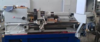
Repair 16k20 - Turning 1K62, 16K20 and modifications
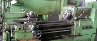
They brought this machine from ferrous metal.
I will be doing a major overhaul. Today I scattered it among the nodes and took some pictures of the process. I think someone will be interested.
If yes, please move the moderators to the appropriate section.
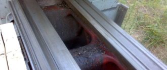
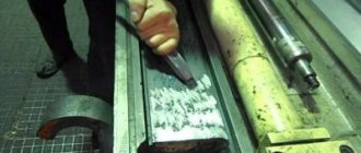
So... We remove all panels and electrics. Everything is clear here. let's skip it. Next, here he is without the shields. The task is to remove the shafts.
We knock out the pins shown by the arrows, the bottom one is pulled out with a pin puller. Unscrew the bolts of the rear support and pull out the studs from it.
In this photo you can see that someone was knocking out the shafts with a hammer and a hammer. There is no need to do this... Just turn on the nut and use the steering wheel to pull the shafts out of the couplings. When the screw comes out, it will hit the rapid feed pulley on the drive shaft and pull it out too. The clutch engagement roller in the landing seat usually sits on the sliding one and will also stretch out without problems.
In my case, the steering wheel is broken,
We turn the gas key by the valve - the rest of the steering wheel.
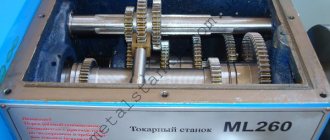
So, the shafts have been removed.
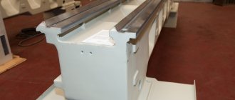
The next step is to remove the apron.
We unscrew the bolts and pull out the studs shown in red arrows. The apron remains hanging on two bolts, indicated by blue arrows. When completely disassembling the machine, I unscrew all the bolts that can be unscrewed with the wrench in my hands, with the exception of two, which I leave so that the unit is held in place (so that several times at a time don’t grab the key, it saves time).
Next, we moor and take off.
www.chipmaker.ru
Description of operating modes of the machine apron
Fig. 9. Diagram of the apron of a screw-cutting lathe
Longitudinal feed of the caliper carriage
The longitudinal feed of the machine support when performing all turning operations, except for cutting threads with a cutter, is carried out using a gear rack 14 mounted on the frame and a gear wheel 17 rolling along it. This wheel can be rotated either mechanically - from the running shaft 1, or manually from the rotation of the handle . Mechanical longitudinal feed is carried out as follows. The long keyway 2 of the running shaft 1 includes the key of the worm 9 sitting on it. Rotating, the worm drives the worm wheel 8. To turn on the mechanical longitudinal feed, you need to use a handle 11 to connect (using a clutch) the worm wheel with the wheel 10. The latter will impart rotation to the wheel 15, and together with it the rack wheel 17, sitting on the same roller, will rotate. This wheel rolls along a stationary rack 14, driving the apron and the caliper carriage along the frame.
Manual longitudinal feed is performed by handle 13 through wheels 12, 15, 17 and rack 14.
Cross feed of caliper slide
To carry out mechanical transverse feed, a bevel gear 7 sits next to the worm 9 on the running shaft, the key of which also slides in the long keyway 2 of the running shaft 1. Rotating with the shaft, the wheel 7 rotates another bevel gear 4 and cylindrical wheels 5, 3, 6 and 21. Using the button 18, you can engage the wheel 21 with the wheel 19. Together with the wheel 19, the screw 20 rotates, carrying out the transverse feed of the cutter. To turn off the cross feed, wheel 21 is disengaged from wheel 19 using the same button 18.
Manual transverse feed is performed by handle 16.
Thread cutting on a screw-cutting lathe
Rice. 10. The device of a split nut (uterine nut) of a screw-cutting lathe
To move the caliper longitudinally when cutting threads, a lead screw 22 is used, to which is connected a split nut (male nut) 23 installed in the apron.
The split nut structure is shown in Fig. 10. When cutting a thread, both halves of the nut 23 are brought together using the handle 25; approaching, they capture the thread of screw 22, during the rotation of which the apron, and with it the support with the cutter, receive longitudinal movement. To move and move apart the halves of the split nut, a disk 24 with two spiral slots 26 is attached to the shaft of the handle 25, into which the fingers 27 of the lower and upper halves of the nut 23 enter. When the disk 24 is rotated, the slots force the fingers, and therefore the halves of the nut, to move closer or further apart.
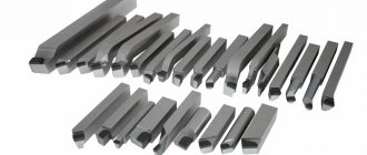
Feed movement during turning.
You probably already understood about the feed movement. YES this is the movement of the cutting tool which is fixed in the tool holder (for this sketch). The attachment of the incisors may be different, but more on that later.