Scope of application and features
Processing materials on a lathe involves securing a cylindrical workpiece into a three-jaw chuck. Due to the perpendicular feed of the cutting tool, the specified thickness of the metal is removed. All this allows you to grind the workpiece to the required size.
When performing certain jobs, simply fixing the workpiece in the chuck is not enough. To ensure safety, obtain the required cleanliness and accuracy, additional support of the part by the tailstock is required.
In what cases is it necessary to use a rotating center:
- The length of the workpiece is 5 times the diameter.
- Turning of heavy parts at high speeds (high speed and feed).
- Large thickness of chips removed.
- When finishing will take place on a grinding machine.
Features and benefits of using centers:
- Long service life.
- Resistance to high loads.
- Possibility to increase processing speed.
- Improving equipment performance.
- Versatility - can be used on manual machines and CNC equipment.
- High quality parts.
You might also be wondering how to properly mount a DRO on a lathe?
The disadvantages of the device include radial runout. If, according to technical requirements, this error is unacceptable, finishing is practiced using a fixed center in gentle modes.
Methods for installing workpieces on lathes
Installation and fastening of the workpiece on lathes is carried out depending on the shape, size and accuracy of the part [1]. The most commonly used installation methods are discussed below.
Installation in centers is often used for shafts, drums, cylinders, as well as workpieces mounted on mandrels. Small and medium-weight workpieces are mounted on solid thrust centers with a drive clamp, and a half-center is used to trim the end from the tailstock side (Fig. 1.2, a).
The driving clamp is used to transmit rotational motion from the machine spindle to the workpiece. A clamp with a manual clamp is put on the workpiece, secured with a screw, and then the workpiece with the clamp is installed in the centers of the machine. When the machine is turned on, the workpiece through the drive faceplate and clamp receives rotation from the spindle. When processing at high speeds, the rear centers are rotating; the installation accuracy in this case is lower. Blanks with holes are installed on the centers of the increased diameter
meters with the top of the cone cut off (fungal centers). In Fig. 1.2, b the rear center is fungal rotating, the front center is grooved (triangular or multi-toothed), which allows you to completely process a smooth shaft
Rice. 1.2. Installation of workpieces in the centers: a - on a solid thrust center with a drive clamp and a rear half-center; b - on the rear fungal rotating center and the front grooved center
or a cylinder along the outer surface and trim both ends of the workpiece, since processing is carried out without a leash.
Installation in the centers using a movable rest is used when processing non-rigid workpieces (Fig. 1.3). Steady rest is a support for reducing the deflection of long parts (at l
> 12d). The mounting surface under the steady rest is subject to high requirements in terms of total deviations and tolerances of the shape and location of surfaces.
Rice. 1.3. Installation in centers using a movable steady rest
The installation in the chuck and on a fixed steady rest is used to process the hole and end of the workpiece, as well as the section of the workpiece located between the steady rest and the chuck (Fig. 1.4).
When installed in chucks, workpieces of short length are processed. The greatest rigidity is ensured when the workpiece is attached to the outer or inner surface of the rim, the least when attached to the hub (Fig. 1.5).
and on a stationary rest
a) b)
Rice. 1.5. Installation in a three-jaw chuck: a - based on the outer diameter without resting on the end; b - end-based clamping
Workpieces with a hole with high requirements for the location of bases and machined surfaces are installed on end or center mandrels. The mandrels used are smooth with a gap (Fig. 1.6, a), conical (Fig. 1.6, b), collet (Fig. 1.6, c), with interference (Fig. 1.6, d), etc.
Price
| Type | Lathe | Type of work | Landing | Price, rubles |
| Fixed | JET | MK-3 | 500 | |
| Rotating | JET | MK-2 | 1800 | |
| Rotating | JET | MK-5 | 3000 | |
| Rotating | JET | for medium work | MK-3 | 2000 |
| Rotating | JET | for light work | MK-2 | 2800 |
| Rotating | JET | for heavy work | MK-5 | 3000 |
| Rotating | Tekhosnastka-S BT-5592 | for processing parts with center holes | A-1-3-N | 2050 |
| Rotating | Tekhosnastka-S BT-5598 | for processing parts with center holes | A-1-6-U | 11500 |
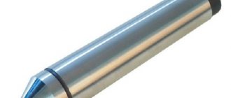
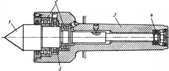
Design of rotating centers
The rotating center consists of a shaft and a conical tip. It is the working part that fixes the part. Rotation is ensured by a built-in ball bearing. It increases the efficiency of equipment, reduces friction and heating.
The standard tip angle is 60º. Such equipment is used in most cases when processing is carried out in standard modes. To work with heavy parts, a center with a tip angle of 90º is required.
The diameter of the tapered shank may vary depending on the tool model. To install the device in the tailstock, you will need a Morse taper 5.
Plasma cutting of metal
metal plasma cutting services .
in detail »
To estimate the cost and timing of the work, you must send: sketches, sample photos, drawings in any format to the email: [email protected] or click on the banner “calculate the cost of the order” In the letter, be sure to indicate: 1. Number of parts. 2. Material.
The mail is being tracked promptly and a response will be given shortly.
FAQ.
1. Do you have the material?
- The material is varied, steel, from ordinary carbon to alloyed, brass, copper, bronze, textolite, caprolon, ebonite, etc. By agreement, we will find unique grades of steels and alloys.
2. Do you take single orders?
- We take orders from the 1st unit. Minimum order 2000 rub.
3. What are the prices and how much does it cost to make a part?
- Prices range from 300-800 rubles/hour of machine time, depending on the order volume and complexity. A correct assessment can be given after studying the drawing, sketch or provided sample of the product sent by email. For urgency, the extra charge is from 20 to 50%, depending on the volume and degree of urgency.
4. What are the production times?
- Production time is from 2 days depending on the volume of the order.
Varieties
In turning, several types of rotating center are used. According to their purpose, equipment is divided into two types:
- Thrust center - the pointed tip rests against the end of the part. You must first make a centering hole.
- Fungal - has a tip of a larger diameter with a truncated cone. Used for fixing parts with an internal hole (pipes, hollow shafts).
By design:
- With permanent roller (type A).
- With replaceable nozzle (type B).
The use of type B allows you to use one device for processing products with different dimensions. Removable attachments make it easier for the cutter to approach the workpiece. Such equipment is often used when turning shaped parts.
Centers for lathes are made of high-strength alloy steel. Depending on the complexity of the process, they can be regular or enhanced. The latter are used when working with heavy products. Reinforced is durable and resistant to high loads.
Specifics of operation
Before starting work, the turner must take into account runout errors. It occurs due to wear of the bearings or tip, or insufficiently rigid fixation. If the requirements do not allow such an error, it is better to use other equipment.
What nuances need to be taken into account when processing in centers:
- The axes of the spindle and center must coincide, otherwise there will be processing errors. When turning parts with a high accuracy class, allowances must be left for finishing.
- The clamping force should securely fix the workpiece, but not interfere with its rotation.
- When working at high speeds, lubricant must be used to reduce tip wear.
Important!
The runout of the rotating center leads to radial runout of the part relative to the axis. Further processing of the same workpiece on another machine may lead to misalignment.
If strong runout is detected, the conical tip must be ground with a special tool, which is attached to the tool holder. After checking with a template, if the result is satisfactory, you can begin metalworking.
Important!
When turning at high speeds, the center tip wears out and the center hole breaks. To extend the life of the equipment, the tip is treated with a protective lubricant.
Rules for installing, aligning and securing workpieces and tools on a lathe.
Installation on centers
most often used for shafts, drums, cylinders, as well as various workpieces mounted on mandrels. Small and medium-weight workpieces are mounted on solid thrust centers.
When cutting the end of the workpiece from the tailstock side, use a half-center. When processing at high cutting speeds, rear centers are performed rotating (weight of parts up to 20 tons). The installation accuracy on such centers is lower than on solid ones (radial runout is allowed up to 0.007 and 0.015 mm, respectively, for centers of increased and normal accuracy). Blanks with a hole are placed on centers of increased diameter with the top of the cone cut off (fungal centers).
The use of a grooved center (triangular or multi-toothed) allows you to completely process a smooth shaft or cylinder along the outer surface and trim both ends of the workpiece, since processing is carried out without a driver. However, installation on grooved centers does not provide high accuracy (radial runout up to 0.5 mm); it allows only one-time use of the base due to its damage during the first installation.
Small-diameter workpieces are mounted on reverse centers using conical chamfers on the outer surface. Transmission of torque during finishing of such workpieces is possible without a driver. Processing of cones by the method of displacement of the tailstock is carried out with installation on ball centers.
Installation on a floating front center with the workpiece based on the end provides high axial dimensional accuracy (with the method of automatically obtaining dimensions). To reduce vibration, the systems provide for locking the center manually using screw 1 or automatically when the center is jammed by the plungers
Installation on plugs is carried out without alignment with an accuracy of 0.03-0.10 mm, on welded crosses - with an accuracy of 0.2 mm. When installing a workpiece on adjustable crosspieces, the radial runout and position of the part in the horizontal and vertical planes are controlled with an accuracy of 0.5 mm.
Installation in the chuck and on the rear center
used in the case of processing workpieces of large diameter and length, in the absence of a center hole on the side of the headstock. Installation accuracy in self-centering chucks is 0.05-0.10 mm; when using a four-jaw chuck, the installation is performed by aligning the position of the workpiece on the chuck side in height and runout with an accuracy of 0.05 mm.
Installation in a chuck and on a fixed rest
used for processing the hole and end of the workpiece, as well as the area of the workpiece located between the steady rest and the chuck.
When processing heavy workpieces, open-type steady rests are used, in other cases - closed type. Special belts are machined under the steady rests. The workpieces are installed by checking the position in the horizontal and vertical planes and the runout with an accuracy of 0.03 - 0.05 mm. Workpieces are installed in special chucks without alignment
Installation on centers using a movable steady rest
used when processing non-rigid workpieces
When installed in cartridges
Process workpieces of short length. The greatest rigidity of the system is ensured when the workpiece is attached to the outer or inner surface of the rim (crown), and the least when attached to the hub. Installation in self-centering chucks is carried out without alignment with an accuracy of 0.1 mm; in a split bushing or non-hardened cams - 0.03 mm; in four-jaw chucks with alignment along the outer diameter and end - with an accuracy of 0.05 mm.
Workpieces with holes with high requirements for the location of bases and machined surfaces are installed on end or center mandrels
.
Parts of complex shape (levers, body parts) when processed on lathes are mounted on a faceplate
. The correct installation is checked by aligning the position of the cylindrical surfaces, the end and the parting plane. To reduce vibration, a balancer is used.
Installation on a square
used when processing housing parts, bearings, etc. The workpiece is fixed in special fixtures without alignment (installation accuracy 0.1 mm) or on a universal square with alignment to markings or previously processed surfaces and parting planes - installation accuracy 0.5 mm. Fastening on a square is often used when processing a system of coaxial holes of different diameters in body parts on CNC machines. By shifting the cutter along the radius, you can obtain the specified hole sizes. This is more difficult to do on CNC boring machines.
In the absence of boring machines, heavy unbalanced body parts are processed on lathes with the workpiece mounted on a support
; the tool is mounted in the spindle with additional support on the tailstock.
When aligning cylindrical workpieces installed in three- and four-jaw chucks
, check the runout of the workpiece (for a long length, the runout is checked at the chuck and at the free end). The control tool is fixed on the support or on the machine bed. In the second method, to speed up installation, the intersection point of the marks is cored, the workpiece is pressed with the center, and then the cams are carefully brought in.
To align the position of the composite workpieces, mark the position of the diametrical plane, and then use an indicator to check the position of the joint (achieve a horizontal position of the joint plane and align it with the axis of rotation).
When installed in a chuck and steady rest
control the runout of the workpiece at the chuck. The correct position in the vertical and horizontal planes is assessed by the gap between the thicknesser needle and the surface of the workpiece using indicators.