Description of Laval nozzle:
A Laval nozzle is a gas channel of a special profile that accelerates the gas flow passing through it to supersonic speeds. The nozzle is a channel that tapers in the middle. In the simplest case, such a nozzle may consist of a pair of truncated cones connected by narrow ends.
The phenomenon of gas acceleration to supersonic speeds in a Laval nozzle was discovered at the end of the 19th century. experimentally. The nozzle was first proposed in 1890 by the Swedish inventor Gustaf de Laval for steam turbines, and is therefore named after its inventor. Then in 1913, R. Goddard filed an invention application for the use of a Laval nozzle in a two-stage solid propellant rocket. The Laval nozzle is now widely used on some types of steam turbines, rocket engines and supersonic jet aircraft engines.
Later, this phenomenon - the acceleration of gas to supersonic speeds - found a theoretical explanation within the framework of gas dynamics and corresponding gas-dynamic calculations.
New in blogs
A Laval nozzle is a gas channel of a special profile that accelerates the gas flow passing through it to supersonic speeds. Widely used on some types of steam turbines and is an important part of modern rocket engines and supersonic jet aircraft engines /Vicki/.The effect of gas acceleration to supersonic speeds in a Laval nozzle was discovered at the end of the 19th century. in an experimental way. Later, this phenomenon found a theoretical explanation within the framework of gas dynamics (for example, M.A. Lavrentyev, B.V. Shabat “Problems of hydrodynamics and their mathematical models”, “Science”, Moscow, 1973, chapter 4, paragraph 17 “Problem of nozzle", page 149).
The Laval nozzle consists of a tapering part, a neck and a diverging part:
The movement of gas in the tapering part of the nozzle occurs at a speed less than the speed of sound for a given gas; in the neck it is carried out at the speed of sound, and in the diverging part of the nozzle it exceeds the speed of sound (see diagram, where M is the Mach number, defined as M=v/u, v is the gas speed, u is the speed of sound in the gas):
From the equation of state of an ideal gas and the energy balance in the gas flow, a formula is derived for calculating the linear velocity of gas outflow from the Laval nozzle:
where: ve is the gas velocity at the nozzle exit, m/s, T is the absolute gas temperature at the inlet, R is the universal gas constant, R=8314.5 J/(kilomol•K), M is the molar mass of the gas, kg/ kilomol, k - adiabatic exponent, k=cp/cv, cp - specific heat capacity at constant pressure, J/(kilomol•K), cv - specific heat capacity at constant volume, J/(kilomol•K), pe - absolute gas pressure at the nozzle exit, Pa p - absolute gas pressure at the nozzle inlet, Pa
The Laval nozzle is the main element of any jet engine for creating jet thrust - a force resulting from the interaction of the propulsion system with a stream of gas flowing from the nozzle, which has kinetic energy. The origin of jet thrust is based on the law of conservation of momentum.
The principle of operation of a rocket engine is based on the fact that engine thrust is created due to the reaction of gases ejected from the engine nozzle under the influence of internal forces. To the mass consisting of the mass of the rocket engine and the mass of the gases emitted from it, the theorem from theoretical mechanics about the movement of the center of mass of the system is applicable, according to which “the center of mass of the system moves as a material point, the mass of which is equal to the mass of the entire system and to which external forces are applied, acting on the system." From this theorem follows the law of conservation of motion of the center of mass, which does not change its position in the absence of external forces. This means that if the element of mass dm of the gas leaving the combustion chamber has a speed ve relative to the rocket engine, then the remaining mass of the engine m receives a speed increment in the opposite direction mdve = vedm (A.V. Yaskin THEORY OF ROCKET ENGINES, textbook).
Consequently, the reactive force (thrust) R is equal to the product of the fuel mass flow dm/dt by the speed ve of the outflow of its combustion products and is directed in the opposite direction to the vector of this speed R = - ve dm/dt.
The rate of exhaustion of combustion products (working fluid) is determined by the physical and chemical properties of the fuel components and the design features of the Laval nozzle and the entire engine.
In gas dynamics, a formula is derived for determining the specific impulse of a Laval nozzle with the nozzle exit area A, which, along with the gas pressure at the nozzle exit pe, includes the ambient pressure p0:
where is the second mass flow rate of gas through the nozzle. From this formula it follows that, due to external atmospheric pressure, the engine thrust depends on the ratio of the ambient pressure and the flow pressure in the outlet section of the nozzle.
The geometry of the nozzle plays an important role: a nozzle made with underexpansion creates less thrust than the design nozzle, and a nozzle with overexpansion creates a negative thrust component in the overexpanded section, the value of which is subtracted from the thrust created by the design nozzle. When the nozzle operates with underexpansion, as estimates show, the thrust losses are significantly greater than when the nozzle operates with overexpansion. Due to the unchanged geometry of the nozzle, the vast majority of cameras operate in off-design, or average, mode as the rocket takes off. The use of discardable pads or an expanding part of the nozzle with variable geometry partially solves this problem. However, the geometry of the tapering part of the nozzle is difficult to change during engine operation. It is in the tapering part of the nozzle that most nonlinear processes occur that affect the amount of jet thrust. The fact is that the formula for the speed of gas outflow from a Laval nozzle is obtained from the condition that the gas is ideal and the speeds of subsonic and supersonic flows “stick together” continuously both in magnitude and in direction. In this case, the tangent derivatives on the transition line will be continuous, which leads to different options for deducing the transition line through the speed of sound in the nozzle. To date, there is no complete solution to the nozzle problem. For example, A.A. Nikolsky and G.I. Taganov established that the transition line should be strictly convex. F.I. Frankl and others prove the impossibility of flows with local supersonic zones without a speed break. Such local discontinuities can serve as sources of turbulent flows. The reason for these problems is due to the fact that the speed of sound propagation in a moving stream of high-temperature gas is a function of many parameters.
In a general sense, the speed of sound propagation is understood as the local speed of propagation of small disturbances relative to the moving gas at a given point in the flow. In gases and liquids, sound propagates in the form of volumetric compression-discharge waves and depends on the temperature of the propagation medium, composition, viscosity, thermal conductivity, impurities and their concentration, external electromagnetic fields, etc. In a flow of viscous gas with transverse shear, for example, intense energy dissipation occurs, leading to jumps in the speed of sound (S.S. Voronkov ON THE SPEED OF SOUND IN GASES):
And this leads to turbulence, which is what is observed in jet engines:
But, as you know, vortexes can both be beneficial and cause harm. At least at present, jet technology developers are trying to suppress (minimize) any turbulence that occurs in the Laval nozzle. It is a well-known fact that a Benard vortex is formed in a Ranque tube, the internal flow of which cools the air, which is contraindicated in jet technology. But: one thing is turbulence in a gas flow, carrying away the energy of the gas, and another thing is a flow of matter consisting of gas vortex clusters!
A certain model of a quasi-gas, in which the role of its constituent particles is played by organized and controlled structures, the speed of sound propagation in the environment of which will be determined by the parameters of these vortices themselves:
where: p and ρ are the pressure and density of vortex clusters.
An example of the generation of vortices of a higher order than atoms is given in the publication Gravitational Engine. This way of improving rocket technology has the prospect of designing a Laval nozzle with walls that are variable and controllable during flight, the role of which will be played by an electromagnetic field, which simultaneously performs another function - the role of a vortex flow accelerator.
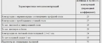
Do-it-yourself Laval nozzle – Metalist's Handbook
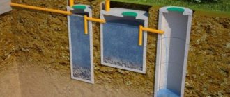
To produce affordable building materials, various types of equipment are used, including a foam generator for foam concrete.
Despite the ease of manufacture and low cost, the technical requirements for foam concrete blocks are strict.
To achieve high quality in the production of this building material, it is necessary to strictly comply with all technological standards.
Purpose of the foam generator
Currently, foam concrete is in demand in individual construction as an affordable and high-quality material. This is due to its high performance characteristics.
Low-rise residential buildings, garages, country houses and various outbuildings are erected from foam concrete.
Foam blocks do not burn and are not subject to shrinkage; they are sufficiently resistant to any atmospheric influences.
In winter, buildings made of foam concrete retain heat well; in summer, such rooms are not hot. You can produce foam concrete yourself using a homemade foam generator.
:
The practice of recent years shows that more and more people are striving to build a house or garage on their own. This approach has become widespread due to technical capabilities.
Equipment for the production of foam concrete can be purchased at an affordable price or made independently.
One of the main elements of the installation is a foam generator. This device is used to ensure that the concrete block is saturated with foam, thereby giving the block its characteristics.
Today on the construction equipment market you can find and buy a foam generator suitable for power.
However, you can make a foam generator for foam concrete with your own hands without significant financial costs, which will reduce construction costs.
The quality of the foam that is formed in homemade foam generators is exactly the same as in factory ones.
Once you become familiar with the operating principle of such a unit, you can draw your own drawings and begin manufacturing.
The foam generator consists of the following elements:
- shut-off and control equipment;
- chamber for forming the mixture;
- nozzle.
The specific design of the foam generator may undergo changes, but the principle of operation remains the same.
Operating principle
The main function of the foam generator is to ensure the supply of foam to the sand-cement mortar prepared in advance.
To produce foam concrete, an ordinary concrete mixer is used. Concrete is mixed in it for pouring foundations and walls or mortar for brickwork.
When, during the process of mixing the solution, a certain amount of foam gets into it, ordinary concrete turns into foam concrete.
All specialists are aware of the advantages and disadvantages of foam concrete. Today, this building material can be prepared directly on the site where a house, garage or other object is being built.
Foam Generator Structure
When starting to make a foam generator with your own hands, you need to optimize all the drawings and descriptions that catch your eye.
The fact is that many specialists, having become familiar with the operating principle of a foam generator, immediately apply the acquired knowledge, turning it into reality.
Schemes and drawings:
A clear demonstration of the operation of a foam generator can be seen at any car wash.
The foam, when mixed, fills a certain volume of the concrete block and thereby reduces its original density.
The simplest foam generator can be assembled from the following elements:
- foam solution supply pipe;
- compressed air supply pipe;
- mixing chamber;
- foam cartridge.
Factory-made foam concentrate is always available on the shelves in building materials stores.
If this is not possible, then the emulsion can be prepared by mixing gum rosin, caustic soda and bone wood glue. The cooking process is not complicated, but requires care.
After the homemade foaming agent is ready, you need to check its quality. The foam must have sufficient density and durability.
Assembly and connection
The main elements of a foam generator for the production of foam concrete are a mixing chamber and a foam cartridge. In this context, it is important to emphasize that behind these terms lie ordinary elements that are well known to masters.
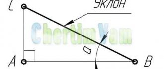
The mixing chamber is an ordinary pipe. The diameter of the pipe is selected depending on the power of the future generator. Two pipes are welded to the pipe.
:
The first is at the end, intended for air supply, the second is in the middle of the pipe at an angle of 90 degrees. A foaming agent solution is supplied through it. A shut-off valve must be installed on each branch pipe.
Foam generators for factory-made foam concrete are equipped with two valves - a shut-off valve and an adjustment valve.
The practice of recent years shows that for small production volumes, when it is necessary to produce foam blocks for the construction of a garage or country house, one shut-off valve is sufficient.
A pipe is welded to the second end of the mixing chamber, which serves as a foam cartridge. If possible, the inner surface of the pipe is treated in the shape of a funnel.
This is done to reduce the flow rate of the foaming agent and air mixture to ensure foam formation.
Some nuances
When the mixing chamber and foam cartridge are connected, an element called a Laval nozzle or another device, a nozzle, is fixed between them.
These elements are designed to increase the flow rate of the mixture during the transition from the chamber to the foam cartridge. It is in the foam cartridge that the final formation of foam occurs.
To make the process more efficient, the flow of the foaming agent is “broken” against a special filter.
In homemade foam generators, kitchen metal mesh, which is sold in every hardware store, is used as such a filter.
Building a foam generator with your own hands to produce foam concrete is not a difficult task. The main thing here is to understand the principle of operation of the generator.
:
A technically more difficult task is to correctly connect the foam generator to the main equipment.
Currently, the designs of concrete mixers that are used for the production of blocks can be found in a variety of ways.
Before assembling the foam generator, it is necessary to determine all the installation elements that are used when connecting hoses and pipes.
Sandblasting nozzle: rules for choosing and making it yourself
The nozzle, which is used to equip a sandblasting machine, is the most important design element of such a device.
Only a correctly selected nozzle will allow you to most effectively use the sandblaster for its intended purpose: to clean various surfaces from dirt, old coatings, traces of corrosion, degrease them and prepare them for further processing.
For each application, you can select a nozzle of a certain diameter, depending on the fraction of sand used
The tasks that a sandblasting nozzle solves are to compress and accelerate to the required speed a mixture consisting of air and abrasive material, as well as to form a working spot and saturate it with abrasive acting on the surface of the workpiece.
Depending on the size of the surface to be sandblasted, different types of holes can be made in the nozzles.
Thus, for processing narrow surfaces, nozzles with the same diameter along the entire length are used, and for cleaning large surfaces, products are used, the holes in which have larger diameters at the inlet and outlet (Venturi type, developed in the middle of the last century).
The essence of sandblasting
Sandblasting involves exposing various surfaces to an abrasive material. Sand, shot, silicon carbide, small glass beads, etc. are used as the latter.
Sandblasting is a mechanical action on the surface of small solid particles
Before processing begins, the abrasive is placed in a sealed hopper. Air coming from a separate compressor is supplied through the main hose of the device under high pressure.
Passing by the opening of the intake hose, the air flow creates a vacuum in it, which facilitates the suction of abrasive into the main hose.
The air, already mixed with abrasive, is supplied to the gun, the main element of which is a sandblasting nozzle, through which the abrasive mixture is supplied to the surface being treated.
Layout of the sandblasting area
As mentioned above, various types of abrasives can be used to perform sandblasting. The choice here depends on the type of surface that needs to be cleaned.
Thus, treatment using sand is effective in cases where it is necessary to remove a layer of old paint from a concrete surface, clean brick walls from cement residues, and prepare metal parts for further painting.
Abrasives such as plastic or wheat starch are successfully used in the shipbuilding, automotive and aircraft manufacturing industries, with their help they effectively remove old coatings from composite materials.
Design features of a nozzle for a sandblasting machine
The main parameters of the nozzle installed on the sandblasting machine are:
- diameter and type of hole;
- length;
- manufacturing material.
Abrasive blasting nozzles of various configurations
The diameter of the hole in the nozzle, which is fixed on the sandblasting machine using a special nozzle holder, is selected depending on the performance the device should have.
The performance of any sandblasting machine - both serial and home-made - depends on the power of the jet or the volume of air that the nozzle is able to pass per unit time.
The power of the jet generated by the nozzle is directly proportional to the volume of air that passes through it per unit time. Accordingly, in order to increase the power of the sandblasting machine, it is necessary to make a hole of a larger diameter in its nozzle.
If a nozzle whose diameter corresponds to 6 mm (1/4 inch) has a power equal to 100%, then products with holes of larger diameters will differ in the following value of this parameter:
- 8 mm (5/16 inch) – 157%;
- 9.5 mm (3/8 inch) – 220%;
- 11 mm (7/16 inch) – 320%;
- 12.5 mm (1/2 inch) – 400%.
The reality of using cavitation for heating
There are articles on the Internet about rotary-type vortex generators, the principle of which is to create areas of cavitation when an impeller of a specific shape rotates in a liquid. Is this solution viable?
Let's start with theoretical calculations.
In this case, we spend electricity to operate the electric motor (average efficiency - 88%), and partially spend the resulting mechanical energy on friction in the seals of the cavitation pump, and partially on heating the liquid due to cavitation.
That is, in any case, only part of the wasted electricity will be converted into heat.
But if you remember that the efficiency of a conventional heating element is from 95 to 97 percent, it becomes clear that there will be no miracle: a much more expensive and complex vortex pump will be less efficient than a simple nichrome spiral .
Specific impulse
Thrust is the force that moves a rocket through the air or space. Thrust is generated by a rocket's propulsion system by applying Newton's third law of motion: "For every action there is an equal and opposite reaction." The gas or working fluid is accelerated from the rear of the rocket engine nozzle, and the rocket is accelerated in the opposite direction. The thrust of a rocket engine nozzle can be defined as:
F = m ˙ v e + ( p e - p o ) A e = m ˙ [ v e + ( p e - p o m ˙ ) A e ] , F & = > v _ > + \ left (p _ > - p _ > \ right) A _ > \\ [2pt] & = > \ left , \ end
>>
and for injectors with
by ideal extension (
p
e =
p
o ) this reduces to:
F = m ˙ v eq . >v_>.>
Specific impulse is the ratio of the generated thrust to the weight consumption of gunpowder. It is a measure of the fuel efficiency of a rocket engine. In English engineering units it can be obtained as i sr >>
i sp = F m ˙ g o = m ˙ v eq m ˙ g o = v eq g o , > = > g _ >>> = > v_ >> > g _ >>> = >> >> > ,>
| F | total thrust of the rocket engine (N) |
| m ˙ >> , | gas mass flow (kg/s) |
| v e >> , | gas velocity at nozzle exit (m/s) |
| n e >> , | gas pressure at the nozzle exit (Pa) |
| p o >> , | external ambient or free flow, pressure (Pa) |
| A e >> , | nozzle exhaust area (m²) |
| v eq >> , | equivalent (or effective) gas velocity at nozzle exit (m/s) |
| I am born >> , | specific impulse(s) |
| g about >> , | standard gravity (at sea level on Earth); approximately 9.807 m/s2 |
In some cases, when equal to , the formula takes the form p e >>
p o >>
i sp = F m ˙ g o = m ˙ v e m ˙ g o = v e g o > = > \, g _ >>> = > \, v _ >> > \, g _ >> > = >> >>>>
In cases where this may not be the case, since for a rocket the nozzle is proportional to , it is possible to define a constant that is the vacuum for any given engine, thus: p e >>
m ˙ >> i sp, vac >>
i sp, vac = 1 g o ( v e + p e A e m ˙ ) , > = >>> \ left (v _ > + > A _ >> >> \ right),>
F = i sp, vac g o m ˙ — A e p o , > \, g _ > > — A _ > p _ >, >
which is simply the vacuum thrust minus the ambient atmospheric pressure force acting on the exit plane.
Essentially, for rocket nozzles, the ambient pressure acting on the engine is canceled out except at the rocket engine exit plane in the reverse direction, while the exhaust jet produces forward thrust.
- underexpanded
- surrounding
- overextended
- greatly overextended.