Wave reducer device
The wave gearbox consists of three main parts: a wave generator, a rigid wheel and a flexible wheel. The wave generator in the most common version is made in the form of a ball bearing with thin flexible walls. It is installed on an elliptical bushing, and itself takes the shape of an ellipse. The assembly of these two parts is the wave generator. The flexible wheel is a part specific to the wave gearbox. It is a thin-walled gear with an external tooth. The main working surface of this wheel has the shape of a cylinder. The material and thickness of the flexible wheel are selected so that it can constantly experience elastic deformation without losing its properties. The design of the rigid wheel is simpler than other parts of the wave gearbox. This is a regular gear with an internal tooth. Its dimensions are selected to provide sufficiently high rigidity under operating loads.
| wave generator | flexible wheel | hard wheel |
When assembling a wave gearbox, a flexible wheel is installed on the wave generator, as a result of which it also takes on an elliptical shape. Next, a rigid wheel is installed on the flexible wheel. Since the flexible wheel took on an elliptical shape during the assembly process, its engagement with the rigid wheel occurs only in two areas. They are located along the semi-major axis of the wave generator and in total occupy about 40% of the circumference. Outside these areas, the teeth of the rigid and flexible wheels do not engage. A flexible wheel has fewer teeth than a rigid wheel. Most often, this difference is 2 teeth, but there are other design options for wave gearboxes where this difference is larger.
Wave reducers
Wave gear motors
Wave gearboxes are built using a flexible wheel (flexible ring gear) that is installed in the wave generator.
The technical complexity of the flexible wheel, through which significant force is transmitted, is high, so the wave transmission was patented only in 1958. It immediately found application in systems where high torque is not required, but smooth movement is required. The main prospects for using wave gearboxes are industrial manipulators, assembly robots, and CNC machines. The gear drive circuit of the manipulators is simpler and more reliable than the hydraulic one. In manipulators, it is appropriate to use so-called wave gear motors, where the electric motor is combined in one housing with gears. This solution provides material savings and lower equipment costs while maintaining technical characteristics. A version with an oil-filled crankcase is possible, when it is used not only for lubrication, but also for cooling gears and windings.
Wave geared motors are used where very low rotation speed on the output shaft is required. They also ensure the alignment of the input and output shafts, which is very convenient when designing machine tools. At the same time, the wave circuit makes it possible to achieve a gear ratio of 1:100 or 1:300 with the minimum possible number of parts. This is not available for other types of gearboxes, including planetary ones. The large gear ratio is ideal for high-speed electric motors. Such a drive shifts extraneous noise and vibration to a higher frequency region, from which it is easier to make noise and vibration insulation.
The number of gear ratios for wave gearboxes is limited to the range of 80-400. If the gear ratio is made less than 80, then the deformation of the flexible wheel will be too great per revolution, and it will not last long. If, on the contrary, the gear ratio is made too large, then slippage of the wheel teeth is possible if their diameter is very large. The lower limit can be lowered to less than 80 if plastic wheels are used instead of metal flexible wheels.
Operating principle of wave gearboxes
If in a conventional gearbox, for example, a classic cylindrical gearbox, all the gear teeth work per cycle, then in a wave gearbox there are only two or three teeth of the impeller. The wave generator disengages the teeth of the flexible gear from engaging the rim. For a full revolution of the wave generator, the flexible wheel will rotate 1/50 with a number of teeth of 200 and meshing of 4 teeth. Thus, even a very compact wave gearbox can easily be made with a gear ratio of 1:100. Efficiency - 90%. These are the qualities needed to drive industrial manipulators. The wave gearbox contains three main elements:
- flexible wheel;
- hard wheel;
- wave generator
The main disadvantage of wave transmission is the fragility of the flexible element. It must complete one bending cycle per revolution of the wheel. A special design made of composite materials is used for the flexible element. The ring gear is made from materials with high wear resistance - metal, special polymers.
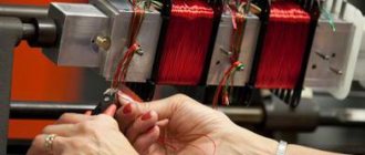
Flexible base - made of metal-polymer composite. It can withstand millions of revolutions. The use of unified models makes it easy to select spare parts and reduce equipment downtime for repairs.
The flexible wheel is the most difficult element to design. Computer-aided design systems are used because it is necessary to solve two opposing problems at once: to ensure resistance to repeated bending and to ensure sufficient strength and hardness of the gear teeth.
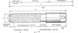
Wave generator
The deformation of the flexible gear rim is provided by a wave generator in the form of two blades with a roller sliding device along the inner surface of the rim. The roller wave generator is simple, reliable and has a minimum number of elements. Various schemes are possible in the form of a one-, two- and three-wave generator. To reduce losses in wave transmission, several technological methods are used:
- increasing the diameter of the gear rims;
- reducing the size of the teeth so that 30-70 or more teeth are involved in meshing in one wave;
- reducing the degree of deformation of the crown;
- increasing the contact area of the rollers with the crown (increasing the width of the flexible crown);
- Partial filling of the gearbox with oil.
The wave generator ensures complete insertion of the teeth into the meshing zone and complete disengagement of the teeth in half a turn (for a two-wave circuit). The two-wave circuit provides the advantage of a symmetrical design of the wave generator, as a result of which the use of counterweights is not required, and the gearbox is able to operate at high rotation speeds. In commercially produced wave gearboxes, several design options for the wave generator are used.
- Cam generator.
- Fixed wave generator.
- Disk generators.
The disk circuit does not require a special bearing. It is the most common. The two-wave generator has three disks. It does not require special counterweights. Structurally, the reduction of teeth required for a wave gearbox does not lead to a decrease in the permissible torque on the output shaft. It is due to the deformation of the flexible wheel that 10-40 times more teeth are involved in meshing than for a rigid gear of the same diameter. The number of teeth involved in meshing increases with the application of load. For example, for standard 200-tooth flexible wheels, up to 40 teeth are engaged on each side of the wave generated by the generator, so that the total number increases to 80. In a conventional 200-tooth gear, only 2-4 teeth are in mesh at a time.
Thanks to these qualities, wave gearboxes are widely used in production. You can order any models from our company.
Principle of operation
As the wave generator rotates, the teeth of the flexible and rigid wheels alternately begin to engage. As a result, the teeth meshing areas begin to shift in the same direction in which the wave generator rotates. As soon as the wave generator makes a full revolution, the flexible and rigid wheels will be shifted relative to each other by the same 2 teeth, which make up the difference in the number of teeth between these wheels. This means that the flexible and rigid wheels turned relative to each other at a speed significantly less than the speed at which the wave generator rotated. The wave generator, rotating quite quickly, allows you to obtain a relatively slow rotation of a flexible wheel relative to a rigid one - that is, the mechanism works like a gearbox. The reduction coefficient of such a wave gearbox depends on the difference in teeth between the flexible and rigid ring, as well as on the number of teeth on the rigid ring.
Wave gear [edit | edit code]
Operating principle [edit | edit code ]
It consists of a rigid stationary element - a gear with internal teeth, stationary relative to the gear housing; flexible element - a thin-walled elastic gear with external teeth connected to the output shaft; wave generator - a cam, eccentric or other mechanism that stretches a flexible element until pairs of engagement with a fixed element are formed at two (or more) points. The number of teeth of the flexible wheel is slightly less than the number of teeth of the fixed element. The number of deformation waves is equal to the number of protrusions on the generator. At the tops of the waves, the teeth of the flexible wheel fully engage with the teeth of the rigid one, and at the troughs of the waves they completely disengage. The linear speed of the deformation waves corresponds to the speed of the tops of the protrusions on the generator, that is, in the flexible element there are traveling waves with a known linear speed. The difference in the numbers of teeth of a rigid and flexible wheel is usually equal (less often a multiple) to the number of deformation waves.
Inclusion options
When a wave gearbox is used as shown above, the wave generator is used as the input, the flexible wheel is the output, and the rigid wheel remains stationary. The wave gearbox can be used in another way, if you fix not a rigid wheel, but a wave generator or a flexible wheel; In this case, the input and output can be from the two remaining elements of the gearbox. With various switching options, wave transmission can be used both to reduce the speed and to increase it. The gear ratio will also change. The direction of rotation of the output element relative to the input element may also change.
In a wave gearbox, all three elements can be rotated. The gearbox will have two inputs and one output or one input and two outputs. This allows the wave gearbox to be used as a differential, adding up the rotation speeds on different shafts, or splitting the rotation into two different shafts.
Options for compact wave gearboxes
During the time that has passed since the invention of the wave gearbox, many variants of its design have been invented. And the option when an elliptical ball bearing is used as a wave generator does not exhaust all possible design options. There are other options. For example, a wave generator can be made in the form of a rocker with rollers at its ends. Or in the form of planetary gears mounted on the carrier, which mesh with teeth made on the inside of the flexible wheel. In addition, the wave generator can be made in the form of a part of a more complex shape, creating 3 or 4 engagement zones on a flexible ring (instead of two zones in the simplest case).
The flexible wheel can also have different shapes. In practice, three forms are most often found: “pan”, “hat” and cylinder. The differences between them lie in ease of use.
| Flexible pan wheel | Flexible cylinder wheel | Flexible hat wheel |
The main differences of the wave gearbox
- Large gear ratio for single-stage gearboxes: up to 320:1 in series-produced products
- A large number of teeth that are in simultaneous mesh
- High accuracy
- Large load moment per unit volume or per unit mass
- No small gear ratios (less than 30:1)
- Simple design
- High reliability
- Simple transfer of rotation to another medium
- Hollow shaft
- Torsional rigidity is limited
- Short axial length
Practical advantages of wave gearboxes
The distinctive features of wave gearboxes act as advantages in a number of industries that are currently highly developed. Examples include robotics (classical industrial robots, collaborative robots, and humanoid robots) and medical technology (surgical robots, medical scanning units, and exoskeletons). The short length along the axis, the ability to obtain high torque in compact dimensions, as well as the hollow shaft allow for compact dimensions of all parts of the robot, and the high precision of the gearboxes allows for good accuracy of the entire robot.
In other industries, where finished products must operate in aggressive environments (for example, vacuum, radioactive radiation, particularly high or very low temperatures, wave gearboxes are also often used. Here, a high specific torque is in demand, allowing for a compact design, the ability to simply transfer rotation to an aggressive environment without additional seals and good reliability indicators due to the simple design.
Application [ edit | edit code ]
Wave transmissions are used in aviation and space technology, in industrial robots and manipulators, in drives of lifting machines, machine tools, conveyors, etc.
There are sealed wave transmissions that transmit rotation in a sealed cavity located in a chemically aggressive or radioactive environment, or in a deep vacuum, and there are also structures that serve as drives for sealed valves.
Used on the lunar vehicle used during the Apollo 15, Apollo 16 and Apollo 17 lunar missions in the early 1970s.