We recommend purchasing:
Installations for automatic welding of longitudinal seams of shells - in stock!
High performance, convenience, ease of operation and reliability in operation.
Welding screens and protective curtains are in stock!
Radiation protection when welding and cutting. Big choice. Delivery throughout Russia!
General information about cones
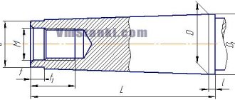
A conical surface is characterized by the following parameters (Fig. 4.31): smaller d and larger D diameters and the distance l between the planes in which circles with diameters D and d are located. Angle a is called the angle of inclination of the cone, and angle 2α is called the angle of the cone.
The ratio K= (D - d)/l is called taper and is usually indicated with a division sign (for example, 1:20 or 1:50), and in some cases with a decimal fraction (for example, 0.05 or 0.02).
The ratio Y= (D - d)/(2l) = tanα is called the slope.
Methods for processing conical surfaces
When processing shafts, transitions between surfaces that have a conical shape are often encountered. If the length of the cone does not exceed 50 mm, then it can be processed by cutting in with a wide cutter. The angle of inclination of the cutting edge of the cutter in plan must correspond to the angle of inclination of the cone on the machined part. The cutter is given a transverse feed movement.
To reduce the distortion of the generatrix of the conical surface and reduce the deviation of the angle of inclination of the cone, it is necessary to install the cutting edge of the cutter along the axis of rotation of the workpiece.
It should be taken into account that when processing a cone with a cutter with a cutting edge more than 15 mm long, vibrations may occur, the higher the level of which, the longer the length of the workpiece, the smaller its diameter, the smaller the angle of inclination of the cone, the closer the cone is to the middle of the part, the greater the overhang cutter and less strength of its fastening. As a result of vibrations, marks appear on the treated surface and its quality deteriorates. When processing hard parts with a wide cutter, there may be no vibrations, but the cutter may shift under the influence of the radial component of the cutting force, which leads to a violation of the cutter’s adjustment to the required angle of inclination. (The offset of the cutter depends on the processing mode and the direction of feed movement.)
Conical surfaces with large slopes can be processed by turning the upper slide of the support with the tool holder (Fig. 4.32) at an angle α equal to the angle of inclination of the cone being processed. The cutter is fed manually (using the handle for moving the upper slide), which is a disadvantage of this method, since the unevenness of the manual feed leads to an increase in the roughness of the machined surface. Using this method, conical surfaces are processed, the length of which is commensurate with the stroke length of the upper slide.
A long conical surface with an angle α= 8… 10° can be machined when the tailstock is displaced (Fig. 4.33)
h = Lsinα.
At small angles sinα ≈ tanα
h≈L(Dd)/(2l),
where L is the distance between centers; D - larger diameter; d—smaller diameter; l is the distance between the planes.
If L = l, then h = (Dd)/2.
The tailstock displacement is determined by the scale marked on the end of the base plate on the flywheel side and the mark on the end of the tailstock housing. The scale division is usually 1 mm. If there is no scale on the base plate, the tailstock displacement is measured using a ruler attached to the base plate.
To ensure the same taper of a batch of parts processed by this method, it is necessary that the dimensions of the workpieces and their center holes have minor deviations. Since misalignment of machine centers causes wear on the center holes of the workpieces, it is recommended to pre-machin the conical surfaces, then correct the center holes and then perform final finishing. To reduce the breakdown of the center holes and the wear of the centers, it is advisable to make the latter with rounded tops.
Quite common is the processing of conical surfaces using copying devices. A plate 7 (Fig. 4.34, a) with a tracing ruler 6 is attached to the machine bed, along which a slider 4 moves, connected to the support 1 of the machine by a rod 2 using a clamp 5. To freely move the support in the transverse direction, it is necessary to disconnect the screw for the transverse feed movement. When the caliper 1 moves longitudinally, the cutter receives two movements: longitudinal from the caliper and transverse from the tracing ruler 6. The transverse movement depends on the angle of rotation of the tracing ruler 6 relative to the axis of rotation 5. The angle of rotation of the ruler is determined by the divisions on plate 7, fixing the ruler with bolts 8. The movement of the cutter feed to the cutting depth is carried out by the handle for moving the upper slide of the caliper. External conical surfaces are processed with through cutters.
Machining taper surfaces
In production, it is often necessary to process shafts that are structurally designed with conical transitions between the diameters of the journals. If the length of the conical surface is no more than 50 mm, it is ground with a wide cutter. In this case, the cutter must have a cutting edge inclination angle similar to the cone angle on the manufactured product. The feed movement with the cutter is transverse.
To reduce the deformation of the plane forming the cone and eliminate errors affecting the inclination angle of the cone, the cutting edge of the cutting tool is fixed along the axis of the workpiece. If the cutting edge of the cutter is longer than 15 mm, harmful vibrations occur during processing.
Vibrations increase under the following conditions:
- increasing the length of the workpiece;
- reducing the diameter of the workpiece;
- smaller cone slope angle;
- close distance of the cone to the center of the workpiece;
- increase in cutter overhang;
- weak fixation of the cutter in the normal position.
Exposure to harmful vibrations negatively affects the quality of processing. Traces, unevenness, and roughness appear on the surface. By using cutters with a wide cutting part, vibrations are avoided. In this case, the radially directed cutting force can disrupt the cutter settings, changing the slope angle.
Cones with significant inclinations are processed by turning the upper slide of the support and the cutter holder at an angle α (Fig. 2). It is equal to the angle of the cone that is being machined. The handle of the slide moves the cutter. Manual feeding has its disadvantages. The main one is uneven movement.
Sometimes this causes roughness to appear on surfaces. The purity of processing depends on the qualifications of the performer. This method is suitable for cones with lengths equal to the stroke of the upper slide.
Rice. 2. Machining the conical surface by turning the upper slide of the caliper:
2α – cone angle; α – angle of inclination of the cone
By shifting the tailstock of the machine, conical planes with an angle α=8...10˚ and increased lengths are processed (Fig. 3).
Rice. 3. Machining the conical surface by shifting the tailstock:
d and D – smaller and larger diameters; l – distance between planes; L – distance between centers: h – rear center offset; α – cone slope angle
H=Lsinα.
If the angles are small, sinα ≈ tanα.
h≈L(Dd)/(2I), where L is the gap between the centers, D is the large section, d is the small section, I is the gap between the surfaces.
If L=I, then h=(Dd)/2.
The tailstock shift is controlled by a graduation on the edge of the support plate opposite the flywheel. There are also marks on the end of the tailstock. Each division is equal to 1 mm. If there is no scale, the shift is calculated using an ordinary ruler, which is applied to the support plate.
To achieve compliance with the taper for the flow of products processed by this method, the parameters of the parts and the alignment holes must have a minimum of errors. Shifting machine centers during operation provoke wear in the centering holes of the workpieces.
It is recommended to first process the planes of the cones, then correct the holes for alignment. At the end, finally grind the workpiece in a finishing manner. To avoid breaking the alignment holes and reduce wear on the centers, it is advisable to work using a rounded point.
A regularly used method for processing conical planes is copiers. Plate 7 with copy ruler 6 (Fig. 4) is fixed on the frame. The slider 4 moves along the ruler. It is connected to the caliper 1 by a rod 2 using a clamp 5. In order for the caliper to easily move across, the cross-feed bolt is unscrewed.
From the movement of support 1 along the machine, the cutter acquires double movement: across behind the ruler-copier and along behind the support. The movement in the transverse direction is affected by the angle of rotation of the ruler 6 relative to the axis of rotation 5. The rotary angle of the copier is controlled using the scale of plate 7, securing the ruler with screws 8.
The cutter is fed to the required cutting depth using the handle for moving the caliper slide at the top. External conical planes are processed with passing cutters.
Rice. 4. Processing of a conical surface using copying devices:
a – with longitudinal movement of the caliper: 1 – caliper; 2 – traction; 3 – clamp; 4 – slider; 5 – axis; 6 – carbon ruler; 7 – plate; 8 – bolt;
b – with transverse movement of the caliper: 1 – device; 2 – copier; 3 – carbon roller; 4 – internal conical surface; α – angle of rotation of the tracing ruler
Methods for processing internal conical surfaces
Processing of the inner conical surface 4 of the workpiece (Fig. 4.34, b) is carried out using a copier 2 installed in the tailstock quill or in the turret head of the machine. In the tool holder of the transverse support, a device 1 with a tracking roller 3 and a pointed cutter is installed. When the caliper moves transversely, the follower roller 3, in accordance with the profile of the follower 2, receives longitudinal movement, which is transmitted through the device 1 to the cutter. Internal conical surfaces are processed with boring cutters.
To obtain a conical hole in a solid material, the workpiece is first pre-processed (drilled, bored), and then finally (reamed). Reaming is performed sequentially with a set of conical reamers. The diameter of the pre-drilled hole is 0.5... 1 mm less than the lead-in diameter of the reamer.
If a high-precision conical hole is required, then before deployment it is processed with a conical countersink, for which a hole with a diameter of 0.5 mm less than the diameter of the cone is drilled in solid material, and then a countersink is used. To reduce the allowance for countersinking, step drills of different diameters are sometimes used.
Not Found
General information about cones
: Processing of parts with a conical surface is associated with the formation of a cone, which is characterized by the following dimensions - figure on the left a): smaller d and larger D diameters and the distance L between the planes in which circles with diameters D and d are located. Angle a is called the cone angle, and angle 2a is called the cone angle. The ratio K=(Dd)/L is called taper and is usually indicated with a division sign (for example, 1:20 or 1:50), and in some cases with a decimal fraction (for example, 0.05 or 0.02). The ratio y=(Dd)/(2L)=tg a is called the slope.
Methods for processing conical surfaces:
When processing shafts, transitions between the processed surfaces that have a conical shape are often encountered. If the length of the cone does not exceed 50 mm, then it can be processed with a wide cutter - picture on the left b). The angle of inclination of the cutting edge of the cutter in plan must correspond to the angle of inclination of the cone on the workpiece. The cutter is given a feed in the transverse or longitudinal direction. To reduce the distortion of the generatrix of the conical surface and reduce the deviation of the angle of inclination of the cone, it is necessary to install the cutting edge of the cutter along the axis of rotation of the workpiece. It should be taken into account that when processing a cone with a cutter with a cutting edge more than 10-15 mm long, vibrations may occur, the level of which is higher, the longer the length of the workpiece, the smaller its diameter, the smaller the angle of inclination of the cone, the closer the cone is to the middle of the part, the longer the offset cutter and less strength of its fastening. As a result of vibrations, marks appear on the treated surface and its quality deteriorates. When processing hard parts with a wide cutter, there may be no vibrations, but the cutter may shift under the influence of the radial component of the cutting force, which leads to a violation of the cutter’s adjustment to the required angle of inclination. The offset of the cutter depends on the processing mode and feed direction.
Conical surfaces with large slopes can be processed by turning the upper slide of the caliper with the tool holder - figure on the left c) by an angle a equal to the angle of inclination of the cone being processed. The cutter is fed manually (using the handle for moving the upper slide), which is a disadvantage of this method, since the unevenness of the manual feed leads to an increase in the roughness of the machined surface. Using this method, conical surfaces are processed, the length of which is commensurate with the stroke length of the upper slide.
Long conical surfaces with a=8-10 degrees can be processed by shifting the tailstock - picture on the left d), the value of which is h=L×sin a. The amount of tailstock displacement is determined by the scale marked on the end of the base plate on the flywheel side and the mark on the end of the tailstock housing. The scale division is usually 1 mm. If there is no scale on the base plate, the amount of tailstock displacement is measured using a ruler attached to the base plate. Methods for controlling the amount of tailstock displacement are shown in the figure on the right. A stop, figure a) or an indicator, figure b) is fixed in the tool holder. The back side of the cutter can be used as a stop. The stop or indicator is brought to the tailstock quill, their initial position is fixed along the dial of the cross-feed handle or along the indicator arrow, and then retracted. The tailstock is shifted by an amount greater than h, and the stop or indicator is moved (with the cross feed handle) by an amount h from the original position. Then the tailstock is shifted towards the stop or indicator, checking its position by the indicator arrow or by how tightly a strip of paper is clamped between the stop and the quill. The position of the tailstock for machining the tapered surface can be determined from the finished part. The finished part (or sample) is installed in the centers of the machine and the tailstock is shifted until the generatrix of the conical surface is parallel to the direction of the longitudinal movement of the caliper. To do this, the indicator is installed in the tool holder, brought to the part until it touches and moved (with a support) along the forming part. The tailstock is shifted until the deviation of the indicator needle is minimal, after which it is secured.
To ensure the same taper of a batch of parts processed by this method, it is necessary that the dimensions of the workpieces and their center holes have minor deviations. Since misalignment of machine centers causes wear on the center holes of the workpieces, it is recommended to pre-machin the conical surfaces, then correct the center holes and then perform final finishing. To reduce the breakdown of the center holes and the wear of the centers, it is advisable to make the latter with rounded tops.
Processing of conical surfaces using copying devices is common. A plate 1 is attached to the machine bed, figure on the left a), with a tracing ruler 2, along which a slider 5 moves, connected to the support 6 of the machine by a rod 7 using a clamp 8. To freely move the support in the transverse direction, it is necessary to disconnect the cross-feed screw. When the caliper 6 moves longitudinally, the cutter receives two movements: longitudinal from the caliper and transverse from the tracing ruler 2. The amount of transverse movement depends on the angle of rotation of the tracing ruler 2 relative to the axis 3 of rotation. The angle of rotation of the ruler is determined by the divisions on plate 1, the ruler is fixed with bolts 4. The cutter is fed to the cutting depth using the handle for moving the upper slide of the caliper. Processing of the conical surface 4, figure on the left b), is carried out using a copier 3 installed in the tailstock quill or in the turret head of the machine. In the tool holder of the transverse support, a device 1 with a tracking roller 2 and a pointed cutter is installed. When the caliper moves transversely, the follower roller 2, in accordance with the profile of the follower 3, receives longitudinal movement, which is transmitted (through device 1) to the cutter. The outer conical surfaces are processed with pass-through cutters, and the inner conical surfaces with boring cutters.
To obtain a conical hole in a solid material, figure on the right, the workpiece is pre-processed (drilled, bored), and then finally (reamed). Reaming is performed sequentially with a set of conical reamers - figure below. The diameter of the pre-drilled hole is 0.5-1 mm less than the lead-in diameter of the reamer. Shapes of cutting edges and operation of reamers: cutting edges of a rough reamer - a) have the shape of ledges; semi-finish reamer - b) removes irregularities left by the rough reamer; finishing reamer - c) has continuous cutting edges along the entire length and calibrates the hole. If a conical hole of high precision is required, then before deployment it is processed with a conical countersink, for which a hole with a diameter 0.5 mm smaller than the diameter of the cone is drilled in solid material, and then a countersink is used. To reduce the allowance for countersinking, step drills of different diameters are sometimes used.
404 Not Found
The requested URL /bottom.php was not found on this server.
Additionally, a 404 Not Found error was encountered while trying to use an ErrorDocument to handle the request.
Center hole machining
In parts such as shafts, center holes are often made, which are used for subsequent turning and grinding of the part and for restoring it during operation. Based on this, alignment is performed especially carefully.
The center holes of the shaft must be on the same axis and have identical conical holes at both ends, regardless of the diameters of the end journals of the shaft. Failure to comply with these requirements reduces the processing accuracy and increases the wear of centers and center holes.
The designs of the center holes are shown in Fig. 4.35. The most common are center holes with a cone angle of 60°. Sometimes in heavy shafts this angle is increased to 75 or 90°. To ensure that the top of the center does not rest against the workpiece, cylindrical recesses with a diameter d are made in the center holes.
To protect against damage, reusable center holes are made with a safety chamfer at an angle of 120° (Fig. 4.35, b).
Various methods are used to machine center holes in small workpieces. The workpiece is secured in a self-centering chuck, and a drill chuck with a centering tool is inserted into the tailstock quill. Large center holes are processed first with a cylindrical drill (Fig. 4.36, a), and then with a single-tooth (Fig. 4.36, b) or multi-tooth (Fig. 4.36, c) countersink. Center holes with a diameter of 1.5 ... 5 mm are processed with combination drills without a safety chamfer (Fig. 4.36, d) and with a safety chamfer (Fig. 4.36, e).
Center holes are machined with the workpiece rotating; The feeding movement of the centering tool is carried out manually (from the tailstock flywheel). The end in which the center hole is processed is pre-cut with a cutter.
The required size of the center hole is determined by the recess of the centering tool, using the tailstock flywheel dial or quill scale. To ensure the alignment of the center holes, the part is pre-marked, and long parts are supported with a steady rest during alignment.
The center holes are marked using a square.
After marking, the center hole is marked. If the shaft journal diameter does not exceed 40 mm, then the center hole can be punched without preliminary marking using the device shown in Fig. 4.37. The body 1 of the device is installed with the left hand at the end of the shaft 3 and the center of the hole is marked with a hammer blow on the center punch 2.
If during operation the conical surfaces of the center holes are damaged or unevenly worn, they can be corrected with a cutter. In this case, the upper carriage of the caliper is rotated through the cone angle.
Cone processing
1. Technical requirements. When processing cones, as well as cylinders, it is necessary to maintain all the elements that make up the accuracy of processing; dimensions, correct shape, location to other surfaces of the part and cleanliness of processing in accordance with. technical conditions of the working drawing. A special requirement characteristic of conical surfaces is the accuracy of the shape in the longitudinal direction, which is ensured by the straightness of the generatrix and its location to the axis at the required slope angle. 2. Processing methods. Machining of cones on a lathe is carried out in offset centers, with the upper slide of the caliper rotated, using a cone ruler, a wide angular cutter and conical reamers. Cones can also be processed by additionally equipping the lathe with copying devices, the design and principle of operation of which are discussed in Chapter. XV. For all methods of turning cones, the cutters should be installed strictly at the height of the centers of the machine. Failure to comply with this rule leads to defects, since the generatrix of the cone turns out to be curvilinear. 3. Grinding cones at offset centers. This method is used to process only flat outer conical surfaces with a transverse shift of the tailstock of approximately no more than '/50 of the length of the part. Its advantage lies in the possibility of turning long cones with mechanical feed of the cutter, the disadvantages are low processing accuracy and the development of center holes as a result of their skew relative to the centers. The amount of tailstock displacement can be determined from the right triangle ABC (Fig. 131): For small angles sin a»tg a. Then, with sufficient accuracy for practice, you can use a more convenient formula where S is the amount of transverse shift of the tailstock, mm L is the total length of the part; mm; l—cone length, mm; K - taper. Example 1. Determine the displacement value of the tailstock, if given: L. = = 700 mm, / = 250 mm, D = 70 mm, d = 60 mm, Solution.
Example 2. Determine the amount of displacement of the tailstock for processing a part with a length of L = 450 mm, if its conical section has a taper of K = 1:30. Solution, Example 3. The length of the part is L=500 mm, and the slope angle of the conical part is a=1°. Determine S. Solution.
I set the required amount of tailstock displacement on the machine using one of the methods shown in Fig. 132: a - by measuring the distance between the sides of the plate and the headstock body; b - on a millimeter scale at the rear end of the slab; c - by measuring the distance between the vertices of displaced centers; g - along the transverse feed dial. In the latter method, I attach cutter 1 to the tool holder with the reverse side, which is brought to the surface of quill 2. Then the cutter is moved back along the limb by the required amount and the tailstock is brought to it until the quill touches the cutter. Do the same when moving the headstock away from you.
The transverse shift of the tailstock housing is carried out using adjusting screws 1 and 2 (Fig. 132, b). To do this, depending on the direction of shift, one of the screws is loosened and the other is screwed in. Once the required amount of rear center offset has been achieved, both screws are tightened tightly. An important condition for high-quality processing of cones in offset centers is to ensure the same length dimensions and center holes for all workpieces from the batch. Otherwise, with one machine setting, the taper of the parts will be different. In addition, to reduce the development of center holes, it is recommended to use centers with ball or rounded tops (Fig. 133, a, b)
When the workpiece rotates in offset centers, the shank of the clamp continuously moves along the pin of the driver chuck. In order for such movement to occur freely, the driving pin must have the correct cylindrical shape and sufficient length. 4. Machining cones with the upper slide of the caliper rotated. The method is applicable for turning or boring short-length cones with different slope angles. The length of processing is limited by the length of movement of the upper slide, which is installed at the slope angle a of cone 1 (Fig. 134). To do this, loosen the two nuts b of the rotating plate 3, turn it together with the upper slide 2 to the required angle, which is counted on a circular scale 4 with a division value of 1. Fractions of a degree are approximately determined by eye. The nuts are then tightened firmly. When processing precision cones using the described method, a series of test grooves are performed on the workpiece and, based on the inspection results, the angle of installation of the slide is adjusted. To prevent the support from shifting during cutting, it should be fixedly secured to the frame with the carriage clamping screw or by turning on the handle of the uterine nut. A significant disadvantage of the considered method of processing cones is the manual feeding of the slide and, in connection with this, the low purity of processing. On some machines that have mechanical movement of the upper slide (for example, a model 163 machine), it is possible to process long cones by communicating two feeds to the cutter at the same time; the longitudinal entire support Spr and the feed of the upper slide SВ) turned to the axis of the center of the machine at an angle b (Fig. 135). As a result of the addition of these movements, the cutter moves with the resulting feed 5, directed to the line of the centers of the machine at the cone inclination angle a. Setting up the machine for processing a conical surface in this case comes down to turning the upper slide of the support by an angle b, the value of which is determined by the formula
Since the ratio of the longitudinal feed of the support and the feed of the upper slide in lathes is constant, the angle of rotation of the upper slide depends only on the angle of inclination of the cone. 5. Processing cones using a cone ruler. By special order, lathes are equipped with additional devices with a cone ruler, designed for processing external and internal flat cones with an angle of up to 12°. The principle of turning cones using such devices is to impart two movements to the cutter simultaneously - longitudinal and transverse. When they are geometrically added, the resulting movement is directed towards the axis of the workpiece at the angle of inclination of the cone. The conical ruler device for the 1I611P machine (Fig. 136) is mounted on bracket 5 attached to the rear of the support carriage. On its dovetail guides there are slides 1, which can be connected to the machine frame with a rod 9 and a bracket 10. Ruler 4, mounted on the axis 2 of the slide, can be rotated to the required angle on a degree scale using a screw with handle 8. The ruler is covered by a slider 3 connected to a cross-feed screw 6. The latter is connected to the roller 7 movably in the axial direction. Due to this, when turning cones, the screw 6 can move along its axis. Setting up the device consists of connecting the slide 1 to the frame and setting the ruler 4 to the inclination angle of the cone being processed. When the longitudinal feed of the caliper is turned on, the slider slides along the ruler and moves the transverse slide in accordance with its angular position. In this case, the cutter will grind the required cone onto the part. For work without a cone ruler, you just need to unfasten the rod 9 from the bracket 10. The cone ruler allows you to increase the productivity and accuracy of processing cones by working with mechanical feed and using conventional methods of installing workpieces on the machine. 6. Processing cones with a wide angle cutter. Angular cutter 1 (Fig. 137) is used to process external and internal cones of small length up to 20-25 mm with longitudinal or transverse feed. The cutting edge of such a cutter must be strictly straight, without defects (nicks, blockages of notches). The correct installation of the corner cutter relative to the axis of the workpiece • is controlled by template 2.
Author — nastia19071991
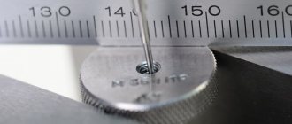
Inspection of conical surfaces
The taper of the outer surfaces is measured with a template or a universal inclinometer. For more accurate measurements, bushing gauges are used (Fig. 4.38), with which they check not only the angle of the cone, but also its diameters. Two or three marks are applied to the treated surface of the cone with a pencil, then a sleeve gauge is put on the cone being measured, lightly pressing on it and turning it along the axis. With a correctly executed cone, all marks are erased, and the end of the conical part is located between marks A and B.
When measuring conical holes, a plug gauge is used. The correct machining of a conical hole is determined (as when measuring external cones) by the mutual fit of the surfaces of the part and the plug gauge. If a thin layer of paint applied to a plug gauge is erased at a small diameter, then the cone angle in the part is large, and if at a large diameter, the angle is small.