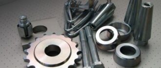
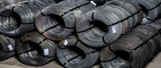
There are a whole lot of metal parts, they differ in their shape, weight, quality, therefore the types of metal cutting will also differ from each other. To manufacture any part, you will need metal material, it can be: welded blanks, plastics, stampings, castings, rolled sections, forgings. Such names can be combined into one group called “blanks”.
In order for the part to meet all specified parameters, the turner or miller must remove all excess metal from the workpiece. Until the desired shape is obtained, the master will process the part using a metal cutting machine or hand-held metalworking equipment. That unnecessary layer of metal removed is called “machining allowance.” This is the whole essence of metal cutting.
Metal processing
How the process works
The essence of the operation is to remove the top layer from the workpiece using a cutting tool. The depth of the cut is determined by the target. The main task is to give the steel the desired shape.
There is no universal device that can handle any product, since each has different lines and sizes. Along with a variety of parts, a large number of machines are also produced.
There are also many technologies that process materials by cutting, these include:
- turning - for cylindrical steel elements;
- drilling - for the formation of through and blind holes;
- milling - for working with flat and shaped surfaces;
- planing - to remove the top layer;
- chiselling - to form grooves and grooves, teeth;
- grinding - to achieve the desired degree of roughness.
This is an incomplete list, but the most popular settings. It should be noted that the equipment has varying degrees of versatility and automation.
content .. 41 42Chapter 12 MECHANICAL AND ELECTRICAL PROCESSING OF MATERIALS
12.1. Cutting materials
Cutting is the process of removing excess material (allowance) from a workpiece with a cutting tool to obtain a part with specified dimensions and roughness (surface quality). Waste during cutting is chips, which can be different (chipped, broken, drained, etc.) depending on the properties of the material, cutting speed, cross-section of the layer being removed and the condition of the tool: cutting angle, sharpening, cutting edge material, etc. When cutting the workpiece and the cutting tool experience large deformations and loads, which turn into heat, which is distributed between the chips (up to 80%), the workpiece and the cutting tool. The temperature of the tool cutting edge is always higher than the chip temperature. Depending on the cutting mode, the heating temperature is redistributed. Thus, with increasing cutting speed, the amount of heat transferred to the workpiece decreases, and to the tool and chips it increases.
During the cutting process, the tool is subjected to elastic deformation, and the material being processed—the metal layer being cut, the cutting surface and the surface layer (I...2 mm) behind the cut line—is subject to plastic deformation. The processed material, when deformed, is strengthened (hardened), as a result of which its hardness increases, and this, in turn, reduces the wear of rubbing parts in various devices and increases fatigue strength. The hardening of soft and ductile metals is much stronger than that of hard ones. The hardness of the cold-worked steel layer, depending on the cutting mode, increases by 2–4 times compared to the hardness before processing.
Cutting is carried out with a special tool. The cutting tool is a wedge that is inserted into the material with a force P (Fig. I2.I) to perform the cutting work. This is possible if the hardness of the wedge material significantly exceeds the hardness of the material being processed. At the stage of introducing the wedge into the material, a wedging force is created, which acts in opposite directions and can be five or more times greater than the applied force. Moreover, the sharper the wedge, the greater the wedging force at the same force P. But the wedge angle can only be reduced to a certain amount.
since in this case its strength can be significantly reduced. At the beginning of cutting, the cut layer of material experiences compression until the compression force is greater than the adhesion forces of microparticles of the material. At this moment, individual pieces a-e from the material being processed (workpiece 3) begin to chip (cut off), from which chips 1 are collected. The angle of the cleavage plane for steel can be 145... 155°.
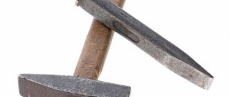
As noted earlier, cutting is the most common processing method. One of the main tools in this case is a cutter, which is an improved wedge. All cutting tools are a type of chisel. There are a lot of cutter designs; they are divided according to material, purpose, machine equipment, left and right, as well as other characteristics. The main types of cutters are passing, boring, scoring, cutting, threading, etc. Since the cutters are designed approximately the same, it is sufficient to consider in detail any of them, for example, a cutting cutter (Fig. 12.2).
Cutting cutters are used to separate material on lathes, planers, turrets and automatic lathes. The cutting part of the cutters is usually made of high-speed steel or carbide. On automatic lathes, in addition to the usual ones, round cutters are used. If lathes have two supports, then you can perform counter cutting with two cutters simultaneously. To obtain high productivity and long-term durability of the cutting tool in relation to the properties of the materials being cut, the cutters must have optimal dimensions of the cutting part, determined by the main rake and rear angles. For example, for steel the main rake angle is 25°, and the main back angle is 8°, and for brittle and hard bronzes it is 0...5° and 6...8°, respectively. In addition, the side surfaces of the cutting
cutters must have an undercut angle a = 1 ..2° and clearance angles
a, on the side surfaces of the cutter (a1| = 2…3°). To obtain a clean surface of the material being cut, it is recommended to make the cutting blade of the cutter inclined (cf, = 8... 15° for steel and 20...25° for soft materials). The width of the cut depends on the diameter of the workpiece. So, for a workpiece with a diameter of up to 25 mm, the width of the cutter is 3...4 mm, and for a workpiece with a diameter of 60...100 mm it is 5...6 mm. Angle p is called the sharpening angle or sharpening angle.
When separating metals with cutting cutters, it is necessary to cool the cut site (material and tool) generously, install the cutter strictly in the center of the material being cut (for carbide cutters it is recommended to install it 0.5 ... 1 mm below the center) and when cutting with a large cutting depth, the process is carried out with an inverted cutter and during reverse rotation of the processed material.
Possible types of mechanical processing of materials by cutting are turning, milling, drilling and planing.
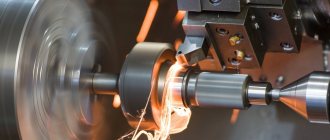
When turning (Fig. 12.3, a), the workpiece rotates onto a through cutter, which, with a given feed and depth of cut, moves to the left, removing chips. The cutter is usually installed in the center of the workpiece being processed.
Milling (Fig. 12.3, b) is performed with a cylindrical cutter, which rotates towards the fed workpiece.
Drilling (Fig. 12.3, b?) is carried out with a twist drill, which rotates and is simultaneously lowered into the workpiece. Assessing the nature of the emerging chips, we can conclude that the drill is properly sharpened and both of its cutting edges are working at the same time (for most metals, the chips are draining).
Planing (Fig. 12.3, d) is performed by a planing cutter, which makes a working stroke when moving forward, and an idle stroke when moving backward. At this moment, it leans back, and the workpiece moves to the right at a given feed.
Of the different types of metal cutting, we will get acquainted with only a few - cutting teeth, broaching, grinding, etc.
Gear and gear teeth are made in a variety of ways. For example, cutting the teeth of cylindrical wheels using the copying method is carried out using disk modular cutters (Fig. 12.4, a) on horizontal milling machines and finger modular cutters (Fig. 12.4, b) on vertical milling machines using dividing heads. With this cutting method, the tooth cavities correspond to the shape and dimensions (modulus) of the tool.
Rice. 12.3. Types of machining by cutting: a - turning; 6 — milling; c - drilling; g - planing; - - movement of the tool; - - «- - movement of the workpiece
Rice. 12.4. The main methods of cutting teeth: a, b - copying using modular disk and finger cutters; c — running in with a hob cutter; g - chiselling with a comb; —" » — tool movement; —->- — workpiece movement
More productive is the method of cutting teeth by rolling (Fig. 12.4, c), in which a worm cutter of a given module rolls a rotating workpiece, while the latter rises towards the tool until the teeth are completely cut. Cutting of teeth is carried out on horizontal milling machines or on special gear cutting machines. In addition to teeth, hobs are used to cut threads, splines, etc.
With a comb, gear teeth are made by the chiselling method (Fig. 12.4, d), in which the gear blank rotates slowly, and the comb moves down and up perpendicular to the plane of the workpiece, alternating working strokes with idle strokes.
Broaching is a method of processing materials by cutting and surface plastic deformation of the internal and external surfaces of workpieces on broaching machines. This processing method is widely used in large-scale and mass production due to its high productivity and high processing accuracy, several times superior to planing, chiselling or milling.
Using broaching, through holes of various configurations are processed (Fig. 12.5, a) with an internal size of up to 300 mm. Previously, holes are made in the workpieces intended for broaching using drills or cutters, the length of which usually does not exceed three times their diameter.
The tool for broaching is a broach (Fig. 12.5, b) - a multi-edged cutting tool designed for processing internal and external surfaces of different profiles. According to the shape of the processed surfaces, broaches are divided into flat, round and shaped. A broach is a rod with teeth, the sizes of which gradually increase, and the shape changes from the original to the specified one (for example, from round to hexagonal).
External broaching produces straight and spiral teeth on gears and sectors, straight and helical grooves, splines, etc. Broaching machines are vertical (mainly for external broaching) and horizontal (for internal broaching) with a hydraulic drive of the slider, ensuring smooth operation.
Rice. 12.5. Broaching: a - holes of different configurations obtained by broaching; b - broach
Reaming is a method of finishing cylindrical and conical holes with a diameter of up to 100 mm by cutting using a metal-cutting tool - a reamer, which provides a degree of processing accuracy of 7-9 grade and a roughness of Ra 0.100 microns. In this case, a slight removal (several tens of micrometers) of the processed material occurs and the thin surface layer is strengthened. Before reaming, the hole in the part is processed with a drill or countersink, leaving an appropriate allowance for final processing.
The reamer (see Fig. 7.1, g) is a multi-edged cutting tool made of tool materials designed for precise and finishing processing. The reamer usually has an even (6-12) number of teeth, which gives it high stability in the hole, increased rigidity compared to a drill, and the ability to produce holes with greater accuracy. It usually consists of a guide cone, cutting and calibrating parts that form the working part of the reamer, as well as a neck and a shank with a square. Reamers are divided: by method of application - into manual and machine ones, by the nature of fastening - into tail and attachment ones, by design - into solid, prefabricated, adjustable with insert knives, etc.
Hard and brittle materials (glass, ceramics, semiconductor materials) can be cut with diamond tools - diamond cutting discs (circles) and scribing. There are two types of diamond blades - with outer and inner cutting edges. Diamond blades with an outer cutting edge carved with diamond are used for cutting when the accuracy requirements are low and the cost of waste material is insignificant. Such discs, depending on the diameter, make it possible to cut workpieces with a thickness (diameter) of up to 30 mm with a thickness of the tool itself (metal base) of 0.5...0.6 mm. A diamond disk is used to cut workpieces at a rotation speed of 2*000...3,000 min1 and abundant cooling with water or special coolants.
Discs 1 (Fig. 12.6) with an internal cutting edge 2, which is carved with diamond, are used in special machines on which hard brittle materials are cut, such as ingots of semiconductor materials, into wafers with a diameter of up to 150 mm. The thickness of the cut plates is 200...300 microns with approximately the same cutting width.
Scribing is a method of dividing thin and fragile wafers (for example, ceramics, glass-ceramics, semiconductors) into separate parts, consisting of two stages - making cuts (scores, scratches) on the plate with a depth of 10...15 microns with a diamond cutter (scriber) and subsequent breaking along it on a soft support when stretching or rolling the plate with a roller.
Grinding is, as a rule, a finishing operation in the manufacture of metalworking (cutting) products. Typically, parts that have undergone heat treatment are ground, obtaining the specified dimensions and roughness. Processing is carried out with grinding wheels, in which the cutters are grains of diamond, corundum, carborundum, secured with a bond. During operation, the wheels self-sharpen: worn-out cutting particles fall off, and new ones are exposed to replace them and begin to work.
Sanding is done in different ways. During external cylindrical grinding, the part / (Fig. 12.7, a), as a rule, rotates in the centers and moves longitudinally, and the abrasive grinding wheel 2 rotates towards the part and can be fed towards it, performing an initial plunge to a given depth.
In external flat grinding, the flat surfaces of the part / (Fig. 12.7. b) are processed with the peripheral part of the grinding wheel or its end - cup 3. The part to be ground is held by the magnet of the grinding machine table, and the rotating grinding wheel can be lowered and raised, the workpiece (part) is fed moving the machine table in two directions.
Through internal grinding, through, blind, stepped cylindrical and conical holes are processed. The part to be sanded 1 (Fig. 12.7, c) is fixed in the chuck 4, together with which it rotates in the direction of the arrow. The grinding wheel has its own drive, with the help of which it rotates around its own axis, moves back and forth and can move perpendicular to its axis of rotation to cut into the workpiece. Typically, an internal grinding tool consisting of an abrasive wheel and a mandrel is called a grinding head 5.
Rice. 12.6. Cutting material with a disk with an internal cutting edge: 1 - disk; 2 - internal cutting edge; 3 - hard brittle material; — — movement of the disk; —-► — movement of the material being cut
Centerless grinding is widely used in serial and mass production for processing cylindrical, predominantly smooth parts with longitudinal automatic feed. The advantage of centerless grinding is high productivity and high dimensional stability of the grinded parts. When grinding on a centerless grinding machine, part 1 (Fig. 12.7, d), passing between two abrasive wheels - grinding 2 and leading 7, rests on knife 6, and the center of the part to be ground is slightly higher than the centers of the circles. The driving wheel 7 rotates at a sliding speed over the machined surface of 10...50 m/min, and grinding is carried out by wheel 2, which rotates at a grinding speed of 30...35 m/s.
Rice. 12.7. Different grinding methods: a - external round; 6 — outer flat; c - internal; g - centerless; ] - detail; 2 - grinding wheel; 3 - cup; 4 - cartridge; 5 — grinding head; 6 - knife; 7 - leading circle; -"- - movement of the grinding wheel; - -►- - movement of the workpiece
In the grinding process with longitudinal feed, the drive wheel is installed so that its axis is inclined to the axis of the grinding wheel. Due to the rotation of the drive wheel, the grinded part, along with the circular one, also undergoes longitudinal movement. The greater the angle of inclination of the driving circle, the greater the magnitude of the longitudinal movement. When grinding short parts, this angle is 1...2.5°, and when grinding rods - 3...4.5°. Sanding can be done in several passes. When rough grinding, 0.05...0.03 mm is removed in one pass.
For all types of grinding, the workpieces and grinding wheels must be cooled with special liquids, which simultaneously remove cutting waste and abrasive dust.
Application of technology
Cutting of steel structures is carried out through metal cutting in large workshops, as well as at home. In production, such metalworking equipment is installed in virtually every plant where work with metal structures is carried out - from the creation of the largest multi-ton parts to microscopic electronic circuit boards. All areas of mechanical engineering (aircraft manufacturing, shipbuilding, automobile manufacturing, etc.), as well as the manufacture of consumer products (household appliances, furniture with metal elements) use cutting technology.
Theory and practice
Theoretical works on metalworking began to appear in the 19th century along with the first machines. The main task of science is to increase the processing speed while maintaining the staticity and durability of the cutter, as well as:
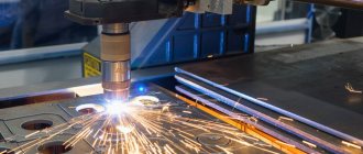
- search and development of alternative methods (plasma, gas, laser cutting);
- minimizing the generation of heat during friction;
- methods of cooling the structure.
Scientific developments are closely related to the results of research in materials science, since the main direction of this science is the study of the physical and chemical characteristics of the alloy - their strength, hardness, plasticity temperature, etc.
Features of the use of machines
Despite the same essence of the process - mechanical removal of the top layer, the procedure itself can be performed in different ways. The main difference lies in two parameters:
- how the feeding occurs - does the workpiece move or not, for example, in a lathe it rotates;
- how the instrument moves and its features.
The basis for the remaining cutting edges is the cutter. It is the most versatile and can perform many operations; the rest of the products are its modifications.
The workpiece is installed in special clamps on the machine and secured in spindles. Then a tool is clamped in the support - a milling cutter, drill, cutter, grinding disc, etc. All tools are selected depending on the hardness of the metal and its qualities.
Basic concepts and definitions of the cutting process;
General provisions
for MATERIALS AND CUTTING TOOLS
The cutting process is the sequential cutting of the workpiece metal with a cutting tool, removing it in the form of chips in order to obtain a part of a certain shape and size specified by the drawing, and to ensure a surface quality determined by the technology.
On the workpiece being processed, the following are distinguished: the machined surface, the machined surface and the cutting surface.
The machined surface is the surface that is completely or partially removed during cutting. The machined surface is the surface formed after chips are removed. The cutting surface is the surface that is formed by the cutting blade of the tool and is transitional between the processed and machined surfaces.
In Fig. 1. shows the main surfaces of the workpiece and the main movements necessary to carry out the cutting process during turning.
To carry out the cutting process, at least the following conditions are required [3]:
a) the tool must have the appropriate shape and
rational sharpening geometry;
b) the hardness of the cutting part of the tool should be significant
significantly higher than the hardness of the material being processed;
c) the tool and the workpiece during the cutting process must move relative to each other strictly along specified trajectories;
d) all mutual movements must occur at certain speeds of the main movement and feed movement, depending on various technological factors and processing conditions.
To carry out the cutting process, it is necessary to have at least two movements, namely: the main cutting movement and the feed movement. Main cutting movement
(
) is a rectilinear translational or rotational movement of a workpiece or cutting tool, occurring at the highest speed. Feed movement
is a linear translational or rotational movement of a cutting tool or workpiece, the speed of which is less than the speed of the main cutting movement and which is intended to spread the separation of a layer of material over the entire processed surface.
When processing on lathes, the main cutting movement (rotation) is performed by the workpiece, and the tool produces the feed movement (see Fig. 1). In the case of work on boring, drilling and milling machines, on the contrary, the main movement is performed by the tools, and the feed movement can be carried out by both the workpiece and the tool.
The speed of the main cutting movement during turning is set in (m/min), which is calculated by the formula
, where is the diameter of the workpiece being processed, mm; — workpiece rotation speed, rpm.
Feed speed
or simply the feed can be specified in (mm/min) or (mm/rev). When turning, there are two types of feeds: - minute feed (mm/min), which shows how far the tool will move in 1 minute; — feed per one revolution of the workpiece (mm/rev), which shows how far the tool will move in 1 complete one.
When turning, set
, which are called cutting mode elements. Depth of cut (mm) is the distance from the machined surface of the workpiece to the machined one, measured along the normal.
Cutting feature
Regardless of the main method used for processing metals by cutting, a pattern emerges - about 20% of the material becomes surplus, chips. In fact, all classical procedures meet this requirement, except, perhaps, grinding. But grinding is often a finishing metalworking process that also involves turning or milling. This is not economically viable, but nothing can be done. However, modern machines operating on the principle of laser or plasma cutting produce such precise cuts, as well as thin sawing, that the amount of waste becomes minimal.
This is a general remark, now let's move on to specifics.
Existing methods of cutting metal
Let's take a detailed look at the main methods of metal cutting, what they are, how they are performed, etc.
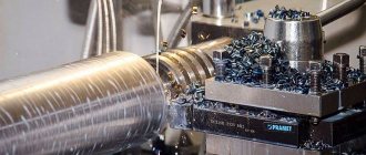
1. Turning (turning). Performed when the workpiece is not too different in size from the desired part. This process can be performed on the following equipment (machines): turning, milling, drilling, grinding, slotting, planing, etc. For this cutting, a lathe cutter is used. The process occurs at a high speed of rotation of the part, which is provided by the cutter. This movement is called the “main”. And the cutter moves slowly and progressively, along or across. This type of movement is called “feed movement”. The cutting speed is determined by the main movement.
2. Drilling. These are methods of processing metals by cutting, where the name speaks for itself. Happens on any machine where there is a drill. The workpiece is clamped firmly in a vice, and the drill rotates with slow translational movements in one straight line. As a result, a hole appears in the part with a diameter equal to the size of the drill.
3. Milling. Such methods of processing metals by cutting can only be performed on special tables-machines - horizontal milling machines. The main tool of the machine operator performing metal milling, which makes the main movement, is the milling cutter. The feed movement is carried out in the longitudinal direction of the workpiece; it occurs at right angles to the movement of the machine. The future part is firmly clamped on the table, and it remains motionless all the time.
4. Planing. Occurs on transverse planing equipment and machines. The workpiece is processed with a cutter that performs slow movements in a given direction and back. The main movement belongs to the tool - a slightly curved cutter. The feed movement is performed by the workpiece, and it is not continuous, but intermittent. The direction of the last movement is directly perpendicular to the main one. In this type of machine, the cutting movement is calculated by adding the working and idle strokes.
5. Sanding. The activity is carried out using a grinding wheel on cylindrical grinding machines. The cutting wheel makes rotational movements, and the workpiece receives a linear and circular feed, but if a cylindrical part is turned. When the workpiece is a flat surface, the workpiece receives feed only in the forward direction.
The exhibition held in Moscow “Metalworking 2013” amazes with the presence of modern equipment. Photos of the equipment with which are presented in the following story:
The use of a lathe is the main type of metal cutting
The equipment is designed like this. There is a bed - this is a strong base that is mounted on the foundation to support the weight of the installation itself along with the material being processed. On the sides are the front and rear headstock. One simply plays the role of a holder, and the second contains a motor inside itself and transmits rotational motion through the spindles to the workpiece. It, in turn, rotates at the speed selected by the operator. Installation can be horizontal (usually) or vertical.
The second feed goes to the support in which the cutter is clamped. Using the handle and control wheel, the cutter moves the tool for cutting.
There are CNC machines. They have a high degree of automation - right down to installing the workpiece and removing the part, as well as performing additional functions - chip removal and supply of cutting fluid.
You can work with cylinders and cones - hollow and solid.
Increasing the durability of the lathe
When one metal comes into contact with another, a rapid grinding of the tool naturally occurs, and the main condition for the work is maintaining a high degree of sharpening of the cutting edge.
In solving this problem, engineers considered which material would perform better and last longer during turning. Initially, classic tool steel with a high amount of carbon was used. It is very durable, but still did not meet the high needs of developers.
Then the chemical composition of the alloy was changed. adding tungsten. The element led to increased hardness, and at the same time it became possible to carry out the metalworking procedure faster, which is why such equipment was called high-speed equipment. But this speed did not satisfy the engineers.
Now they use perfect alloys with maximum resistance to elevated temperatures. They can withstand temperatures up to 100 degrees, so they do not deform during operation. As we know, the higher the speed. the stronger the heating, so these materials helped solve the issue of speed limits.
Milling as a metal cutting technology
A milling cutter is a more versatile version of a cutter. This tool is also replacing planing; factories no longer install planing machines, since milling machines allow many operations to be performed. The workpiece is positioned vertically or horizontally, depending on the design features of the equipment. Then the part begins to move, the feed is longitudinal, the cutter begins to rotate. The interaction of two simultaneous feeds and the ability to work in several planes and coordinate systems makes it possible to achieve a variety of shapes and work with steel even in hard-to-reach places.
Gas method
Let's consider a fairly common method of influencing metal, which has been actively used for many years. This is gas cutting. It is quite popular and cost-effective. In another way, it is also called oxygen, since in this case the process of action on the metal is thermal in nature. There is a stream of oxygen after the work is completed and removes the remaining liquid oxide. To begin with, the upper edge of the part is heated. Depending on the chemical composition of the material (for example steel), its ignition temperature can range from 1000 to 1200 degrees.
Gas cutting can be used to process medium alloy, low alloy or carbon steel. The thickness of the metal sheet or other product must be a maximum of 300 millimeters. The gas-oxygen method of metal processing has its advantages:
- Low processing costs.
- There is no need to work with the edge after the procedure is completed.
- Availability of straight and diagonal cutting of products at different angles.
- You can use thick metal sheets.
Grinding Features
The task of grinding equipment is to remove a thin top layer in order to eliminate visible defects, level the surface and cut-in, and achieve the required degree of roughness.
The machine is equipped with an abrasive disc. This is the main sanding tool. The surface and end part are coated with a special compound that retains small abrasive particles. The grains can be of different fractions, they are located symmetrically and turned at different angles by the cutting edges in order to partially remove chips.
Metal cutting using plasma cutting technology - what is it?
During the process, an electric arc, like welding, occurs between the electrode (or metal surface) and the nozzle. A jet of compressed air under high pressure enters the plasmatron. Here instant heating occurs from 8,000 degrees or more, up to 30 thousand. Oxygen is ionized as it passes through the electric arc. It turns out that plasma is formed, that is, a hot stream of air under high pressure, which has a charge.
Passing through the nozzle, the flow develops an incredible speed - about 3 meters per second. Under the influence of a plasma cutter, the metal simply begins to melt, and oxygen blows out the molten drops.
Key Benefits
The advantages include:
- high machinability of metals by cutting - you can use any, even refractory and durable materials;
- high speed;
- any direction of the nozzle, the possibility of artistic cutting;
- maximum steel thickness;
- good edge quality;
- environmentally friendly, low emissions of substances into the atmosphere;
- safety because there are no explosive cylinders.
Saving time and money
Since the cut is clean and the amount of waste is minimal, you can save money because finishing is not required. An additional advantage is the short duration of the operation and the possibility of installing CNC. This allows you to reduce operator work time.
Features of the laser method
Another innovative method that has become widespread. One of the advantages is the ability to work not only with metals, but also with wood and plastic.
Description
Laser radiation heats the steel at a point, it begins to melt and then evaporate. A gas (most often oxygen) is supplied to the work area, which helps get rid of residues and also cools the area.
Due to high energy costs, the method is used only with thin-sheet products.
Advantages of the method
The advantages include:
- There is no mechanical contact, so the risk of deformation of even the most fragile parts is minimized.
- The thickness of the processed sheet is from 0.2 to 300 mm, depending on the material.
- High speed.
- Small amount of waste.
- Clean cut.
- Maximum accuracy.
Cutting materials
Home » Articles » Professionally about metalworking » Metal cuttingWe recommend purchasing:
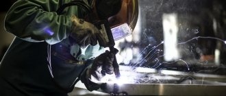
Installations for automatic welding of longitudinal seams of shells - in stock!
High performance, convenience, ease of operation and reliability in operation.
Welding screens and protective curtains are in stock!
Radiation protection when welding and cutting. Big choice. Delivery throughout Russia!
Materials used in mechanical engineering for the manufacture of machine parts and mechanisms, devices, and devices that can withstand force loads are called structural materials. They are divided into three classes:
- metals (alloys based on iron, nickel, copper, aluminum, magnesium, titanium and other metals);
- non-metals (plastics, ceramics, glass, rubber, etc.);
- composite materials.
In mechanical engineering, the most common and traditionally processed by cutting are metal structural materials, so the book will consider only the processes of processing metals by cutting on metal-cutting machines. The following metals are subjected to cutting processing: cast iron, steel, non-ferrous metals and their alloys.
Cast iron is an alloy of iron with carbon, silicon, manganese and other elements, and the carbon content is 2.14...4.5%. Gray, high-strength and malleable cast irons are most often processed by cutting.
Grades of gray cast iron are designated by the letters SCh (S - gray, Ch - cast iron) and two numbers indicating tensile strength. For example, SCh 18 is gray cast iron, tensile strength 180 MPa.
Depending on the mechanical properties, there are gray cast irons of low (SCh 10...SCh 18) and high (SCh 20...SCh 35) strength. For the manufacture of machine parts, cast iron grade SCH 15 is most often used; SC 20; SCh 30 and less commonly - cast iron grade SCh 35. The hardness of gray cast iron is HB 163...269. High-strength cast iron is produced by introducing magnesium (0.3...1%) or its alloy with nickel, copper, aluminum or silicon into liquid gray cast iron. The grades of this cast iron are designated by the letters HF (V - high-strength, Ch - cast iron) and two groups of numbers: the first means tensile strength, and the second - relative elongation. For example, VCh 45-5 is high-strength cast iron, tensile strength σв = 450 MPa, relative elongation δ = 5%. The hardness of high-strength cast iron is HB 156…269.
Malleable cast iron has high viscosity. The grades of this cast iron are designated by the letters KCh (K - malleable, Ch - cast iron) and two groups of numbers, the first means tensile strength, and the second - relative elongation. For example, KCh 50-4 is malleable cast iron, tensile strength σв = 500 MPa, relative elongation δ = 4%.
The machinability of cast gray cast iron workpieces by cutting is significantly influenced by the surface layer of the metal - the casting crust, the thickness of which is 0.15...0.5 mm, and the hardness HB is 285...321. As you move away from the surface, the hardness of cast iron decreases (НВ 187...229).
The cutting speed in the casting skin zone is 20...30% less than the cutting speed of the internal layers of metal. High-temperature annealing of cast iron castings allows you to increase the cutting speed by 1.5 ... 2 times.
Steel
called an alloy of iron with carbon (up to 2%) and other elements. The machinability of steel is greatly influenced by its chemical composition. With increasing carbon content, the mechanical strength of steel increases and, as a result, its cutting resistance increases, but the surface roughness increases. When processing steel with a low carbon content (0.1 ... 0.25%), better surface roughness is achieved. Based on their chemical composition, steels are divided into carbon and alloy.
Grades of carbon steel of ordinary quality are designated by the letters St and numbers from 0 to 6 (for example, StZ). The higher the number in the designation of the steel grade, the higher the carbon content. Grades of high-quality carbon structural steels are designated by numbers (08; 10; 15; 20; 25, etc.), which indicate the average carbon content in steel (in hundredths of a percent). For example, the carbon content in steel 15 is about 0.15%. Ultimate tensile strength (temporary tensile strength) for carbon steels σв = 300...700 MPa, it increases with increasing carbon content; hardness HB ≤ 230.
Grades of structural steel with increased and high machinability by cutting - automatic - are designated by the letter A (automatic steel) and numbers (carbon content in hundredths of a percent), for example A12; A20; AZO and A35. The tensile strength of these steels is σв = 600...800 MPa (for cold-drawn steel) and σв = 400... 700 MPa (for hot-rolled steel); hardness HB 160... 207. The increased sulfur content in free-cut steels ensures the necessary chip formation when working on machine tools, i.e. they are better processed than carbon steels of both ordinary quality and high quality.
Alloy steel grades are designated by numbers and letters (for example, 15Х; 40ХН; ЗОХГС; 20ХНЗАit.d.). The numbers show the average carbon content in the steel in hundredths of a percent, the letters behind the numbers indicate the presence of an alloying element (for example, P - boron; Yu - aluminum; C - silicon; T - titanium; F - vanadium; X - chromium; G - manganese; N - nickel; M - molybdenum; B - tungsten), the numbers after the letters are the content of the alloying element in percent (whole units), the letter A at the end of the grade means that the steel is high-quality. Tensile strength of alloy steels σв = 700... 1300 MPa (depending on the grade). An increase in the content of certain alloying elements (such as chromium, molybdenum, vanadium, tungsten, nickel) increases the strength and reduces the thermal conductivity of steels, which leads to a deterioration in their machinability. The presence of silicon impairs the machinability of steel due to the formation of silicate abrasive inclusions. Steels with a coarse-grained structure are processed better by cutting tools than steels with a fine-grained structure.
In some cases, to improve machinability, steel blanks are subjected to preliminary heat treatment. Hardness after annealing HB 180...270, and after heat treatment HRC 42...55.
Most often, workpieces made of the following non-ferrous metals are processed on metal-cutting machines: bronze, brass and duralumin.
Bronze
is an alloy of copper with tin, aluminum, manganese, silicon and other elements.
Bronze grades are designated by the letters Br, then by the initial letters of the main elements included in the alloy, and by numbers that show the average percentage of these elements. For example, bronze BrOTsSZ-12-5 contains on average 3% tin, 12% zinc, 5% lead and 80% copper. To improve workability and anti-friction properties, lead is introduced into the composition of bronzes.
Brass
is an alloy of copper and zinc. Brass grades are designated by the letter JI and numbers that show the average copper content (in percent). For example, JI62 brass contains 62% copper and 38% zinc. For better machinability, 1...2% lead is added to brass (automatic brass), and aluminum, nickel and other elements are added to increase strength. For example, brass LZhMts59-1-1 contains 59% copper, 1% iron, 1% manganese and 39% zinc.
Duralumin
is a deformable alloy of aluminum with copper (4...5%), magnesium (0.5%), manganese, silicon and iron. The designation of duralumin grades (D1; D6; D16, etc.) is not related to its chemical composition.
Conclusion
In the article we talked about the basics of metal cutting. There are many ways, but the technology remains the same and is used everywhere.
Contact Rosta LLC if you decide to buy devices for industrial use. We have manual and semi-automatic band saws in stock and on order, as well as pendulum, vertical and two-post units. The price of goods has been reduced by 1.5 - 2 times compared to foreign analogues.
To clarify the information you are interested in, contact our managers by phone 8; (473) 239−65−79;. They will answer all your questions.
Basic terminology when cutting metals
The depth of cut is the thickness of the metal, expressed in millimeters, which is removed with one movement of the machine. Feed is usually called the distance in millimeters made in one movement of the cutting object or by which it moves in one revolution. Cutting speed is the length, described in meters, that will be needed to operate the machine in a specific period of time. This unit of measurement is usually taken as a minute.
For those who want to personally understand the details, just type in a search engine - metal cutting technology directory.
For any type of cutting, effort must be made to help the tool separate the layer of metal. Such forces are called “cutting forces”; it is this concept that helps to find cutting resistance. The force with which the material resists the tool is called the “cutting coefficient,” and it is different for each metal. The size of this value is taken with a cross section of 1 mm².
We have already described above what types of machines there are according to their purpose, but according to the level of automation they are: hydraulic, equipped with program control, automatic and semi-automatic.
There are different methods in metal forming that are used in a wide variety of industries. Do you want to make a metal sauna stove yourself? How to build it with your own hands, read this article.
The final stage of working with metal is its hardening. How to produce it correctly, read the article at https://elsvarkin.ru/texnologiya/texnologiya-zakalki-i-otpuska-stali/ link.