Wave method
In the process of mass production of electronic devices, components are mounted on printed circuit boards on factory conveyor lines.
In this case, wave soldering is used. The essence of this technology, which appeared in the 50s of the last century, is as follows.
Printed circuit boards with electronic components installed on them move along a special conveyor. During the movement, the soldering areas are covered with flux, the board is preheated, and then passes over a bath of molten solder.
The bath is equipped with special nozzles that create a wave rising above the surface of the solder in the bath.
The board is positioned in such a way that the soldering points are in contact with the surface of the wave as the board moves along the bath. At this moment, the contact pads on the board and the leads of the soldered parts are wetted with solder.
The surface tension of liquid solder prevents it from completely draining from the surface of the board, which ensures soldering of parts to contact pads.
How I soldered my first electronic circuit
In the last post, I shared my modest successes in electronics, which at that moment were limited to assembling electronic circuits on a breadboard without any soldering.
Now I will brag about how I mastered doing something with a soldering iron. As, perhaps, in any business, if you have the right training manual, which, let me remind you, in my case is Charles Platt’s book “Electronics for Beginners,” this turned out to be not so difficult. I will list the tools that I used. Since they were not included in the starter for the book, they had to be additionally ordered:
- Soldering station ZD-99. The temperature can be adjusted from 150 to 450 degrees. The set includes a soldering iron holder and a sponge for cleaning the tip. Moisten the sponge with water, wring it out well, place it in a specially designated tray, and directly wipe the hot soldering iron during the soldering process.
- PCB holder with magnifying glass (aka third hand). It’s just a must-have so that nothing slips during soldering. The benefit of a magnifying glass is still questionable.
- Side cutters. Without them, you will not bite off the legs of the soldered elements of the circuit. In addition, I am quite good at removing insulation from wires with them.
- Tweezers. The need for it arises very quickly. You can't do without tweezers if you want to place elements on the board tightly enough.
Addition: The cheap ZD-99 soldering station broke down after a couple of months of use. I replaced it with an ELEMENT 878D soldering station with a hair dryer. As a more budget option without a hair dryer, I can also recommend the Simple Solder MK936 from CustomElectronics. To ensure high-quality soldering, currently I always solder with LTI-120 flux (UPD: Kingbo RMA-218 flux can be recommended as a good alternative). To remove insulation from wires, instead of side cutters, you should use a special tool, a stripper. For our purposes, a stripper for a wire thickness of 20 to 30 AWG (0.25-0.80 mm) is ideal.
Plus, I bought POS 61 solder 0.8 mm thick with flux. Similar solder is included in the starter, but it seemed to me that there was too little of it. As will be shown later, you may also need metal scissors. I found them at home. To prevent solder from dripping onto the table, I placed my third hand on an ordinary notepad. It seems that this is all about tools.
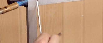
Platt teaches soldering as follows. Take two wires and solder them crosswise. If it works, solder the two wires in parallel. Use heat shrink tubing for insulation. To heat the heat shrink tubing, Platt advises purchasing an industrial hair dryer. However, I found that a regular hair dryer is fine. And if you don’t have a hairdryer, you can simply hold the pipe over a lighter. Once you've learned how to solder wires, solder the power supply wires to the jumper wires used on the breadboard. There is no longer any need to connect them with crocodile hooks. Comfortable.
Regarding the soldering itself. Simply connect the wires and the soldering iron tip at one point. Heat the wires for a few seconds (otherwise the solder will not stick to them). Then apply solder to the same point. That's all wisdom! Personally, I got it right the first time.
An important point about heat dissipation. To avoid overheating the elements during soldering, Platt advises using alligator clips on the legs. That is, the clamps can be used as a heat sink. For now I somehow manage without a heat sink, but it’s useful to know about this technique.
So, having learned how to work with a soldering iron, I wanted to solder something on the board so that everything would be just like with adults. Unfortunately, I was unable to make a blinking LED using a programmable unijunction transistor 2N6027, as described by Platt. The book gives three slightly different diagrams. I've tried them all. I tried changing the resistance of the resistors and the capacitance of the capacitors a little. Even changing the positions of the cathode and anode in case in my unijunction transistor they are positioned differently from Platt’s - nothing worked. I admit that I may have some burnt unijunction transistors.
As a result, I went to Google how flashing LEDs are made using ordinary bipolar NPN transistors. It turns out that the corresponding circuit is called a multivibrator and looks something like this:
The source of this circuit for gschem can be downloaded here. Unfortunately gschem can't draw criss-cross connections, so I just drew two straight lines in the middle of the diagram. In the picture, just in case, I emphasized that there is no connection diagram in the center. However, this should already be clear from the absence of a bold point.
The voltage of 5 volts was chosen because I wanted the circuit to be powered from USB, and the USB cable carries exactly 5 volts. You can read more about the USB cable and its wires here. Note that the red and black wire usually correspond to positive and negative respectively, but this is not generally guaranteed. You can use 12 volts, you won't burn anything. In general, the lower the voltage in the above circuit, the less often the LEDs blink. The capacitance of the capacitors can, in principle, be any. I tried using capacitors from 22 to 100 µF. The smaller the capacity, the more frequently the LEDs blink.
Setting process parameters
To obtain high-quality solder joints, it is necessary to adjust the technological parameters of the soldering line.
Firstly, the shape and orientation of the nozzle forms a wave crest with an optimal profile, and secondly, the board moving above the bath is located at a certain angle to the surface of the melt. Correctly selected process parameters make it possible to avoid defects in the form of jumpers between current-carrying tracks and sagging (icicles) on the terminals of parts.
Double wave soldering technology can be used for the same purpose. In this case, the first wave of solder is turbulent in nature, which allows better wetting of the soldered surface and penetration of solder into the mounting holes of the board.
The second wave, which has a smoother laminar flow, washes away flaws in the form of excess drops and sagging of solder, while forming the final geometry of the dumbbells.
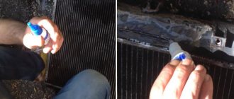
Wave soldering is not always automated. For example, on many assembly lines in China and other Asian countries, people install parts on the board, then apply flux and dip the board into a solder bath.
In this case, the board is taken by hand using a special grip and dipped into a bath of liquid solder.
Mounting SMD components
The wave soldering method is most often used for boards whose components are mounted on one side of the board, and pads and current-carrying tracks on the other.
The pin terminals of the elements are inserted into the through holes of the board and soldered on its reverse side. However, most modern electronic circuits are designed using so-called SMD components, secured by surface soldering. Such parts are soldered to the board on the same side on which they are installed.
The use of wave soldering technology for such elements has a number of features:
- when wave soldering SMD components, the board should be oriented downward with parts previously glued to it;
- a wave of molten solder washes over the body of the parts.
Thus, SMD components must be glued to the board with special glue before soldering.
At the same time, sometimes there are cases of parts peeling off during their contact with the melt wave, which leads to the appearance of defects. In addition, not all electronic components are able to withstand the temperature conditions that arise during the process of “bathing” in liquid solder. These circumstances limit the use of wave technology.
We should add one more negative feature inherent in this soldering technology. A large amount of molten solder in the bath, constantly in contact with open air, leads to the active formation of oxide.
What might you need for soldering?
Soldering requires a heat source. You can solder using an open flame, an electric spiral, or a laser beam. The latter allows you to solder even with pure metal. At home they mostly use an electric soldering iron. It is intended for:
- installation and repair of various electronic circuits;
- design and repair of electrical equipment;
- tinning a layer of solder on various metal products.
Soldering iron
Solder with a hand soldering iron, which is used for:
- warming up the connected components;
- heating the solder until it turns into a liquid state;
- applying liquid solder to the elements to be connected.
The soldering iron, which is shown in Figure 1, contains:
- a spiral heater made of nichrome wire insulated with mica film or fiberglass;
- copper tip, which is located inside the spiral;
- plastic or wooden handle;
- housing for placing a soldering iron tip and spiral.
Figure 1. 100-watt soldering iron with plastic handle and three-pole plug
Solder Paste Application
To attach SMD components to the board, other soldering technologies are usually used. As a rule, they are all based on the use of solder paste. This composition includes powdered solder, flux and filler.
Solder paste is applied to the contact pads of the board and the leads of the parts installed on them.
After this, the board is sent to a special oven, where the connections are heated in one of the following ways:
- steam-gas mixture;
- sources of infrared radiation;
- by convection method.
During the heating process, the solder paste melts and the contacts are soldered.
Why do microcracks form in soldering?
Microcracks around contacts mounted in a hole most often appear at contacts of massive elements (transformers, capacitors, chokes) due to board vibrations, even with high-quality soldering. Cracks often appear around the contacts of power connectors when force is applied to them. For example, frequent malfunctions of flash drives are associated with mechanical stress on the USB connector - over time, the contacts of the connectors peel off or even come off.
Microcracks in the solder on the contacts of SMD components appear from the same vibrations and thermal stresses. Also common causes are defects in soldering - cavities in the thickness of the solder, impurities, cold soldering, sagging, overheating, rapid cooling.
Microcracks in BGA ball contacts appear due to soldering defects - cold soldering, poor wettability of contact surfaces, rapid cooling, displacement during cooling, thermal stress.
Look how boards are soldered in China:
Automated technologies
In situations where electronic components have pins with very fine pitches, when soldering connectors with a large number of pins, and in other cases that require the use of very fine technology, a soldering robot is usually used.
A robotic manipulator for soldering boards is a precision device containing a coordinate table on which a board with parts placed on it is installed and a soldering head moving along three coordinate axes.
The head is equipped with a solder supply mechanism and a device for vacuum suction of excess solder.
Robotic automatic soldering of circuit boards is significantly inferior to the wave method in terms of speed, so it is used only in cases where the latter cannot be used.
In addition to the actual soldering, robots are often used to install parts on the board immediately before soldering them. Individual elements, the installation of which due to their complex non-standard shape (transformers, chokes, some types of microcircuits) are difficult to automate, are installed manually.
Therefore, even on large assembly lines of well-known companies that produce electronic equipment, there are areas where assembly is carried out by people.
In addition, product quality control is also often performed by humans. Boards with defects that can be eliminated are sent for modification, which is done manually with a soldering iron.
Recovery procedure
Before soldering the cable to the display, for example, you should fix the area to be restored on the insulating plate. The easiest way to do this is to use double-sided adhesive tape.
The fastening ensures mechanical rigidity during soldering and will provide additional strength to the solder joint in the future.
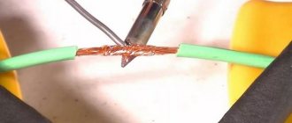
After this, you need to place the area with the broken cable under the screen with the microscope lens and, using a well-sharpened scalpel, clean the contact area from the insulation layer (approximately 1-1.5 mm from the break). Then, using a brush, apply a thin layer of the previously prepared rosin solution to the cleaned contact.
After thoroughly warming up the soldering iron, use its tip with a small amount of solder to touch the areas prepared for soldering. If there is excess solder, they are removed, since otherwise it will be possible to bridge adjacent tracks with them. Following this, a piece of conductor is taken with a conductor freed from varnish and well-tinned, which is then applied to one of the ends of the cable.
In conclusion, having measured the length of the core according to the size of the contact and biting off its remains with side cutters, it will be possible to solder the second end to the mating part of the restored section.