Engineers and other technical specialists know very well that each of the parts that make up machines and mechanisms must have strictly defined operational properties. The most important of them include durability, wear resistance, strength, as well as some other parameters. They depend not only on the material the part is made of, but also on many other factors. One of them is surface roughness.
In order to achieve the desired roughness state, the parts undergo finishing and finishing processing . It should be noted that as a result of this technological process, the surface layer, among other things, also acquires the required physical and mechanical properties.
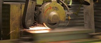
Grinding
In technology, grinding refers to a method of treating a metal surface that uses an abrasive material. Its cutting parts are abrasive grains.
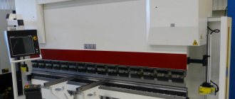
Finishing operations
Depending on the nature of the surfaces being processed, external, internal and flat grinding are distinguished.
From the point of view of the technological stages of processing the surfaces of parts, grinding is used for both finishing and finishing, as well as for roughing.
Lapping and finishing
In technology, these operations are finishing , and are used for mechanical processing of parts of various machines, mechanisms, and devices. Their use makes it possible to simultaneously achieve both high accuracy and the required surface roughness. The main tool for lapping and finishing is the so-called lapping. One of its main characteristics is that it is made from a much softer material than the one it is intended to process. It is most often used cast iron of such brands as SCh 20 and SCh 15, various grades of copper, other alloys, and even hard wood. To increase the efficiency of processing , special pastes or abrasive powder mixed with oil are applied to the surface of the parts before it.
The process itself, during which the surface of the lap is saturated with abrasive material, is called caricature. With the help of lapping, operations such as finishing of reamers, measuring tiles, smooth, round and threaded gauges are most often carried out.
Selection of surface treatment methods
Different surfaces can be processed in several ways, the choice of which depends on the requirements for these surfaces. Some methods are high-performance, but do not provide accuracy requirements, others provide accuracy requirements, but are low-performance.
A rational processing method in specific conditions is selected on the basis of the general principle of the greatest economy, which states: of all possible processing methods, the most economical one should be chosen
. If the most economical method cannot provide the necessary technical requirements, then the preliminary processing is carried out using the most economical method, and the final treatment is carried out in the method that provides the technical requirements.
Examples of choosing processing methods.
1. A highly productive way of processing cylindrical surfaces is to work with high feeds. If the surface roughness is high and it cannot be ensured when working with high feeds, then it is necessary to remove as much of the allowance as possible with high feeds, and finishing machining should be carried out with a low feed, which ensures the desired surface roughness.
2. Processing with a through cutter is more productive than with a scoring cutter, since the former has greater durability, therefore, when turning the outer cylindrical surfaces of smooth shafts and open ends, they tend to use through cutters. It is advantageous to process surfaces with a rectangular shoulder with a continuous thrust cutter, which is less resistant but ensures the formation of a rectangular shoulder.
3. The most productive way to process holes on a lathe in solid material is drilling. However, drilling does not provide high accuracy, roughness and precise centering of the hole axis, and is used when the technical requirements for the hole are not high. Large diameter holes (over 25 mm) can be machined by drilling and then reamed to the final size.
4. To obtain more accurate holes, in addition to drilling and reaming, processing with a cutter, countersink, and sometimes a reamer is used. The hole is countersinked to the final size after drilling, when it must be an exact size without special requirements for centering accuracy and surface roughness.
5. If, according to the technical conditions for the manufacture of a part, the hole must be strictly centered, then after drilling the hole is finally processed in a way that is less productive, but ensures strict centering of the hole. For example, you need to machine a hole with an accuracy of 0.05 mm, a roughness of Ra 1.6, and the axis of the hole must strictly coincide with the axis of the outer surface. To ensure precise centering of the hole (0.02 mm), after drilling it should be finished with a cutter, i.e. in a manner that ensures strict centering.
6. Cutting fastening threads with a triangular profile is more productively performed using dies and taps. If these threads are subject to high demands on accuracy in size and alignment in relation to other surfaces of the part, they have to be cut in a more accurate, but less productive way - with cutters.
Selecting installation bases
When developing technological processes for machining parts, it is important to correctly install and secure parts on machines. In most cases, the accuracy of the dimensions and relative position of the surfaces of the part depends on how the part is installed and secured on the machine. The surfaces of the part with which it is mounted for processing on the machine are called mounting bases.
The untreated surfaces of the workpiece are called rough bases, and the processed surfaces are called finishing ones. Rough bases are used for first installation only. The workpiece is usually not removed from the machine until the finishing base has been prepared for the next installation. Finishing bases distinguish between main and auxiliary.
The main base is the base that belongs to a given part and is used to determine its position in the product (the surface of the hole of a gear wheel, pulley, etc. If the hole of a gear wheel, pulley, etc. is used as a base for installing a workpiece when processing it on a lathe, then the accuracy of the location processed surfaces will be much more accurate).
Some surfaces of the workpiece often have to be specially machined just to install it on the machine (center holes, pre-machined surfaces of the part, the surface of test grooves, etc.). Such surfaces are called auxiliary bases.
Selecting a draft base
When choosing a rough base, you should be guided by the following considerations:
1. For parts for which not all surfaces are processed, it is necessary to take surfaces that are not subject to processing as a rough base, so that the machined surfaces are positioned correctly relative to the unprocessed ones. For example, in cast gears, pulleys, brake discs, etc. The inner surfaces of the rim and the end surfaces are taken as the rough base.
2. If all surfaces of the part are processed, then the surface with the smallest processing allowance should be taken as the rough base. Then this allowance will be located symmetrically or parallel to the processed surfaces, which will eliminate the possibility of blackness appearing when processing the surface with the smallest allowance.
After completing the first operation, the rough bases must be replaced with finishing – processed bases. Re-installation of the workpiece on roughing bases is, as a rule, unacceptable, since the same position of the workpiece relative to the cutting tool will not be ensured in both installations. Surfaces taken as rough bases should be as smooth and clean as possible.
Selecting a finishing base
When choosing a finishing base, it is recommended to consider the following:
1. Take as the finishing base such surfaces that can be used for as many operations as possible, since when changing the mounting bases, the accuracy of the part will decrease.
2. Select surfaces on which it would be more convenient to install and secure the workpiece, ensuring the least deformation from cutting and clamping forces.
When choosing installation bases, we proceed from the general principle of “unity of bases”. This principle is formulated as follows: the total number of install bases in the processing process should be as small as possible
. The fewer surfaces are used as installation bases throughout the technological process, the more accurate the relative position of the surfaces will be.
The rules for choosing mounting bases for manufacturing parts individually and in batches are different, although they are based on the general principle of “unity of bases.”
When producing parts individually, a surface is taken as a rough (primary) base, which can serve as a base for processing all surfaces located on one side.
When manufacturing parts individually, the finished (subsequent) base is taken to be the processed surface, which allows you to securely fasten the workpiece and process all surfaces located on the other side.
When manufacturing parts in batches, installation bases are also selected based on the general principle of “unity of bases,” but at the same time, the subsequent base is selected first, and then the primary one. The finishing (subsequent) installation base is taken to be a surface that can serve as a base for processing as many surfaces as possible, or a surface that allows you to prepare such a base.
A surface that can serve as a base for preparing a subsequent base is taken as a rough (primary) base.
Diamond smoothing
In technology, diamond burnishing is understood as a finishing method in which plastic deformation of the previously processed surface occurs, carried out using a special tool sliding over it.
This finishing treatment is used to either completely eliminate or significantly reduce the irregularities that appeared on them during the previous processing.
One of the main features of this processing method is that in its process the hardness of the surface layer of the part increases. In this case, the workpiece rotates, and after each revolution the tool moves at the feed in the axial direction by a certain amount. Due to the fact that the feed is less than the width of the groove formed by the tool, the marks that are formed from it overlap many times.
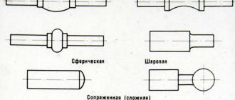
The tool smoothes the surface with its spherical working part. It itself is a metal mandrel in which a tip made of synthetic or natural diamond is fixed. The resistance of these crystals to mechanical stress is approximately the same.
What tools are used for this or that technology of machining parts?
There are various options for classifying CNC metal-cutting machines. Depending on what main types of processing they are intended for, CNC machines belong to one of the following technological groups - turning, milling, drilling, jig boring, drilling and milling (milling and boring), drilling and milling and boring, grinding, multi-purpose (multi-operational), machining centers intended for electrical processing, etc.
Depending on the principle of motion control determined by the CNC system, machine tools belong to one of three groups - the first is represented by equipment with CNC positional systems, the second - with contour CNC systems, and the third includes machines with combined CNC systems.
Depending on the number of tools used, machines can be single-tool or multi-tool. Multi-tooling equipment uses up to 12 machines. Those that are able to provide the highest concentration of operations have over 12 instruments. They are equipped with a special magazine to accommodate them. Such equipment is called multi-purpose.
Using multi-purpose CNC machines, a large number of operations are performed with one installation of a part on the machine, which becomes especially important with a significant number of transitions.
It is more expedient to use a console-less layout of medium-sized machines equipped with a cross table and a horizontal or vertical spindle (in the first case, a built-in rotary table is often used).
This arrangement is more rigid in comparison with the cantilever placement of the table, which increases the accuracy of processing, and due to the constant height of the table, the equipment is equipped with devices that allow you to automatically change workpieces. Using single- or double-column CNC machining centers with longitudinal table movement, you can process long parts. This arrangement of equipment is also more rigid in comparison with machines equipped with a cross table.
Machining technologies require that cutting tools experience significant stress, high temperatures, friction and wear, and therefore have special operating requirements. The working part of the tools must be made of materials of great hardness that can withstand increased stress in bending, tension, compression, and torsion.
Also, the materials from which the tools are made must remain hard under the influence of high heating temperatures (have high red resistance). A very important characteristic of a tool material is wear resistance. The higher it is, the slower the wear of the tool will occur and the higher its dimensional stability will be, i.e., the variation in the size of parts sequentially processed with the same tool should be minimal.
Successful technology for machining parts requires as little as possible content of scarce elements in the materials from which cutting tools are made.
- Carbon tool steels
contain 0.9–1.3% carbon. The tools are made from high-quality steels U10A, U11A, U12A. As a result of heat treatment of steel (HRC3 60-62), their red hardness is +200...+250 °C. At this temperature, the hardness of the steel decreases significantly and the tools become unsuitable for cutting. The use of such steels is limited, since the permissible cutting speed cannot be more than 15–18 m/min. They are used for the production of taps, dies, hacksaw blades, etc. - Alloyed tool steels.
They are based on carbon steels alloyed with chromium X, tungsten B, vanadium F, silicon C, etc. The red resistance of such steels (HRC3 62-64) after heat treatment is +250...+300 °C.Alloy steels differ from carbon steels in their increased toughness in the hardened state, higher hardenability, and less tendency to deformation and cracks during the hardening process. The permissible cutting speed varies from 15 to 25 m/min. Broaches, drills, taps, dies, and reamers are made from steels 9ХВГ, ХВГ, ХГ, 6ХС, 9ХС and others.
- High speed steels
containing 8.9–19% W, 3.8–4.4% Cz, 2–10% Co and V. Cutting tools are made from steels R9, R12, R18, R6MZ, R6M5, R9F5, R14F4, R18F2, R9K5 , R9K10, R10K5F2, R10K5F5. The red resistance of heat-treated high-speed steel tools (HRC3 62-65) is +600…+630 °C.The tool is characterized by increased wear resistance and the ability to work at speeds of up to 100 m/min. Tools of simple shapes (cutters, milling cutters, countersinks) are made from P9 steel. Shaped and complex tools (for cutting threads and teeth), which must be highly wear-resistant, are made of P18 steel.
- Cobalt high-speed steels
(R9K5, R18K5F2, R9K10) are suitable for the technology of machining parts in the manufacture of which difficult-to-process corrosion-resistant and heat-resistant steels and alloys were used - they are recommended for use when working in difficult conditions (with heavy intermittent cutting, vibration, poor cooling conditions). - Vanadium high-speed steels (R9F5, R14F4)
are used for the production of tools that are used to perform finishing (broaching, reaming, counterbore). They are suitable for working with parts made of difficult-to-cut materials when cutting chips with a small cross-section. - Tungsten-molybdenum steels (R9M4, R6MZ)
are recommended for the production of tools used for roughing; broaches, cutters and other tools are also made from them. Savings in high-speed steels are achieved through the production of prefabricated and welded tools. For the working part of the tool, high-speed steel is used, welded from carbon steel 45,50,40Х, etc. with a shank. Often, high-speed steel plates are used, welded to toolholders or tool bodies. - Metal-ceramic alloys
are a solid solution containing tungsten, titanium and tantalum carbide (WC, Ti C, Ta C) in metal cobalt (Co).Hard alloys are used in the form of plates produced by powder metallurgy, which have a specific shape and size. The plates are pressed and then sintered at temperatures from +1500 °C to +1900 °C. There is a division of hard alloys into several groups - tungsten is represented by alloys VK2, VKZ, VKZM, VK4, VK4V, VK6, VK6V, VK8, VK8V, VK10, VK15, VK20, VK25; titanium-tungsten includes alloys T30K4D15K6, T14K8, T5K10, T5K12V; titanium-tantalum tungsten - TT17K12, TT10K8B.
Carbide inserts (HRC3 86-92) are characterized by such qualities as high wear and red resistance (+800...+1000 °C), due to which the processing speed can be 800 m/min. The plates are soldered to holders or tool bodies using copper (brass) solders or attached mechanically.
- Mineral ceramics
is a synthetic material, the basis of which is alumina (A12 Oz) sintered at a temperature of +1720...+1750 °C. The red resistance of TsM-332 mineral ceramics (HRC 91-93) is +1200 °C. This material is highly wear-resistant and is used for the production of tools that require high dimensional stability. Due to its slight affinity with metals, the material does not stick to the workpieces.Tools using mineral ceramic inserts are suitable for semi-finishing of parts made of steel and non-ferrous metals under non-impact loading.
To increase the performance characteristics of such instruments, elements such as W, Mo, B, Ti, Ni are added to mineral ceramic plates. Such materials are called cermets. Cermets are of particular importance in the technology of machining parts made of difficult-to-machine steels and alloys.
- Diamonds
belong to a special group of materials. In industry, both natural (A) and synthetic diamonds of the ASO, ASR, ASB, ASC, ACC, ACM, ASN grades are used. This is the hardest material with increased red and wear resistance.Diamond cutters are widely used in such technologies of mechanical processing of parts as fine turning or boring of elements consisting of aluminum alloys, bronzes, brass and non-metallic materials.
Using diamond tools, they work with parts made of hard and semiconductor materials, germanium, silicon, ceramics, heat-resistant steels and alloys. When using such a tool, the quality of processed surfaces increases significantly. The processing speed is over 100 m/min. The surfaces of workpieces treated in this way are characterized by low roughness and high dimensional accuracy, since diamonds are characterized by significant dimensional stability.
Honing
In technology, honing is understood as such a procedure as the final finishing of a ground, bored or reamed hole using a hone - a special sliding head, which consists of several sliding abrasive bars.
The hone (honing head) is subject to two movements: reciprocating, along the axis, and rotational, around the axis of the hole being processed (it is relatively slow).
Honing is used to increase dimensional accuracy, reduce shape deviations, reduce surface roughness, and maintain the structure and microhardness of the surface layer of the material.
Super finishing
In technology, superfinishing is understood as a method of finishing surfaces in which their special purity is achieved. It is carried out using oscillating abrasive bars.
Superfinishing is used mainly to process the outer surfaces of various rotating bodies. The essence of this method is the principle of “non-repeating trace”. Its essence is that the same abrasive grain does not pass along the same path twice.
When superfinishing, the main working movement is the oscillation of the head, which, together with the bars, moves along the axis. The stroke of the bars ranges from 2 to 6 millimeters; per minute they make from 200 to 1000 double strokes. In this case, the workpiece is given a rotational movement.
Methods using surface treatment technologies
Technologies for surface treatment of materials currently represent one of the most developing areas of materials science. Methods associated with the creation of modified layers on the surface of materials have been sufficiently studied, tested and widely used in practice. Many of these methods or their improved variants can be considered as nanotechnology methods, since they allow the creation of nanosized and/or nanostructured layers on the surface of materials, composite materials with nanocomponents, and in some cases, nanomaterials in the form of nano- and micro-products. They are all united by a common scheme: gases, vapors or mixtures thereof are fed into the deposition chamber, where there is a substrate on which it is necessary to obtain a coating in the form of a film with the required properties. On the way to the substrate, gases are activated in various ways to produce active particles, molecules or radicals, from which the desired coating is formed. Activation can occur using electrical discharges of various types, catalytic action on gas molecules, and raising the temperature to the level necessary to initiate the required reaction in the gas phase or on the surface of the substrate.
Chemical vapor deposition.
One of the common methods for forming hard coatings on the surface of substrates or workpieces is chemical vapor deposition (CVD). The essence of this method is that the final product is formed on a substrate or any part as a result of the interaction of gaseous precursor substances or pyrolysis of vapor of a precursor substance. In this case, precursor substances under normal conditions can be not only gases, but also solids or liquids; in this case, they are sublimated or evaporated in a special zone of the reactor, and then transported to the target substrate using a carrier gas, which can be both inert and participate in synthesis. If the reaction produces gaseous by-products, they are removed from the reactor by flow of carrier gas or by vacuum pumping.
Carbonyls, halogens, and organometallic compounds are most often used as precursor substances. For example, metal halides are reduced by hydrogen to metal to form a halogen-hydrogen compound, and carbonyls are decomposed into metal and carbon monoxide by pyrolysis. Examples of reactions:
2MeG + H2 → 2Me + 2HG reduction reaction with hydrogen (G – halogen);
Mex(CO)y → xMe + yCO pyrolysis of carbonyls;
MeCl + CH4 → MeC + HCl interaction with intermediate components.
The most optimal course of chemical reactions occurs most often at temperatures from 500 to 1500 ºС. Therefore, the parts being processed are heated to these temperatures, which ensures the localization of the chemical reaction at the surface of the parts, as well as the optimal course of the process, obtaining coatings with specified properties and good adhesion. The formation of coatings occurs by successive layering of deposited material. The method ensures the production of coatings with a thickness of 1 - 20 microns at a speed of 0.01 - 0.1 microns/min.
CVD can be used to coat the internal surfaces of tubes and holes. It can be used to produce a wide variety of materials: silicon, carbon fiber, carbon nanotubes, silicon oxide, tungsten, silicon carbide, silicon nitride, titanium nitride, various dielectrics, as well as synthetic diamonds. The CVD process is often used in the semiconductor industry to create thin epitaxial layers.
The main disadvantage of the CVD method is the need to heat the parts to high temperatures. On the one hand, this has a negative effect on the mechanical properties and structure of the substrate, and on the other hand, it causes additional problems if it is necessary to obtain a nanostructured state of the coating itself.
The chemical vapor deposition process can be carried out using glow discharge plasma. There are two varieties of this method. In the first type - reactive sputtering - the target material in the form of ions interacts in the glow discharge plasma with ions of the active gaseous medium. A coating in the form of a compound is deposited on the surface of the workpieces. A typical example is the production of a titanium nitride coating when titanium and nitrogen ions interact in a glow discharge plasma. The second type is often called ion-activated chemical vapor deposition. In this case, chemical reactions similar to the CVD method are used, but due to their activation by the glow discharge plasma, the temperatures necessary for their occurrence are reduced to 200 - 300 ºС. However, in this case it is practically impossible to obtain coatings with a very high purity of the chemical composition, since due to insufficient desorption at a low temperature of the substrate, impurities of reaction gases can penetrate into the forming coating.
There is a wide variety of methods based on physical processes occurring on the surface of the substrate or workpiece. Among them, one can distinguish a group of physical vapor deposition methods: PVD (Physical Vapor Deposition). This group of methods is united by a common coating scheme and the use of vacuum. In them, the coating material is first transferred from the condensed state to the vapor state, then it is transported to the substrate or product to be coated. There, the coating material is deposited from the vapor phase and the coating is formed.
The classification of a method within a group is determined by the combination of evaporation, transport and deposition methods used. This group includes thermal vacuum evaporation, ion-plasma sputtering, ion implantation, and laser radiation treatment.
Thermal vacuum evaporation
carried out in vacuum at a pressure of the order of 10-3 – 10-5 Pa. At this pressure, the free path of atoms or molecules is on the order of several meters. The vapor phase of the sprayed substance obtained as a result of heating is freely deposited onto the substrate, which has a temperature much lower than the temperature of the vapor phase. Depending on the heating source, the following variants of the method have become widespread: electrothermal heating (directly passing an electric current through a sample in the form of a spiral or heating the substance in a crucible), heating using an RF inductor, evaporation due to an electric arc discharge, heating with an electron or laser beam. Most of these methods are designed for the evaporation of metallic materials. Heating in a crucible and the use of laser radiation make it possible to evaporate a wide range of materials. Crucible heating can be used to evaporate materials with a relatively low evaporation temperature. In this case, it is necessary to take into account the temperature and chemical resistance of the crucible material, which is used as graphite, aluminum oxide, boron nitride, molybdenum, etc. An important condition for choosing a material for the crucible is the absence of chemical interaction between it and the evaporated substance at high temperatures.
To create coatings from alloys and chemical compounds, it is necessary to evaporate each component from a separate source. This is due to the fact that when a complex substance evaporates, its components can have very different vapor pressure values. In this case, the composition of the vapor phase and, as a consequence, the composition of the coating will differ from the composition of the evaporated substance. In addition, the evaporation of compounds is often accompanied by processes of dissociation and/or association, which also interferes with obtaining the desired coating composition.
To provide better evaporation conditions and overcome a number of other disadvantages of evaporation from crucibles, electron beam evaporation is used. In this case, the electrically conductive evaporated material is placed in a water-cooled crucible and heated by an electron beam. The focusing spot of the electron beam on the surface of the evaporated material can reach 1 mm, so the melting zone will be significantly smaller than the entire volume of the material and, therefore, will not be in contact with the crucible. The disadvantage of electron beam evaporation, as well as evaporation from crucibles, is the difficulty of evaporating a material consisting of components with different vapor pressures at the same temperature, which complicates the production of coatings from metal alloys of a given composition. The use of laser light (pulsed or continuous wave) avoids most temperature and chemical limitations and eliminates the need for crucibles. Almost instantaneous evaporation of the substance makes it possible to maintain the ratio of chemical components in the deposited film the same as that of the evaporated material.
The advantages of the thermal vacuum evaporation method include the relative simplicity of equipment and process control, while the disadvantages are low adhesion of the coating due to the low energy of atoms or molecules deposited on the substrate and high sensitivity to the presence of foreign films and contaminants on the surface of the substrate. The impact of these shortcomings can be somewhat reduced through the use of special surface preparation methods (ultrasonic, chemical or electrochemical cleaning, ion etching).
Ion-plasma sputtering
based on the sputtering of targets from the desired substance by accelerated ions formed in a gas-discharge plasma. The simplest is cathode sputtering. In this case, the process is carried out in a special gas-discharge chamber at a working gas (argon) pressure of the order of 1 – 10 Pa. A constant voltage of the order of 1–5 kV is applied between the target cathode made of the sputtered material and the anode on which the substrate is fixed. This creates conditions for the occurrence of an independent gas discharge. The inert gas ions formed in this process bombard the cathode target and knock out atoms from its surface, which are deposited on a nearby substrate. The deposition rate with this method is relatively low - at the level of 0.1 µm/min.
The three-electrode sputtering scheme has wider capabilities. In it, the discharge current and voltage on the target are regulated independently of each other. Unlike the two-electron cathode sputtering scheme, in which electrons are emitted from the cathode through secondary electron emission, the three-electrode scheme uses thermionic emission. This makes it possible to significantly facilitate the formation of plasma and carry out the process at a higher vacuum (at the level of 0.1 Pa), which, in turn, ensures higher purity of the sprayed material. The deposition rate is about 1 µm/min. The disadvantage of this option is the noticeable heating of the substrate, reaching in some cases 300 – 500ºС.
Further development of three-electrode sputtering systems led to the creation of autonomous ion sources. The ion source is a gas-discharge chamber with a thermionic cathode into which working gas is supplied under pressure of ~0.5 Pa, which ensures a high concentration of ions. The gas-discharge chamber is separated from the deposition chamber by calibrated holes, which ensures a pressure difference, as a result of which the pressure in the deposition chamber, where the target and substrate are located, is on the order of 0.015 Pa. Some of the ions enter through the holes into the deposition chamber, accelerate and sputter the target. This design makes it possible to increase the target sputtering rate and improve the purity of films deposited on the substrate.
A type of cathode sputtering is high-frequency sputtering. The general circuit is generally similar to the two-electrode circuit, only instead of a constant voltage between the anode and the target cathode, a high-frequency voltage with an amplitude of 0.3 - 2 kV and a frequency of over 10 MHz is applied. This method makes it possible to sputter targets made of both electrically conductive and dielectric materials, and the sputtering efficiency is higher than that of a two-electrode circuit using a constant voltage.
In the magnetron sputtering method, mutually perpendicular electric and magnetic fields are used to form a gas-discharge plasma. This makes it possible to significantly reduce the working gas pressure in the chamber and localize the plasma near the target, as a result of which the target sputtering rate increases significantly. The method makes it possible to ensure a deposition rate of up to 1–2 μm/min and reduce substrate heating to 100–250 ºС.
Ion implantation
is the process of introduction (implantation) of high-energy ions into the surface layer of the target material. The process is carried out in a vacuum at a pressure of the order of 10-4 – 10-3 Pa using ion-beam accelerators (implanters). When ions fall on the modified material, they penetrate into it to a depth of 5–500 nm, depending on their energy. Conventionally, low-energy ion implantation with ion energy of 2–10 keV and high-energy implantation with ion energy of up to 400 keV are distinguished. Depending on the design of the implanter, the diameter of the ion beam spot on the surface of the material being processed can range from 10 to 200 mm, and the average current in the ion beam can range from 1 to 20 mA. The dose of ion irradiation is usually 1014 – 1018 cm-2.
During the interaction of ions bombarding a target with surface atoms of the modified material, a whole complex of complex processes occurs. In addition to the actual implantation of ions into the surface layer of the material, processes such as sputtering of the surface, the development of cascades of collisions with the formation of radiation defects, cascade (ballistic) mixing of material atoms in the surface layer, radiation-stimulated diffusion, the formation of metastable phases, radiation-stimulated segregation occur (redistribution of material atoms in the surface layer), etc. The relationship between these processes depends on the type of implanted ions, the modified material and the technological processing mode.
The main advantages of ion implantation as a method for creating modified surface nanolayers are: the ability to obtain almost any combination of materials in the surface nanolayer, independence from the solubility limits of components in the solid phase (i.e., it is possible to obtain alloys that are impossible under normal conditions due to thermodynamic limitations ), low temperatures of the modified material and the absence of noticeable changes in the dimensions, structure and properties of the base material, absence of adhesion problems, controllability of the processing depth, good reproducibility and stability of the process, high purity of the process in a vacuum, the ability to create complex surface nanostructures, the possibility of simultaneous or sequential implantation of ions of various materials.
The disadvantages of the method include: the shallow depth of penetration of ions into the material (especially at low energies), the occurrence of surface sputtering processes, the high cost and complexity of equipment, insufficient knowledge and the difficulty of controlling the entire complex of processes occurring during ion implantation.
Laser group of methods
based on surface treatment with laser radiation. With these methods, the nanostructural state is achieved in thin surface layers of metal materials or products obtained using traditional technologies by interacting the substance with high-density laser radiation. Pulsed laser radiation with an energy density of 103 – 1010 W/cm2 and a pulse time of 10-2 – 10-9 s is used. In a number of cases, continuous radiation from CO2 lasers with an energy density of 105 - 107 W/cm2 is used with beam scanning speeds that ensure the interaction time of the material with the radiation is 10-3 - 10-8 s. Under the influence of laser irradiation, a surface layer of material with a thickness of 0.1 - 100 microns melts very quickly and then solidifies with cooling rates of 104 - 108 K/s. In this case, the bulk of the metal material, due to the short duration of the thermal effect, does not heat up and provides high heat removal rates. High cooling rates make it possible to achieve a nanocrystalline or even amorphous structure. In this case, the nanocrystalline state is obtained by carrying out additional controlled crystallization during heat treatment.
Laser alloying or laser implantation is associated with the additional introduction of alloying substances into the melted surface layer. Such introduction can be carried out both by preliminary application of a thin film of the alloying substance on the surface of the material being processed, and by injection of powder particles (including nanoparticles) in a gas stream into the zone affected by laser radiation. In this case, alloying can pursue two main goals: firstly, the creation on the surface of a modified layer with a chemical composition and properties different from the base metal; secondly, facilitating the formation of a nanostructured or amorphous state during solidification of the molten surface layer.
Polishing
In technology, polishing refers to a finishing operation necessary to obtain a smooth and clean surface of a part. It is produced with special wheels on which a special abrasive powder mixed with lubricant is applied. Polishing is also carried out with soft wheels impregnated with graphite filler.
As a rule, before polishing, parts are sanded with elastic belts or wheels. This is necessary to ensure the required surface cleanliness.