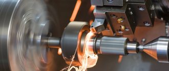
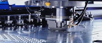
The most common methods for manufacturing parts with given geometric parameters include metal turning. The essence of this technique, which also makes it possible to obtain a surface with the required roughness, is that the excess layer of metal is removed from the workpiece.
Metal turning process
Equipment and tools
On lathes, workpieces are processed by rotating them around a horizontal and vertical axis.
The main tool used is cutters. All turning equipment is marked with the number “1” and is divided into 9 types, taking into account the features of the device. The tool rotates using a special device on the caliper. Grinding and milling work is performed on a lathe.
Types of lathes
There are main types of lathes used in production:
- screw-cutting lathe;
- turning-turret;
- rotary turning;
- turning and grinding;
- lobotocar.
Screw-cutting lathes are the most widely used. They process long parts such as shafts and short cylindrical ones.
Carousels are used for the manufacture of bushings, rings and other large parts whose diameter is greater than their height.
Classification of incisors
According to the location of the cutting edge and the direction of movement of the caliper, cutters are divided into two types:
- rights;
- left.
According to the shape of the working part:
- straight - the working part and the body have common lateral surfaces;
- bent - the cutting edge protrudes beyond the plane of the body and has a variable cross-section.
For external processing, types of cutters are used, named after the operations they perform:
- checkpoints;
- groove;
- shaped;
- threaded;
- boring
Lathe equipment is widely used for machining ends. At the same time, face and cutting cutters are installed on the caliper. In addition, the following are mounted on the tailstock:
- drill;
- countersink;
- taps;
- boring cutters.
There are certain geometric parameters of the cutter that are applied to the wedge. The cutting edge can be located at an angle to the direction of movement and perpendicular. For cutting tools - parallel to the axis of rotation.
Metal turning
Introduction of CNC
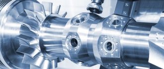
With the advent of CNC machines, the processing of parts with complex radial and involute surfaces has become much easier. Productivity has increased in the production of large batches.
Several operations are performed on one installation, including milling. The equipment may have 2 movable supports and several turrets.
What type of tools are needed for parts that are made on lathes?
All tools can be divided into cutting and auxiliary. The carver works with the following devices:
- Shaped cutter - the edge must coincide with the profile of the workpiece, represented by rolled rods.
- Centering drills - respectively, are necessary for drilling blind and through holes.
- Boring attachment – for boring cavities.
- Pass-through – suitable for roughing, semi-finishing and finishing of external and internal surfaces, for facing conical parts.
- Groove cutter.
- Cut-off.
- Carbide inserts are used in the manufacture of tool steel items.
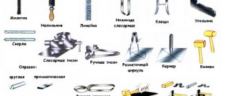
The image shows the approximate set of each turner:
If you were interested in what tools are used to process parts on lathes, pay attention to the photo. Equipment should always be kept clean and sharpened.
Evolution
Oddly enough, humanity has moved along the path of modernizing lathes very slowly. Only by the middle of the 16th century did machines for processing metal with a foot drive appear, and a little later - with a water drive. But the master’s rapidly weakening hand still held the cutter. The real problem was solving the following problems:
- production of metal parts of complex geometric shapes;
- applying threads, both external and especially internal;
- creation of gear wheels, so necessary in those days in a variety of industries.
The industrial and technological revolution that occurred in Europe (mainly in Great Britain) in the second half of the 18th century led to a real breakthrough in the evolution of metal turning. More and more metal parts for a wide variety of purposes were required, the demand for them increased exponentially, and the industry developed at an accelerated pace.
It was then that much more advanced machines were created, where the cutting tool could move mechanically, regardless of the physical capabilities of the operator. And the invention of the steam engine made it possible to create lathes capable of processing large parts and quickly removing thick layers of material from the body of the workpiece, making deep grooves, cutting threads with different pitches and depths.
The first prototype of a modern lathe, containing all the components that we are accustomed to seeing in it today, was finally finalized by its inventor, the Englishman Henry Maudsley, exactly in 1800. After which the Americans got down to business, achieving complete mechanization of the turning process and significantly modernizing the design of the machine, making it universal for various types of work.
Metal turning technology
For metal turning, you need equipment equipped with cutting tools such as drills, cutters, reamers, etc. By acting on the workpiece, they remove layers of metal of a given thickness from it. The technology of turning requires the execution of both the main movement, that is, the rotation of the part that is mounted on the faceplate (chuck), and the feed movement. The cutting tool continues to perform the latter (that is, feed) until a product with the specified dimensions (shape, surface finish) is obtained.
There are a large number of techniques that allow you to combine the two movements described (main and serve). This makes it possible to process workpieces of various configurations on lathes. In addition, turning equipment allows you to perform such technological operations as:
- cutting different threads;
- work with holes (drilling, boring, countersinking, reaming);
- cutting the workpiece;
- creating grooves of different configurations along the surface of the part.
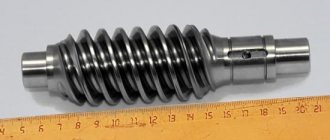
The equipment has great functionality, which allows you to perform various types of metal turning, including working with the following products:
- nuts;
- shafts of various configurations;
- bushings;
- rings;
- gears;
- couplings;
- pulleys.
The production of products using turning equipment involves obtaining high-quality products. Quality implies compliance with the specified shapes, sizes, location accuracy and degree of roughness of all surfaces of the finished product.
We recommend articles on metalworking
- Steel grades: classification and interpretation
- Aluminum grades and areas of their application
- Defects in metal products: causes and search methods
Electrical processing
Metalworking technology using electric charges involves processing the material using special equipment. They partially destroy metal workpieces.
Technological process:
- A high voltage is applied to an electrode made of graphite or brass.
- It comes into contact with the surface being treated.
- A spark appears and the metal begins to melt.
To prevent metal particles from scattering, special oil is poured into the space remaining between the electrode and the surface being treated. It traps metal particles.
8.1. Roughing
Roughing (sampling) is a preliminary operation that allows you to remove the main part of the material from the workpiece mass.
Roughing is done in planes parallel to the XY plane. The position of these planes along the Z axis (Sampling heights) can be set either manually or calculated according to a certain criterion (step, quantity, flatness condition, etc.). The distance between adjacent layers along the Z axis determines the thickness of the material removed by the cutter in one pass (cutting depth).
There are three options (strategies) for roughing:
· By profile
3D offset
| Strategy Raster - represents a set of passes parallel to the X or Y . | |
| Strategy By profile - represents a set of passes that repeat the profile of the part, in sections parallel to the XY (layers). | |
| Strategy 3D offset - processing is carried out equidistant to the section of the part until the material is completely removed . |
Click the Selection
on the Toolbar
.
The following window will appear:
For the roughing strategy, select the Offset
Parameter Step
determines the distance between adjacent tool passes within one layer. Let's set it equal to ¼ of the cutter diameter.
Allowance value
leave it at 1mm.
Parameter Tolerance
determines the accuracy with which the tool path will be calculated. Leave the Tolerance
equal to 0.1 mm.
Parameter Direction
determines the way the cutting edges of the tool are positioned relative to the part.
There are three options.
| Down milling Has the following advantages: · Less tool heating · Higher durability Better surface roughness Higher geometric accuracy | |
| Up milling Has the following advantages: · Less tool spin | |
| + | Any Combines both up and down milling |
Select Any
direction of movement of the cutter.
Let's set the sampling heights
(cutting depth).
Select Automatic method for calculating sample heights. Set the Z Step
equal to 8 mm (in one pass the cutter will remove a layer of material 8 mm thick).
Option Bypass profile
allows you to add an additional tool pass that describes the contour of the model with a specified allowance on each layer.
Remove the Finish Pass
. Profile Bypass function
we will use it for semi-finishing.
Before we receive a blank or finished metal product, it may go through several machines and units that will give it the desired shape.
The entire complex of work with a metal workpiece is called machining - during it, the workpiece is transformed into a finished product. If we take working with a complex product as an example, it must go through the following processing stages:
- roughing
(rough metalworking involves giving the workpiece a shape close to the shape of the finished product); - finishing
(the number of possible operations during finishing processing is noticeably greater).
Turning (boring) is a method of processing a workpiece with a metal single-edged tool.
Technological parameters:
- t = from 0.03-0.05 to 7-8 mm, sometimes t = 0.002-0.006 mm;
- S = 0.05-0.1 to 1.5-2 mm/rev; (see tables No. 1-5)
- V = from 1-2 to 150-1000 m/min; (see tables No. 6-8)
- cutting forces Pz = from 10-15 to 800-900 kgf.
Turning (boring) is carried out on machines :
- Lathes
- Revolver
- Boring
- Carousel
- Automatic and semi-automatic lathes (single- and multi-spindle) with horizontal and vertical spindles
- Multi-cutting lathes
- Automatic hydrocopying lathes
- and etc.
The achieved accuracy is from 14-13 qualifications (7-5th grade) to 9-7th qualification (3-2a grade). Under more careful processing conditions - up to 5-6th quality (1st-2nd grade).
Surface roughness from class 2-3 for roughing to class 5-6 for semi-finishing; with more careful processing, it is possible to achieve a roughness of 7-10 classes (Ra = 1.25 - 0.16 microns).
Dimensional accuracy and roughness of external cylindrical surfaces when processed on lathes
Type of processing
| Quality | Roughness parameters, microns | ||
| Rz | Ra | ||
| Turning: rough semi-finish finishing thin | 13-12 | 80…60 | — |
| 11-9 | 40…20 | — | |
| 8-7 | — | 2,5 | |
| 7-6 | — | 1,25…0,63 | |
| End cutting with a cutter: rough finishing thin | 12 | 40 | — |
| 11 | 20 | — | |
| 8-7 | — | 2,50…1,25 | |
Deviation from coaxiality of the surfaces of bodies of revolution processed on lathes
| Surface treatment method | Deviation from alignment, mm |
| In centers: from one installation from two installations | 0,008…0,004 |
| 0,015…0,008 | |
| On a mandrel: machined in place (on the same machine) when the deviation from the alignment of the mandrel, spindle and workpiece is no more than ±0.002 mm | 0,008…0,004 |
| 0,012…0,008 |
Types of turning and boring:
- Roughing t = up to 3-10 mm; S = 0.15-1.0 mm/rev; Processing accuracy: 12-14 quality (5-7 grade); Surface roughness: no higher than class 3 (Rz=80 µm); The deformed surface layer can reach a thickness of 0.5-0.9 mm. Scope of application: preliminary (rough) processing of workpieces, removal of the main part of the allowance, surface preparation for subsequent processing.
- Semi-finish t = 0.5-3 mm; S = 0.15-0.7 mm/rev; V = from 5-10 to 100-150 m/min Processing accuracy: 11-12 quality (4-3 class); Surface roughness: 4-6 class (Ra = 10-2.5 microns); Scope of application: preliminary and final surface treatment. Often precedes sanding.
- Finish t = 0.1-1.0 mm; S = 0.1-0.5 mm/rev; V = from 2-5 to 100-200 m/min and more; Processing accuracy: 11-7 quality (4-2a class); Surface roughness: 7-8 class (Ra = 1.25-0.63 microns); Scope of application: final surface treatment, as well as for preparing it for final processing by other methods (superfinishing, honing, lapping).
- Thin t = from 0.002-0.006 to 0.3 mm; S = 0.02-0.12 mm/rev; V = from 100 to 1000-6000 m/min; Processing accuracy: 9-5 quality (3-1 class); Surface roughness: 8-10 class (Ra = 0.63-0.16 µm); Scope of application: final surface treatment.
Table No. 1. Feeds during rough external turning with cutters with inserts made of carbide and high-speed steel.
| Part diameter, mm | Cutter holder size, mm | Processed material | |||||||||
| Structural carbon steel, alloyed and heat-resistant | Cast iron and copper alloys | ||||||||||
| Feed S, mm/rev, at cutting depth t, mm | |||||||||||
| Until 3 | St. 3 to 5 | St. 5 to 8 | St. 8 to 12 | St.12 | Until 3 | St. 3 to 5 | St. 5 to 8 | St. 8 to 12 | St. 12 | ||
| Up to 20 | From 16 x 25 to 25 x 25 | 0,3-0,4 | — | — | — | — | — | — | — | — | — |
| St. 20 to 40 | From 16 x 25 to 25 x 25 | 0,4-0,5 | 0,3-0,4 | — | — | — | 0,4-0,5 | — | — | — | — |
| » 40 » 60 | From 16 x 25 to 25 x 40 | 0,5-0,9 | 0,4-0,8 | 0,3-0,7 | — | — | 0,6-0,9 | 0,5-0,8 | 0,4-0,7 | — | — |
| » 60 » 100 | From 16 x 25 to 25 x 40 | 0,6-1,2 | 0,5-1,1 | 0,5-0,9 | 0,4-0,8 | — | 0,8-1,4 | 0,7-1,2 | 0,6-1,0 | 0,5-0,9 | — |
| » 100 » 400 | From 16 x 25 to 25 x 40 | 0,8-1,3 | 0,7-1,2 | 0,6-1,0 | 0,5-0,9 | — | 1,0-1,5 | 0,8-1,3 | 0,8-1,1 | 0,6-0,9 | — |
| » 400 » 500 | From 20 x 30 to 40 x 60 | 1,1-1,4 | 1,0-1,3 | 0,7-1,2 | 0,6-1,2 | 0,4-1,1 | 1,3-1,6 | 1,2-1,5 | 1,0-1,2 | 0,7-0,9 | — |
| » 500 » 600 | From 20 x 30 to 40 x 60 | 1,2-1,5 | 1,0-1,4 | 0,8-1,3 | 0,6-1,3 | 0,5-1,2 | 1,5-1,8 | 1,2-1,6 | 1,0-1,4 | 0,9-1,2 | 0,8-1,0 |
| » 600 » 1000 | From 25 x 40 to 40 x 60 | 1,2-1,8 | 1,1-1,5 | 0,9-1,4 | 0,8-1,4 | 0,7-1,3 | 1,5-2,0 | 1,3-1,8 | 1,0-1,4 | 1,0-1,3 | 0,9-1,2 |
| » 1000 » 2500 | From 30 x 45 to 40 x 60 | 1,3-2,0 | 1,3-1,8 | 1,2-1,6 | 1,1-1,5 | 1,0-1,5 | 1,6-2,4 | 1,6-2,0 | 1,4-1,8 | 1,3-1,7 | 1,2-1,7 |
Notes:
1. Lower feed values correspond to smaller cutter holder sizes and stronger processed materials, upper feed values correspond to larger cutter holder sizes and less durable processed materials.
2. When processing heat-resistant steels and alloys, do not use feeds exceeding 1 mm/rev.
3. When processing discontinuous surfaces and when working with impacts, the table feed values should be reduced by a factor of 0.75-0.85.
4. When processing hardened steels, reduce the table feed values by multiplying by a factor of 0.8 for steel with HRC 44-56 and by 0.5 for steel with HRC 57-62.
Table No. 2. Feeds during rough boring on lathes, turret lathes and rotary lathes with cutters with plates made of carbide and high-speed steel.
| Cutter or mandrel | Processed material | ||||||||||||
| Diameter of the circular cross-section of the cutter or dimensions of the rectangular cross-section of the mandrel, mm | Reach of cutter or mandrel, mm | Structural carbon steel, alloyed and heat-resistant | Cast iron and copper alloys | ||||||||||
| Feed S mm/rev, at cutting depth t, mm | |||||||||||||
| 2 | 3 | 5 | 8 | 12 | 20 | 2 | 3 | 5 | 8 | 12 | 20 | ||
| Lathes and turret lathes | |||||||||||||
| 10 | 50 | 0,08 | — | — | — | — | — | 0,12-0,16 | — | — | — | — | — |
| 12 | 60 | 0,10 | 0,08 | — | — | — | — | 0,12-0,20 | 0,12-0,18 | — | — | — | — |
| 16 | 80 | 0,1-0,2 | 0,15 | 0,1 | — | — | — | 0,2-0,3 | 0,15-0,25 | 0,1-0,18 | — | — | — |
| 20 | 100 | 0,25-0,3 | 0,15-0,25 | 0,12 | — | — | — | 0,3-0,4 | 0,25-0,35 | 0,12-0,25 | — | — | — |
| 25 | 125 | 0,25-0,5 | 0,15-0,4 | 0,12-0,2 | — | — | — | 0,4-0,6 | 0,3-0,5 | 0,25-0,35 | — | — | — |
| 30 | 150 | 0,4-0,7 | 0,2-0,5 | 0,12-0,3 | — | — | — | 0,5-0,8 | 0,4-0,6 | 0,25-0,45 | — | — | — |
| 40 | 200 | — | 0,25-0,6 | 0,15-0,4 | — | — | — | — | 0,6-0,8 | 0,3-0,8 | — | — | — |
| 40 x 40 | 150 | — | 0,6-1,0 | 0,5-0,7 | — | — | — | — | 0,7-1,2 | 0,5-0,9 | 0,4-0,5 | — | — |
| 300 | — | 0,4-0,7 | 0,3-0,6 | — | — | — | — | 0,6-0,9 | 0,4-0,7 | 0,3-0,4 | — | — | |
| 60 x 60 | 150 | — | 0,9-1,2 | 0,8-1,0 | 0,6-0,8 | — | — | — | 1,0-1,5 | 0,8-1,2 | 0,6-0,9 | — | — |
| 300 | — | 0,7-1,0 | 0,5-0,8 | 0,4-0,7 | — | — | — | 0,9-1,2 | 0,7-0,9 | 0,5-0,7 | — | — | |
| 75 x 75 | 300 | — | 0,9-1,3 | 0,8-1,1 | 0,7-0,9 | — | — | — | 1,1-1,6 | 0,9-1,3 | 0,7-1,0 | — | — |
| 500 | — | 0,7-1,0 | 0,6-0,9 | 0,5-0,7 | — | — | — | — | 0,7-1,1 | 0,6-0,8 | — | — | |
| 800 | — | — | 0,4-0,7 | — | — | — | — | — | 0,6-0,8 | — | — | — | |
| Carousel machines | |||||||||||||
| — | 200 | — | 1,3-1,7 | 1,2-1,5 | 1,1-1,3 | 0,9-1,2 | 0,8-1,0 | — | 1,5-2,0 | 1,4-2,0 | 1,2-1,6 | 1,0-1,4 | 0,9-1,2 |
| 300 | — | 1,2-1,4 | 1,0-1,3 | 0,9-1,1 | 0,8-1,0 | 0,6-0,8 | — | 1,4-1,8 | 1,2-1,7 | 1,0-1,3 | 0,8-1,1 | 0,7-0,9 | |
| 500 | — | 1,0-1,2 | 0,9-1,1 | 0,7-0,9 | 0,6-0,7 | 0,5-0,6 | — | 1,2-1,6 | 1,1-1,5 | 0,8-1,1 | 0,7-0,9 | 0,6-0,7 | |
| 700 | — | 0,8-1,0 | 0,7-0,8 | 0,5-0,6 | — | — | — | 1,0-1,4 | 0,9-1,2 | 0,7-0,9 | — | — | |
Notes:
1. Upper feed limits are recommended for shallower depths of cut when machining less durable materials, lower feeds are recommended for greater depths and stronger materials.
2. When processing heat-resistant steels and alloys, do not use feeds exceeding 1 mm/rev.
3. When processing discontinuous surfaces and when working with impacts, the table feed values should be reduced by a factor of 0.75-0.85.
4. When processing hardened steels, reduce the table feed values by multiplying by a factor of 0.8 for steel with HRC 44-56 and by 0.5 for steel with HRC 57-62.
Table No. 3. Feeds, mm/rev, for finishing turning.
| Surface roughness parameter, µm | Radius at the tip of the cutter r, mm | ||||||
| 0,4 | 0,8 | 1,2 | 1,6 | 2,0 | 2,4 | ||
| Ra | Rz | ||||||
| 0,63 | — | 0,07 | 0,10 | 0,12 | 0,14 | 0,15 | 0,17 |
| 1,25 | — | 0,10 | 0,13 | 0,165 | 0,19 | 0,21 | 0,23 |
| 2,50 | — | 0,144 | 0,20 | 0,246 | 0,29 | 0,32 | 0,35 |
| — | 20 | 0,25 | 0,33 | 0,42 | 0,49 | 0,55 | 0,60 |
| — | 40 | 0,35 | 0,51 | 0,63 | 0,72 | 0,80 | 0,87 |
| — | 80 | 0,47 | 0,66 | 0,81 | 0,94 | 1,04 | 1,14 |
Note:
1. Feeds are given for processing steels with σВ=700÷900 MPa and cast irons; for steels with σВ=500÷700 MPa, multiply the feed value by the coefficient KS=0.45; for steels with σВ=900÷1100 MPa, feed values are multiplied by the coefficient KS=1.25.
Table No. 4. Feeds, mm/rev, when cutting grooves and cutting.
| Processing diameter, mm | Cutter width, mm | Processed material | |
| Structural carbon and alloy steel, cast steel | Cast iron, copper and aluminum alloys | ||
| Turret lathes | |||
| Up to 20 | 3 | 0,06-0,08 | 0,11-0,14 |
| St. 20 to 40 | 3-4 | 0,10-0,12 | 0,16-0,19 |
| » 40 » 60 | 4-5 | 0,13-0,16 | 0,20-0,24 |
| » 60 » 100 | 5-8 | 0,16-0,23 | 0,24-0,32 |
| » 100 » 150 | 6-10 | 0,18-0,26 | 0,30-0,40 |
| » 150 | 10-15 | 0,28-0,36 | 0,40-0,55 |
| Carousel machines | |||
| Up to 2500 | 10-15 | 0,35-0,45 | 0,55-0,60 |
| St. 2500 | 16-20 | 0,45-0,60 | 0,60-0,70 |
Notes:
1. When cutting solid material with a diameter of more than 60 mm, when the cutter approaches the axis of the part up to 0.5 radius, the table feed values should be reduced by 40-50%.
2. For hardened structural steel, reduce the table feed values by 30% for HRC < 50 and by 50% for HRC > 50.
3. When working with cutters installed in the turret head, multiply the table values by a factor of 0.8.
Table No. 5. Feeds, mm/rev, for shaped turning.
| Cutter width, mm | Processing diameter, mm | |||
| 20 | 25 | 40 | 60 or more | |
| 8 | 0,03-0,09 | 0,04-0,09 | 0,04-0,09 | 0,04-0,09 |
| 10 | 0,03-0,07 | 0,04-0,085 | 0,04-0,085 | 0,04-0,085 |
| 15 | 0,02-0,05 | 0,035-0,075 | 0,04-0,08 | 0,04-0,08 |
| 20 | — | 0,03-0,06 | 0,04-0,08 | 0,04-0,08 |
| 30 | — | — | 0,035-0,07 | 0,035-0,07 |
| 40 | — | — | 0,03-0,06 | 0,03-0,06 |
| 50 or more | — | — | — | 0,025-0,055 |
Note:
1. Use smaller feeds for more complex and deep profiles and hard metals, larger feeds for simple profiles and soft metals.
Table 6. Cutting conditions for fine turning and boring.
| Processed material | Material of the working part of the cutting tool | Surface roughness parameter Ra, µm | Feed, mm/rev | Cutting speed, mm/min |
| Steel: σВ < 650 MPa | T30K4 | 1,25-0,63 | 0,06-0,12 | 250-300 |
| Steel: σВ = 650÷800 MPa | 150-200 | |||
| Steel: σB > 800 MPa | 120-170 | |||
| Cast iron: HB 149-163 | VK3 | 2,5-1,25 | 150-200 | |
| Cast iron: HB 156-229 | 120-150 | |||
| Cast iron: HB 170-241 | 100-120 | |||
| Aluminum alloys and babbitt | 1,25-0,32 | 0,04-0,1 | 300-600 | |
| Bronze and brass | 0,04-0,08 | 180-500 |
Notes:
1. Cutting depth 0.1-0.15 mm.
2. A preliminary pass with a cutting depth of 0.4 mm improves the geometric shape of the machined surface.
3. Smaller values of the surface roughness parameter correspond to smaller feeds.
Table 7. Cutting conditions when turning hardened steel with cutters with carbide inserts.
| Feed S, mm/rev | Cutting width, mm | Hardness of the processed material HRC | |||||||||
| 35 | 39 | 43 | 46 | 49 | 51 | 53 | 56 | 59 | 62 | ||
| Cutting speed V, m/min | |||||||||||
| External longitudinal turning | |||||||||||
| 0,2 | — | 157 | 135 | 116 | 107 | 83 | 76 | 66 | 48 | 32 | 26 |
| 0,3 | — | 140 | 118 | 100 | 92 | 70 | 66 | 54 | 39 | 25 | 20 |
| 0,4 | — | 125 | 104 | 88 | 78 | 60 | 66 | 45 | 33 | — | — |
| 0,5 | — | 116 | 95 | 79 | 71 | 53 | — | — | — | — | — |
| 0,6 | — | 108 | 88 | 73 | 64 | 48 | — | — | — | — | — |
| Grooving | |||||||||||
| 0,05 | 3 | 131 | 110 | 95 | 83 | 70 | 61 | 54 | 46 | 38 | 29 |
| 0,08 | 4 | 89 | 75 | 65 | 56 | 47 | 41 | 37 | 31 | 25 | 19 |
| 0,12 | 6 | 65 | 55 | 47 | 41 | 35 | 30 | 27 | 23 | 18 | 14 |
| 0,16 | 8 | 51 | 43 | 37 | 32 | 27 | 23 | — | — | — | — |
| 0,20 | 12 | 43 | 36 | 31 | 27 | 23 | 20 | — | — | — | — |
Notes:
1. Depending on the cutting depth, enter a correction factor for the table value of cutting speed: 1.15 at t=0.4÷0.9 mm; 1.0 at t=1÷2 mm and 0.91 at t=2÷3 mm
2. Depending on the roughness parameter, enter a correction factor for the table value of cutting speed: 1.0 for Rz=10 µm; 0.9 for Ra=2.5 µm and 0.7 for Ra=1.25 µm.
3. Depending on the grade of carbide, enter the correction factor KIV :
| Hardness of the processed material | HRC 35-49 | HRC 50-62 | |||||
| Carbide grade | T30K4 | T15K6 | VK6 | VK8 | VK4 | VK6 | VK8 |
| KIV coefficient | 1,25 | 1,0 | 0,85 | 0,83 | 1,0 | 0,92 | 0,74 |
Table 8. Cutting conditions when turning and boring with cutters equipped with a boron nitride-based composite.
| Processed material | Nature of processing | Composite grade | Depth of cut t, mm | Feed S, mm/rev | Cutting speed V, m/min |
| Hardened steel, HRC 40-58 | Without hitting | 01; 05 | 0,05-3,00 | 0,03-0,2 | 50-160 |
| With a bang | 10; 10D | 0,05-1,0 | 0,03-0,1 | 40-120 | |
| Hardened steel, HRC 58-68 | Without hitting | 01 | 0,05-0,8 | 0,03-0,1 | 50-120 |
| With a bang | 10; 10D | 0,05-0,2 | 0,03-0,07 | 10-100 | |
| Gray ductile iron, HB 150-300 | Without hitting | 05; 01 | 0,05-3,0 | 0,05-0,3 | 300-1000 |
| With a bang | 10; 10D; 05; 01 | 0,05-3,0 | 0,05-0,15 | 300-700 | |
| Whitened hardened cast iron, HB 400-600 | Without hitting | 05; 01 | 0,05-2,0 | 0,03-0,15 | 80-200 |
| With a bang | 10; 10D | 0,05-1,0 | 0,03-0,10 | 50-100 | |
| Hard alloys VK15, VK20, VK 25, etc., HRA 80-86 | No impact, runout allowed | 10; 10D; 01 | 0,05-1,0 | 0,03-0,10 | 5-20 |
Pressure treatment
If mechanical types of metal processing are not suitable and it is necessary to maintain the integrity of the workpiece, craftsmen can use equipment that works with pressure. Technological processes in this case are divided into two groups:
- Stamping. This method uses two key elements - a punch and a die. The workpiece being processed is placed between these parts. Then, with the help of force, it moves. The workpiece takes the form of a matrix. There is hot and cold stamping. In the first option, the part is initially heated.
- Forging. In ancient times, blacksmiths forged weapons and armor. To do this, the workpiece was heated in a forge, and after that it was struck with a hammer. This changes the structure of the material and improves its characteristics.
Nowadays, forging uses pneumatic hammers and industrial furnaces.
Scheme of processing on a lathe
To launch a new series of products at any enterprise, schematic images are developed that play the role of technical specifications for turners. They make it possible to greatly simplify and save time on metal work, since the craftsman does not have to independently select the mode, speed, and required cutter. The circuits are first checked to avoid various defects. This also allows you to calculate more accurate product parameters, which is especially important for serial turning production.
The diagram shows:
- method of fixing the cutter;
- its position in relation to the workpiece;
- turning process using symbols.
It presents the main parameters, which can be adjusted if necessary to achieve maximum precision in processing parts.
How to become a metalworking professional
Training in turning, as, for example, in the profession of a doctor, lasts a whole life, in addition to a significant amount of theoretical information, books and practical skills that need to be mastered, there is a constantly updated fleet of equipment that requires study, lathes are developing. The range of processed materials is also increasing, and new composite and polymer materials with unstudied properties are appearing.
Lessons in turning and metal processing from more experienced colleagues and teachers can help in mastering the profession. Now a library of technical literature on metal processing has become available on the Internet: reference books, turner’s manuals and textbooks. Additional education requires time, which is always in short supply, and money, which will also not be superfluous, but these costs will more than pay off in the future.
https://youtube.com/watch?v=qEHIrxF013k
Pressure treatment
If mechanical types of metal processing are not suitable and it is necessary to maintain the integrity of the workpiece, craftsmen can use equipment that works with pressure. Technological processes in this case are divided into two groups:
- Stamping. This method uses two key elements - a punch and a die. The workpiece being processed is placed between these parts. Then, with the help of force, it moves. The workpiece takes the form of a matrix. There is hot and cold stamping. In the first option, the part is initially heated.
- Forging. In ancient times, blacksmiths forged weapons and armor. To do this, the workpiece was heated in a forge, and after that it was struck with a hammer. This changes the structure of the material and improves its characteristics.
Nowadays, forging uses pneumatic hammers and industrial furnaces.
Standard hour cost
The cost of a standard hour in our company starts from 850 rubles, but in the end, it is always determined depending on the volume, complexity and required production speed.
| Kind of work | Price with VAT |
| Creating a 3D model from a drawing | from 1,000 rub. / hour |
| Technology development and tool selection | from 600 rub. / hour |
| Writing control programs | from 1,200 rub. / hour |
| Turning on universal machines | from 850 rub. / hour |
| Turning on CNC machines | from 1,100 rub. / hour |
| Urgent turning work | from 2,000 rub. / hour |
| Turning work with hard alloys (tungsten-cobalt, titanium-tungsten-cobalt, titanium-tantalum-tungsten-cobalt) | individually |
| Turning for materials up to HRC 45 | from 1,300 rub. / hour |
electroplating
Scope of application and features
Processing materials on a lathe involves securing a cylindrical workpiece into a three-jaw chuck. Due to the perpendicular feed of the cutting tool, the specified thickness of the metal is removed. All this allows you to grind the workpiece to the required size.
When performing certain jobs, simply fixing the workpiece in the chuck is not enough. To ensure safety, obtain the required cleanliness and accuracy, additional support of the part by the tailstock is required.
In what cases is it necessary to use a rotating center:
- The length of the workpiece is 5 times the diameter.
- Turning of heavy parts at high speeds (high speed and feed).
- Large thickness of chips removed.
- When finishing will take place on a grinding machine.
Features and benefits of using centers:
- Long service life.
- Resistance to high loads.
- Possibility to increase processing speed.
- Improving equipment performance.
- Versatility - can be used on manual machines and CNC equipment.
- High quality parts.
You might also be wondering how to properly mount a DRO on a lathe?
The disadvantages of the device include radial runout. If, according to technical requirements, this error is unacceptable, finishing is practiced using a fixed center in gentle modes.
Features of artistic processing
The basics of metalworking include not only changing the shape and size of the workpiece, but also their decorative processing. The master can create individual products, or decorate ready-made metal structures. There are 4 metalworking processes that allow you to change the appearance of a part:
- casting;
- forging;
- minting;
- welding.
All types of decorative work with metal involve initial heating of the workpiece. The higher the plasticity, the easier it is to work with parts.
Welding technology is considered new compared to others. Its active development begins in the second half of the 20th century. Using a welding machine, you can cut metal sheets and connect the parts together.
Metal is a hard material, when working with it you need to use special equipment and heat the workpiece. Processing allows you to change the size and shape of a part, as well as improve its technical characteristics. Using methods of decorative work with material, you can decorate products, improving their appearance.
Mechanical restoration
There are various types of mechanical processing of metals. This is the largest group of material processing methods that use special tools and equipment. Mechanical force allows you to remove a layer of metal from the workpiece.
Mechanical restoration
Drilling and turning
Drilling is the processing of metals using special equipment. Drilling technology is divided into several stages:
- The workpiece is secured to the work table using clamps or a vice.
- An accessory is fixed in the working tool chuck - a drill or a sword for cutting threads.
- After turning on the electric motor, the spindle spins the chuck. The equipment makes a hole of the required diameter in a metal workpiece.
When choosing equipment, it is necessary to take into account the characteristics of the material being processed. Drills can withstand different loads.
Another common type of metal machining is turning. Using this technological process, cylindrical and cone-shaped parts are created. Drilling method:
- The workpiece is fixed in a movable spindle.
- After turning on the engine, it spins the workpiece.
- The master brings the cutters to remove the layer of metal.
Grinding and milling
Another popular method of metal processing is milling. It looks like drilling. Using a cutter, you can make various recesses in metal surfaces, create threads, and process the ends of workpieces. When the spindle rotates, the equipment removes a layer of metal.
Abrasive materials are also used in the processing of metal and wood. The coated circle is fixed on a movable shaft, which is spun by an electric motor. The type of processing depends on the choice of abrasive fraction. To clean a surface from a thick layer of rust or metal, you need to use abrasive wheels with large particles. A fine fraction is suitable for finishing work.
Grinding processing
Basic turning operations and cutters used
- tailstock O
mounted on the right side of the frame and can be manually moved along its internal guides.
The tailstock serves: a
) to support long workpieces in the centers during processing;
b
) turning cones by shifting the tailstock body relative to the frame guides by rotating bolt 18;
c
) securing tools for processing holes (drills, countersinks, reamers, taps, etc.);
— in the lower part of the frame there is a trough 20 to collect chips and drain coolant from the cutting zone. The cooling liquid flows from the trough along the riser 21 into the emulsion tank 22, from there it is supplied to the cutting zone through pipelines by an electric pump located in the right cabinet. The machine is turned on by handle 19. Under the removable casing E
accommodates guitar replacement gears
2.3. Kinematic diagram of the machine [1]
The kinematic diagram of the IM6I machine includes a main movement chain, a screw-cutting chain, as well as longitudinal and transverse feed chains.
Main movement chain. The main movement of a screw-cutting lathe is the rotational movement of the spindle I (see Fig. 1.2). The movement from the electric motor M (see Fig. 1.3) through a V-belt transmission with pulleys 2 and 17 is transmitted to the input shaft I
speed boxes.
On shaft I
there are two double blocks of gears B1 with wheels 18, 19 and B2 with wheels 22, 23, which, by alternately engaging with wheels 16, 20, 21, 24, rigidly seated on shaft
II
, provide it with four different rotation speeds. On the same shaft there is a triple block of gears
Rice. 1. 3. Kinematic diagram of the 1M61 screw-cutting lathe
B3 with wheels 25, 26 and 27, giving through sequential engagement with wheels 38, 37, 28 to shaft III
12 different rotation speeds.
The machine spindle (shaft V
) has 24 rotation speeds.
Twelve of them are obtained with the M1 clutch engaged. In this case, transmission from shaft III
to shaft
V
is carried out by transmission
z
30
/ z
36. The moving part of the coupling M1, made integral with gears 30 and 33, rotates freely on the gear housing 32. Twelve lower rotation speeds are transmitted to the spindle when the clutch is turned off M1 (position shown in Fig. 1.3) through the enumeration mechanism.
The selection mechanism includes gears 29, 30, 31, 33, 35. When clutch M1 is turned off, the spindle receives rotation from gear 32, located at the right end of shaft III
, through wheels 31 and 29 of shaft
IV
and gearing
z
29
/z
30
∙z
33
/z
35. The kinematic balance equation of the main motion chain has the form:
| . | . |
| = nob.shp ., (1) | |
| · |
where n
about. e. d. – number of revolutions of the electric motor shaft in min.;
n
sp – number of spindle revolutions per minute.
Reversing (changing the direction of rotation) of the spindle is carried out by an electric motor by turning handle 19 down (see Fig. 1.2).
Feed chain. The feed chain on screw-cutting lathes connects the rotation of the spindle (workpiece) with the movement of the support (tool) and allows you to obtain different values of longitudinal and transverse feeds, as well as cut threads with a cutter with different pitches. To carry out the feeding and threading movements, shaft VI
receives rotation from the spindle through the gear
z
15
/z
11 or from shaft
III
through the link for increasing the thread pitch by means of engagement
z
39
/z
12. From shaft
VI
, the movement is transmitted to shaft
VIII
directly through engagement
z
13
/z
8 or through reverse[4] feed
z
14
/z
10
∙z
9
/z
8 used when cutting left-hand threads.
Next, the movement is transmitted to the input shaft IX
of the feed box through a set of interchangeable gears
a
,
b
,
c
.
The link for increasing the thread pitch includes a z
39
/ z
12 gear and is used only when the override mechanism is turned on (the M1 clutch is turned to the right) to obtain threads with an increased pitch and when cutting multi-start threads.
In this case, the thread pitch, compared to transmission through z
15
/ z
11, increases 16 times.
Let's consider the feed circuit of the machine in the case when couplings M2, M3, M5 (as shown in the diagram) are turned on. In this case, shaft IX
, on which the wheel “
c
” of the guitar of interchangeable gears is located, is directly connected by coupling M2 to shaft
X
and the movement is transmitted directly to shaft
XII
through gears 40, 41, 43 and 45, rigidly mounted on shaft
X
, and two double blocks of gears B6 and B7, respectively, with wheels 3, 4 and 79, 42. Since the M5 clutch is engaged, rotation is transmitted to the gear block B8 of shaft
XIII
.
Using this block, by engaging wheels 73/47 and 74/48, with the M3 clutch engaged on the XI
, eight different rotation speeds can be obtained.
Gear ratio of the feedbox i
to
.
when clutches M2, M3, M5 are engaged, are determined by the relation
| · | · (2) |
| i kp = |
The equation for the kinematic balance of a screw-cutting chain has the form:
| (right) | ||
| 1 rev.sp. · | · | ∙ iг ∙ iк.п. ∙ tх.в=Т, mm (3) |
| ∙ ∙ ∙ | ∙ (left) |
where iг
,
ic.p.
— gear ratios of the replacement gears and gearbox;
th.v. —
lead screw pitch, mm (item 56, Fig. 1.3);
T—
pitch of cut thread, mm.
Guitar gear ratio of replacement gears iг
when performing all turning operations, as well as when cutting metric and inch threads, it is determined by the ratio:
ig
= , (4),
and when cutting modular and pitch threads:
ig
= . (5)
When cutting threads, rotation of the running shaft 56 from shaft XI
transmitted by turning on the M4 clutch.
To carry out longitudinal and transverse feeds, rotation from shaft XI
to the running shaft
XIV
of the apron mechanism through the
z
49
/ z
76 gear with the M4 clutch disengaged.
Equation of kinematic balance of the chain for longitudinal S
etc. and cross feeds
S
pop. has the form:
| 1ob.shp . ∙ ∙ ∙ ∙ ∙ ∙ ∙ · |
| (6) |
where t
— rack and pinion wheel module;
th.v.
— pitch of the cross-feed screw in mm (pos. 75
rice. 1.3).
⇐ Previous2Next ⇒
Recommended pages:
How can metal be processed by cutting?
Cutting processing can be carried out using several methods. They are focused on products of different shapes and have different purposes. The main methods of metal cutting:
- Turning. It is performed using a machine on which a cutter is installed (for example, a lathe). The work process looks like this: the workpiece undergoes a rotational movement around its axis, and at this time the required layer of metal is removed with a cutter. Turning is used for cylindrical, conical and end surfaces (both external and internal).
- Drilling. Performed on machines with a drill installed. It is easy to guess that drilling is intended to make holes in parts. The part is firmly clamped in a vice, and a hole of the required diameter is drilled into it, the diameter being determined by the size of the drill. Meanwhile, drills differ not only in size, but also in shape: there are twist drills, feather drills, centering drills and others, each for its own purposes.
- Milling. Requires special equipment on which a milling cutter is installed - a tool with cutters. The cutter makes a rotational movement, and the workpiece, fixed on the table, moves longitudinally. Milling can be horizontal, vertical and diagonal, depending on how the workpiece and the cutter are secured. There are also compact manual electric milling cutters, which, if necessary, can be used anywhere without tying the master to the machine. True, they have much less opportunities.
- Planing. It requires a planing machine (there are several types: planer-slotting, cross-planing, longitudinal-planing, etc.). They mainly process frames, rods, beds, etc. Cutters can be used straight or curved. Direct ones are the easiest to use, but do not allow achieving high accuracy. Curved cutters are highly accurate and are therefore preferred and more common.
- Chiseling. A slotting machine is required. The cutter makes a rectilinear reciprocating movement, and the workpiece moves perpendicular to it. Mostly used for flat surfaces with low height. Using chiselling, for example, you can obtain gears with quite good degrees of accuracy.
- Grinding. It requires a machine with a grinding wheel. The grinding wheel rotates, and the workpiece receives a circular, longitudinal or transverse feed. Grinding allows you to obtain a part of amazing precision; you just need to take into account a number of features of the process, such as heating the part during processing, stability of the machine (absence of strong vibrations), depth of cut, etc.
Process Features
A distinctive feature of metal turning is the rotation of the workpiece and the stationary fastening of the cutter. This allows the production of shafts and other parts with a large number of cylindrical and conical surfaces.
Turning is a high-performance mechanical processing that provides high dimensional accuracy and good interaction of mating parts.
Processing modes
The metal processed by turning has various qualities: hardness, toughness, ductility. They all require different cutting angles and cutting speeds. Before issuing drawings for work, technologists make calculations of cutting conditions during turning. Based on them, normalization is made according to the time spent on performing each operation. Cutting modes include:
- spindle rotation speed;
- cutting depth;
- innings.
Quality and processing speed are opposite indicators when turning. They depend on the depth of cut and tool feed. The more chips removed in one pass, the greater the dimensional error and surface roughness.
Initially, rough turning is done - a large layer of metal is removed with a through cutter with an edge forming an acute angle to the axis of rotation of the workpiece. Then a tool with a large contact area is placed on the surface to be processed and finishing is done - a thin layer of metal is removed with the side edge of the cutter and at the same time the ridges are smoothed with an edge located along the axis of the workpiece.
The softer the metal, the smaller the sharpening angle - the sharper the cutter. Cast iron and high alloy steels are processed with square plates. For aluminum and bronze, sharpening is done at 30⁰.
Turning technology
When processing on lathes, the cutter, moving along the workpiece, cuts into its surface. The cutting edge separates a narrow strip of metal - chips. The width and thickness of the chips are set by the machine operator.
Processing technology makes it possible to produce shafts with a large number of transitions and sizes. Moreover, all cylinders and cones are coaxial, since they were machined from the same installation. End drilling and other processing are done without reinstalling the part. The stationary tool is rigidly fixed, which allows the processing speed to be increased several times.
Introduction of CNC
A significant breakthrough in the field of machine tool building was the use of the Numerical Program Control system. With the advent of the CNC system, products can now be obtained at lower costs; the cleanliness of processing, as well as accuracy, are at the highest level.
The presence of a CNC system determines the following:
- increased productivity when the cutters are used with a carbide cutting edge;
- processing of both ferrous and non-ferrous, as well as tool alloys is possible with appropriate equipment;
- The intervention of the master in the process is minimal. cutting occurs automatically;
- The CNC system allows you to specify all cutting modes. the CNC program is compiled indicating the speed at which cutting is carried out, as well as the feed;
- often the entire area in which cutting occurs is covered with a protective casing, since the CNC system will not allow you to start working without protecting others;
- the high precision of CNC operation, which is obtained by cutting with the correct speed, allows you to obtain parts with a lower rate of defects for critical elements of various structures.
The CNC system is widely used in the production of lathes in China and the USA. The possibility of implementing CNC is determined by the accuracy of positioning of machine design elements.
Chemical and mechanical treatment
Thermal methods are used using chemistry to saturate the metal with elements, such as carbon. This method of exposure is called chemical-thermal. And if the product is mechanically affected during the cooling process, giving it the desired shape, then this is thermomechanical processing.
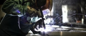
Welding
Strong connection of two or more metal parts to each other.
When welding, the product is heated at the site of the intended seam until it melts. The atoms of the parts being joined are then mixed, forming a seam as they cool.
Under normal conditions, it is impossible to connect parts by squeezing them together; the fact is that the surface of the metal is contaminated with various substances. When the material heats up and melts, fresh layers of metal are released, so their connection becomes possible.
There are three types of welding:
- thermal,
- thermomechanical,
- mechanical.
Thermal or thermal effects on parts involve heating without the application of additional pressure. Heat is obtained from an electric arc (electrical effect), gas flame.
With thermomechanical joining, the parts are heated only to the point of their plasticity, after which they are tightly connected, squeezing each other.
Pressure welding deforms the metal to such an extent that it begins to flow like water.
Pressure Welding
The contaminated layers drain away, revealing a fresh layer. A chemical reaction then begins, joining the parts together.
This process occurs only with the use of automation. A person does not have sufficient strength to lead to such reactions. This welding is applicable when you need to connect large parts with thick walls.
Manual welding
In everyday life, portable welding machines are more often used, capable of welding structures made of metals of small thickness. The principle of electric arc is used here.
Using a special electrode, a short circuit is caused to the workpiece being welded. A stable arc discharge of about 6 thousand degrees Celsius occurs. Then, at a distance of 2–5 millimeters between the electrode and the product, the welding process occurs. The result is a strong seam that can withstand great external pressure.
Submerged arc welding
In production conditions, automatic submerged arc welding is used.
Submerged Arc Welding Process
It is poured onto the products to be welded in a layer of 50–60 millimeters. Then start welding.
First, the flux itself is heated, and welding occurs in the flux gas environment, while the metal itself is not exposed to oxygen. The seam of such welding is stronger than manual welding.
Pressure treatment
To give the future product the desired shape, during the manufacture of semi-finished products and parts, pressure is applied to it. In this case, the properties of the material do not change, only the shape changes.
There are the following methods of applying pressure:
- forging,
- stamping,
- sheet stamping,
- rolling,
- pressing,
- drawing.
Forging
The oldest processing method is forging. The metal is heated to a plastic state, after which it is given the desired shape using special tools. In ancient times, blacksmiths used forging to make weapons, tools, and tools. Nowadays forging is used more in architecture, when creating patterns for gates and staircase handrails.
Forging is also possible without preheating. The desired shape is given by bending it in a certain way. With this method, additional processing of the metal will be necessary, because errors in the work appear.
Stamping
Automated process using machines. The future part is either placed in a special mold, after which it is subjected to pressure, or it is impacted with a stamp of a given shape. In the first case, three-dimensional products are obtained, in the second, sheet metal is used.
When rolling, the metal is passed between two rotating rollers. The output is smooth sheets. The drawing process is similar to rolling, however, the result is not sheets, but wire. The combined effect of pressure on the metal is also used.
Electrical processing
One of the last stages of processing.
This metal processing is used for particularly hard alloys that require jewelry work and cannot be treated by other means. All stages of the process are carried out scrupulously, maintaining the necessary conditions to obtain high-quality material.
Electrical processing is also used to cut out small holes and notches in the product, and make engravings.
Advanced Metalworking Techniques
Metalworking technology is a set of technological processes by which blacksmiths change the characteristics, shape, and dimensions of metals and alloys. To make people's work easier, machines are constantly being improved. They are equipped with additional modules that expand the functionality. The machines are equipped with CNC systems.
The developers of new mechanisms are aimed at achieving three goals:
- Increased accuracy of moving elements.
- Reliability in active use. Developments are aimed at producing more durable equipment that can work longer and more efficiently.
- Productivity - the speed of operations performed by moving mechanisms increases the quantity of finished products.
Installing additional spindles, working parts, and CNC systems increases the productivity, accuracy, and efficiency of industrial machines.
Introduction of CNC
A significant breakthrough in the field of machine tool building was the use of the Numerical Program Control system. With the advent of the CNC system, products can now be obtained at lower costs; the cleanliness of processing, as well as accuracy, are at the highest level.
The presence of a CNC system determines the following:
- increased productivity when the cutters are used with a carbide cutting edge;
- processing of both ferrous and non-ferrous, as well as tool alloys is possible with appropriate equipment;
- The intervention of the master in the process is minimal. cutting occurs automatically;
- The CNC system allows you to specify all cutting modes. the CNC program is compiled indicating the speed at which cutting is carried out, as well as the feed;
- often the entire area in which cutting occurs is covered with a protective casing, since the CNC system will not allow you to start working without protecting others;
- the high precision of CNC operation, which is obtained by cutting with the correct speed, allows you to obtain parts with a lower rate of defects for critical elements of various structures.
The CNC system is widely used in the production of lathes in China and the USA. The possibility of implementing CNC is determined by the accuracy of positioning of machine design elements.
Safety precautions when turning metal
Certain safety precautions must be observed when performing operations on turning equipment. Otherwise, you can damage the product, break the cutter, or get injured:
- We must not forget about protective work clothing. The kit should include: a robe, a headdress, fully closed shoes, and safety glasses. Neglect of equipment can lead to burns and wounds from chips and flying metal fragments.
- You cannot work with gloves!
- The cutters must be well sharpened and, when using a lathe, centered and secured.
- You need to hold the chisels firmly with both hands when working with them.
- It is imperative to rough the workpiece before shaping it.
- You cannot be distracted and leave the working machine unattended.
- You shouldn’t rush, you need to correctly calculate your strength when feeding manually.
Working metal on a lathe requires practice. Each new machine must be mastered, and different operations must be tried on defective workpieces. This will provide an opportunity to understand the characteristics of the equipment, gain greater accuracy and achieve increased productivity. By following the recommendations listed above, you can get excellent results and also avoid defects and injuries.
Features of metal processing
Metals consisting of different components have their own strength and flexibility indicators and other characteristics. They cannot be processed in the same ways. When choosing a method of influencing a material, the requirements for the product to be obtained are taken into account. Sometimes it is necessary to change not only the shape, but also the technical characteristics of the alloy.
There are 5 ways to process metal workpieces:
- mechanical;
- chemical;
- electric;
- thermal;
- exposure to pressure.
Using tools designed for mechanical work, you can cut a part, make a hole in it, and polish it. Often the result is a rough workpiece, which is additionally subjected to pressure and high temperatures.
Processing of hard steel grades is carried out electrically. It is also used if you need to make holes of different shapes and sizes in metal and sharpen tools. This method involves the use of different types of machines.
Chemical treatment is the effect on the workpiece of various compounds (acids, alkalis) that react with the metal alloy. After the interaction is completed, the physical and chemical characteristics of the metal change. Their improvement is often the point of impact.
During heat treatment, as with chemical treatment, the performance properties of the workpiece are improved and its strength increases.
You can change the shape of a part without compromising its integrity using high pressure. When working with hard metals (some grades of steel, for example), the workpiece is preheated.
Features of artistic processing
The basics of metalworking include not only changing the shape and size of the workpiece, but also their decorative processing. The master can create individual products, or decorate ready-made metal structures. There are 4 metalworking processes that allow you to change the appearance of a part:
- casting;
- forging;
- minting;
- welding.
All types of decorative work with metal involve initial heating of the workpiece. The higher the plasticity, the easier it is to work with parts.
Welding technology is considered new compared to others. Its active development begins in the second half of the 20th century. Using a welding machine, you can cut metal sheets and connect the parts together.
Metal is a hard material, when working with it you need to use special equipment and heat the workpiece. Processing allows you to change the size and shape of a part, as well as improve its technical characteristics. Using methods of decorative work with material, you can decorate products, improving their appearance.
Work technology
Lathes are designed for processing bodies of rotation. The following work is performed on this equipment:
- End trimming;
- Turning of external surfaces;
- Thread cutting of any type;
- Cutting off parts;
- Application of corrugations;
- Drilling and boring internal holes.
However, this is not the only thing that can be done on this machine. In addition, it can be used for polishing and lapping holes. Polishing can be performed using a special felt wheel and GOI paste. With their help, the product acquires a mirror surface, but the accuracy of the surface is not ensured. The surface of the hole is fine-tuned using a lap. This operation allows you to obtain an accurate hole with a low roughness index.
The tool can be fixed in the spindle or in centers. Centers are special devices that are fixed in the spindle and tailstock. To ensure this, it is necessary to first center (drill a hole in the axis with a special drill) the workpiece on both sides. The center machining setup allows all transitions to be completed in one setup.
Specifics of operation
Before starting work, the turner must take into account runout errors. It occurs due to wear of the bearings or tip, or insufficiently rigid fixation. If the requirements do not allow such an error, it is better to use other equipment.
What nuances need to be taken into account when processing in centers:
- The axes of the spindle and center must coincide, otherwise there will be processing errors. When turning parts with a high accuracy class, allowances must be left for finishing.
- The clamping force should securely fix the workpiece, but not interfere with its rotation.
- When working at high speeds, lubricant must be used to reduce tip wear.
Important!
The runout of the rotating center leads to radial runout of the part relative to the axis. Further processing of the same workpiece on another machine may lead to misalignment.
If strong runout is detected, the conical tip must be ground with a special tool, which is attached to the tool holder. After checking with a template, if the result is satisfactory, you can begin metalworking.
Important!
When turning at high speeds, the center tip wears out and the center hole breaks. To extend the life of the equipment, the tip is treated with a protective lubricant.