We recommend purchasing:
Installations for automatic welding of longitudinal seams of shells - in stock!
High performance, convenience, ease of operation and reliability in operation.
Welding screens and protective curtains are in stock!
Radiation protection when welding and cutting. Big choice. Delivery throughout Russia!
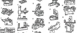
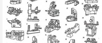
Processing methods and tools used
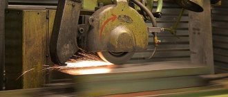
Turning of shaped surfaces is carried out on lathes or milling machines. There are several basic processing methods:
- using manual and automatic feeding of through cutters using a caliper;
- through shaped cutters;
- using copying equipment and devices.
Using through cutters, a small number of shaped workpieces are turned. The location of the cutting edges and the shape of the tip of the cutter are selected in accordance with the angles of inclination and the radius of the product. Turning is carried out through simultaneous longitudinal and transverse movement of the cutter. If you have no experience, it is recommended to perform the following exercise to practice these maneuvers: a workpiece with a shaped surface and a complex profile is installed in centers or chucks; a person must correctly move the support so that the top of the cutting tool is at a close distance from the surface of the workpiece.
After acquiring the necessary turning skills on lathes, you can carry out complex processing of shaped parts. The product is fixed in the chuck. Using a roughing cutter, the surface is given a stepped shape. The tops of the steps are removed using longitudinal and transverse movements. It is important that the feed rate and turning speed are 30% less than when processing the outer surfaces of products with a cylindrical surface. After cutting the steps using a finishing cutter, the shaped part is given its final shape. Checking the correctness of turning is carried out using a template.
The disadvantage of processing workpieces using through cutters is low productivity. The turning process requires a lot of attention and skill from a person. The advantage of this method is the ability to use standard cutters with high strength and reliability.
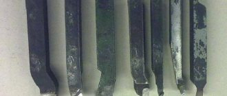
Also, processing of surfaces with a curved generatrix is carried out using shaped cutters. They correspond to the shape of the workpiece profile. There are the following types of these tools:
- Rod-type: they are easy to manufacture and are sharpened along the front surface. The disadvantage of these devices is complex sharpening, which can lead to distortion of the profile shape. For this reason, these tools are rarely used in production.
- Prismatic: have 2 protrusions for attaching to the slots of the machine. The upper plane acts as the front surface. This design allows you to maintain the location of the cutting edge during processing. The profile of these cutters is formed by grinding and milling.
- Spring cutters: equipped with a spring holder. They have a slot where a screw is inserted. This design allows you to control the rigidity of the holder. These cutters allow you to get the cleanest surface.
- Disc: have the shape of a disk with a front surface. Thanks to the presence of a cutout, they prevent the scattering of metal chips during processing. On the side parts of the cutting device there are triangular teeth that fix the location of the cutter.
Before turning the workpiece, the shaped cutter is installed on the center line of the machine. The cutting tool must be in a horizontal plane at an angle of 90° relative to the center line. It is important that the width of the cutter matches the diameter of the workpiece.
Sharpening is carried out along the front surface. The cutting edge must be positioned in the center of the surface to be machined. The feed must be uniform and consistent with the rigidity of the workpiece. The sharpening speed is 20% less than when grinding the outer surfaces of cylindrical products. During processing of a part, the cutter removes a large amount of metal chips, which leads to additional vibrations and vibrations. To stabilize the tool, it is necessary to reduce the cutting intensity and periodically cool the cutting edge using emulsion or oil.
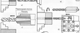
Processing shaped surfaces using a copier has many similarities with turning conical workpieces using a tapered ruler. A copier is a measuring instrument that has a curved outline. Using this technology, the cutter gives the workpiece a surface whose profile will be equivalent to the profile of the copier.
To process shaped surfaces using a copier, it is necessary to secure the roller in the rod and make longitudinal movements using a caliper disconnected from the transverse screw. As a result, the cutter receives not only longitudinal, but also transverse movement. During processing, the roller moves along a curved groove formed after applying 2 plates of a measuring tool with a curved outline. The cutter follows the movement of the roller and gives the shaped surface the final profile shape. If a one-sided copier is used for turning, the roller is pressed using a weight or a spring mechanism.
Nowadays, on an industrial scale, processing of shaped surfaces is carried out using specialized devices that impart a circular motion to the cutter along an arc with the appropriate radius. The most commonly used devices are hydrocopiers, which allow turning complex profiles and stepped rollers. Thanks to the use of this device, processing time is reduced and labor productivity at the enterprise is increased.
Using shaped cutters
It is advisable to produce parts of short length using cutters with a working edge that exactly matches the given contour. A prerequisite for accurate execution of technical cutting parameters is that the front surface of the cutting tool must be located at the level of the center line of the lathe. The front surface is used to sharpen cutters for shaping, which is important to consider if there is a need to install them repeatedly. You should check that the cutter is installed perpendicular to the center line of the machine - this condition significantly affects the quality and cleanliness of the cut. Perpendicularity is checked using a square, one edge of which is located in the direction of the axis of the part, the other along one of the sides of the cutter. The cross-section of the cutter body can be round or rectangular - this makes it easier to process surfaces with complex terrain.
The installation location for prismatic radial shaped cutters is a horizontal turret or a transverse support. The line of the cutting edge of the shaped cutter must be level with the center of the part fixed in the spindle or in the centers of the part. The dimensions of the clearance angles α can be set by adjusting the position of the cutter in the holder, which is quite convenient at the stage of preparatory work.
In metalworking industries, preference is, as a rule, given to cutters with helical generatrices of cutting edges compared to cutters in which the cutting edges are made in the form of ring generatrices. This is explained by the fact that the surface processed by cutters with a helical generatrix is less rough, while at the same time the cutting process occurs much faster.
The high performance of cutters with a helical cutting edge is fully exploited when they are installed in a turret. To improve cutting quality, a uniform feed of no more than 0.05 mm/rev is used with a cutter width of 10...20 mm. Wider shaped cutters (width greater than 20 mm) are designed for feed rates up to 0.03 mm/rev.
Subtleties of processing shaped surfaces
To ensure proper turning of shaped parts, it is important to install the cutting fixtures correctly. The working edge should be placed at level 1 with the centers of the machine. It is recommended to use a square to check the correct location of the cutting fixture. The first edge of the measuring tool is applied along the axis of the part. The second edge is brought to the side of the cutting tool. It is important to prevent the appearance of uneven lumen.
The amount of feed depends on the following factors:
- dimensional characteristics of the cutter;
- diameter of the workpiece;
- location of the part surface relative to the chuck.
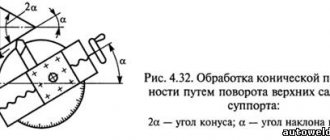
These parameters also apply when machining conical surfaces. With the correct proportion of the transverse and longitudinal feed values, it will be possible to give the product the most accurate shape that matches the template.
When processing a small number of products, it is not advisable to use shaped cutters, which are highly expensive and difficult to manufacture. If it is necessary to process a large batch of workpieces, then it is necessary to dampen the feed of the cutting device. This technique improves overall productivity.
During turning of workpieces with a curved generatrix, the following types of defects may occur: incorrect profile of the machined surface, low cleanliness of the turned product. These defects occur due to the following reasons:
- Incorrectly selected cutting tool shape.
- Setting the cutter at the wrong height.
- Poor quality sharpening of the turning device.
- Deformation of the product due to intense pressure from the cutting tool for a long time.
- Uneven movement of the cutting edge.
- Choosing the wrong location to place the copier.
- Large gap between the cutting tool and the copier.
To prevent defects from occurring, it is necessary to carefully install the cutters and workpiece on the lathe and check the condition of the working equipment and parts.
The main condition for processing parts on machines is compliance with safety precautions:
- A person working with turning equipment must have a special uniform: work coat, boots, hats and glasses. The overalls are designed to protect the technician from metal shavings and various types of injuries. The uniform must be buttoned. Hats and glasses must cover vital organs and be in good condition.
- Do not work with faulty equipment. It is important to check the serviceability of working devices to identify internal or external damage.
- Before carrying out turning work, it is necessary to check the machine chuck. It should not contain any particles or emulsions. It is also important to test run the machine and check the lubrication mechanisms, control and cooling systems.
- During turning, you need to monitor the position of the part and the cutting tool. Workpieces weighing more than 16 kg cannot be installed. When processing, it is important to monitor the removal of metal chips and drainage of the cooling liquid.
- It is prohibited to stop the chuck by hand, place foreign objects on the lathe, remove chips using a jet of air, or move away from the workplace.
- When working at high speeds, it is necessary to use steady rests and special chip removal devices.
During processing, unusual situations may arise:
- voltage appears on the metal parts;
- the phase has disappeared;
- there is smoke or vibration.
In this case, it is necessary to turn off the lathe, take people to a safe distance and report the breakdown.
Shaped cutters: types and their features
A shaped cutter is a metal-cutting tool in which the shape of the cutting edge follows the profile of the finished product. The simplest version of such a tool is a rod cutter. Depending on the design features, such cutters can be:
- designed for turning concave surfaces;
- prismatic;
- disk
The first type of shaped cutters is characterized by simplicity and inexpensive production. At the same time, their cutting blade is ground down after several sharpenings. This manifests itself in a decrease in the height of the cutter in the center during installation, making the tool unsuitable for further work. It follows from this that rod cutters of this type are used in single or mass production.
For prismatic cutters, the role of the front surface is played by the end of the block used to make the tool, and their rear angle is formed as a result of the inclination of the cutter when fixed in the holder. Their advantages include the possibility of strong fixation on the machine, but their disadvantages include the complexity of manufacturing.
Disc cutters are characterized by a simple design, which simplifies the process of their manufacture. Their main advantage is that they are not drawn into the workpiece during the turning process, therefore, the metal product is of high quality.
Control of shaped surface
Quality control of surface treatment is carried out using a template or a special protector by superimposing a profile of the processed part on an enlarged scale on the drawing. The choice of control method depends on the scale of production work, the required processing accuracy and the choice of design base. The following methods for controlling processing accuracy are distinguished:
- Universal coordinate. It involves numerical diagnostics of the location of individual zones of a shaped surface relative to the technological base. The calculation is carried out in rectangular and polar coordinate systems using measuring rods installed on the base points of the surface. The universal coordinate method refers to contact methods for controlling sharpening. The presence of errors during calculations depends on the shape of the rod tips.
- Sample comparison method. It consists in comparing the values of the profiles of the machined surface and the template workpiece. The nominal values of the reference parts are specified in the technological maps. During measurements, nominal and limit gauges with template profile values are used. They are applied to the surface of the product. This technology is used to control rough shaped surfaces with a large error (from 0.2 mm).
More accurate results of measuring the sharpening accuracy of parts can be obtained by using optical devices. In this case, the base points of the processed product are fixed by aiming the reticle of the optical sight at them.
Obtaining a shaped surface using two feeds operating in parallel
Turning of shaped surfaces by parallel action of feeds (longitudinal, transverse) is most often performed in cases where it is necessary to process a small number of parts or the surface being processed has a large area. If we consider this example, then the use of other processing options is simply illogical. For example, making even the simplest shaped cutter for a small batch is a bad idea, since the cost of such products will increase significantly, and processing a large surface would require a too wide tool, the operation of which would cause strong vibrations.
To remove the allowance using the above technique, you will need a finishing/through cutter.
In this case, the longitudinal slide of the caliper moves to the left, and along with this movement, the transverse slide moves forward/backward. Go to list of articles >>