Processing cylindrical surfaces on a lathe makes it possible to obtain various parts for mechanical engineering and other industries. The manufacture of rollers and bushings requires the use of longitudinal turning cutters and other special tools.
Sharpening of each part must be done using good equipment. With the help of a professional cutter you can achieve accuracy down to a hundredth of a millimeter. There are several options for metal processing:
- Draft
- Finishing
- Thin
In addition, the rigidity and strength of the future processed part may be different, based on this the amount of allowance is adjusted.
How is grinding done?
First of all, it is necessary to correctly set up the cutter for processing. To do this, initially make barely noticeable risks; they help to navigate during work. The first touch is almost imperceptible. Subsequently, the mechanical longitudinal transmission is turned on and the surface is processed, manually moving the caliper until it touches the metal. Initially, they try grinding at a distance of 3-5 mm; if everything turns out well, then they continue working to the required size.
The size is adjusted using a dial. This makes it possible to achieve maximum precision of the processed part. The limb ring allows you to immediately begin processing without trial notches and be confident in the correct dimensions. Along the length, either markings or limbs are also used. This can be measured automatically or using a ruler and caliper. Usually, a couple of centimeters before the desired size, the automation turns off and the process continues in manual mode.
Much in the processing process depends on the machine. Some of them have a limb with a diameter. The main thing is to make the calculations correctly and you can start working. The mathematical formula is very simple. Here it is necessary to take into account the initial diameter desired, as well as the cost of dividing the limbs. For example, these numbers could be 26, 22 and 0.05 respectively. The formula will be the difference in diameters divided by the division price. As a result, during processing it will be necessary to rotate the dial by 80.
Machining of cylindrical holes
Report on plumbing and mechanical practice Read more: And 40–60 m/min. For finishing passes, the cutting speed is increased by 1.5–2 times. For cutting internal threads, the cutting speed is reduced by 20-30%
2.4 Machining of cylindrical holes.
Cylindrical holes serve as working cavities for engines, pumps, compressors, and are used for supplying lubricant or coolant. The shape of cylindrical holes can be smooth, stepped or with a groove; holes can also be through or blind.
Pre-drilled holes or holes in cast or forged workpieces are often bored to increase the diameter, provide high dimensional accuracy and low roughness.
Boring is less productive than drilling, but it allows you to obtain precise holes with a diametric tolerance of up to 0.02 mm, and correct the position of the hole axis. This method is the most universal way to process holes on a lathe.
Boring cutters. They are: through holes for through holes and persistent for blind holes. Boring cutters equipped with a carbide snail crown are also used. The boring cutter is fixed in the tool holder parallel to the axis of the workpiece. For standard cutters, the cutting edge is located at the level of the upper generatrix of the cylindrical holder and therefore the cutter is installed below the center of the workpiece
And.
Boring bars (boring bars). Holes Ø80-100 mm and more are usually bored using boring cutters, which are fixed in mandrels. The cutter in the mandrel is clamped with a screw from the end or from the outer surface of the mandrel. The mandrel can hold both cutters and inserts. A groove is milled on the mandrel through which the coolant falls directly onto the cutter. The groove also serves for locking with bolts.
Measuring boring plates (“knives”). The boring plate (knife) has a size corresponding to the size of the hole being bored. Boring with a plate ensures that a hole of the correct shape is obtained in one pass, since the forces acting on the plate from both sides are mutually balanced.
Boring techniques. The specified hole depth is ensured during the boring process by measuring with a ruler, depth gauge, template or setting using a longitudinal feed dial. To facilitate processing, a mark is applied to the cutter corresponding to the specified hole depth. The accuracy of the diameter of the hole being bored is ensured in the same way as with external turning: trial passes with measurements with a caliper, adjustments using the cross-feed dial, along the line of the cross slide of the caliper, using an indicator, and using the cross-stop.
The internal ends and ledges are trimmed with a boring stop cutter, feeding towards the center; for this, the boring cutter must have a leading angle j of more than 90°.
Wide internal grooves are processed by sequential cutting to the depth of the groove using a transverse feed and expanding the groove using a longitudinal feed. The width of the groove in the hole is controlled with a caliper and a template. The diameter of the grooves is measured with a caliper with special jaws. The size read on the caliper is added to
double width of legs (2h).
2.5 Machining of conical holes.
Conical holes are bored when feeding the cutter with the rotated upper slide of the caliper, as well as using a conical ruler. A hole is pre-drilled, the diameter of which is less than the small diameter of the cone. To facilitate boring, the hole is prepared by stepwise drilling.
Standard shallow-angle conical holes (such as Morse taper) can be machined with a set of conical countersinks and reamers. After drilling, the holes are processed with two stepped countersinks, then finally with a conical reamer with smooth teeth. To process standard instrumental internal cones, a special tool is used - a two-flute conical countersink. Short internal cones are processed with a cutter or countersink. Conical holes for standard pins are drilled with special conical drills.
In serial and mass production, conical holes are controlled by limiting conical gauges: plugs and bushings. the distance between the marks or the size of the shoulder at the end of the gauge corresponds to the taper tolerance. If one mark on the plug goes into the controlled hole, but the second does not, then the cone is correct. Similarly for a bushing gauge with a shoulder: if the end of the controlled cone is within the marks on the shoulder, then the cone is correct. More precise control of cones using special instruments is carried out in measuring laboratories.
2.6 Thread cutting.
Thread cutting is an operation performed by chipping or rolling, as a result of which helical grooves are formed on cylindrical and conical surfaces.
Thread cutting with dies. Dies are used to cut the outer surface of a triangular profile fastening thread in increments of up to 2 mm. Sometimes dies are used to calibrate coarse pitch threads that have been previously cut with a cutter. The die is similar to a nut, made of tool steel and having the same threads that it is intended to cut. The threading die is mounted in a manual die holder or in a self-aligning die holder, which is inserted into the tailstock quill.
When cutting a thread with a die fixed in a manual die holder, it is brought to the workpiece, supporting the die holder with the end of the tailstock quill; the handle of the die holder rests against the caliper. After cutting two or three turns with pressure, further feeding of the die occurs by self-screwing.
The rod for threading with a die is ground to a diameter smaller than the diameter of the thread being cut, to compensate for some metal extrusion.
Before threading begins, a chamfer is machined at the end of the workpiece to facilitate insertion of the die. Thread cutting with dies is performed at a cutting speed of 2 m/min for steel and cast iron and up to 10 m/min for non-ferrous metals. Emulsion and mineral oil are used as a lubricant for steel, and kerosene for cast iron.
Self-expanding thread-cutting heads operate on the same principle as dies. The cutting speed when cutting threads with threading heads is 15-20 m/min. Threading heads have high durability.
Thread cutting with cutters.
Preparing the workpiece for cutting. When turning a workpiece for subsequent threading, take into account that during cutting some metal is squeezed out of the cavities. Therefore, the diameter of the shaft for the thread should be slightly smaller than the outer diameter of the thread, and the diameter of the hole should be larger than the inner one.
The diameters of the shaft and holes when preparing the surface for threading are determined from reference books. At the end of the threaded section, a groove (groove) is machined for the entry of the cutter. The width of the groove must be no less than the thread pitch. The depth of the groove should be 0.1-0.2 mm greater than the depth of the thread.
Installation of the cutter. The thread cutter is installed exactly in the center of the workpiece: installation below the center leads to distortion of the profile, and installation above the cutter. To obtain the correct thread profile, the cutter is installed according to the template.
The template is applied to the workpiece at the level of its axis, and the cutter is inserted into the profile cut. The correct position of the cutting edges of the cutter is checked for “clearance”, and then the cutter is secured and the template is removed.
Thread cutting. The thread is cut in several working strokes; After each working stroke, the cutter is removed from the groove, the caliper is returned to its original position and the working stroke begins again. The number of working strokes and the plunge depth for each working stroke depend on the pitch of the thread being cut and the material of the thread cutter.
When cutting long threads it is advisable
o return the caliper to its original position manually or automatically with the split nut open. However, in this case it becomes necessary to ensure that the thread cutter enters the thread after each
working stroke.
Side entry. Threads with large pitches (2 mm or more) are cut not with a transverse, but with a lateral plunge of the cutter, in which only one cutting edge works. With lateral cutting, the cutting process is facilitated and quality is improved.
To carry out lateral cutting, the upper slide of the caliper is rotated at an angle (for metric threads = 30°) relative to its normal position. Plunging is carried out using the handle of the upper slide of the caliper. The last one or two finishing strokes are performed with transverse feed. At the moment of cutting into the thread, the cutter is pressed out somewhat under the action of an axial force, and the first turn of the thread is more complete than the rest. The last turn is also more complete.
Left-hand thread cutting is carried out by rotating the lead screw in the direction opposite to the rotation of the spindle. To do this, switch the mechanism for reversing the rotation of the lead screw - the transel. When cutting left-handed threads, the plunge is made into the threaded groove, and the support with the cutter moves from left to right.
Cutting modes when cutting threads with a cutter. The cutting depth is determined by the number of passes. The feed when cutting a thread is equal to the thread pitch, and when cutting a multi-start thread, it is equal to the stroke (H = KS, where K is the number of starts).
The cutting speed depends on the material of the threaded cutter being processed: when processing steel with high-speed cutters it is 20–35 m/min, when processing cast iron 10–15 m/min, when processing with carbide cutters – respectively 100–15
Report on plumbing and mechanical practice Read more: And 40–60 m/min. For finishing passes, the cutting speed is increased by 1.5–2 times. For cutting internal threads, the cutting speed is reduced by 20-30%
Information about the work “Report on plumbing and mechanical practice”
Section: Technology Number of characters with spaces: 42457 Number of tables: 0 Number of images: 23
Similar works
Report on the first technological practice at the Luch Pilot Plant
22875
0
25
... structures in electronics products, radio communications, for protective and decorative coatings and tinting of consumer goods. Used in magnetron cathode sputtering installations. Description of the technological process by operation. 1. Sorting of scales is carried out on a work table covered with plastic film, by pouring and manual selection using shovels, scoops, ...
Gas turbine unit type GTT-3. Report on practice at NAC "AZOT"
47900
4
0
... the supercharger consists of a hydraulic cylinder, a movable cam clutch with a spring mechanism placed on the worm wheel shaft. 4. PURPOSE OF THE SPECIFIED EQUIPMENT IN THE TECHNOLOGICAL PROCESS The gas turbine unit type GTT-3 is intended for air supply to the workshop for the production of weak nitric acid with the simultaneous generation of a certain amount of electricity and heat use...
Design, testing and adjustment of the brake system of the VAZ-2108 car (report)
27609
0
7
… . Taking into account the expected amount of work and the workload of the enterprise, a decision is made on the specific time for accepting the machine for repair or maintenance. 3. Design, check and adjustment of the brake system of the VAZ-2108 car 3.1 Design of the brake system The car uses a service brake system with diagonal separation of circuits, which significantly ...
Financial methods of cost management in an enterprise
131978
16
10
... participants: open (closed), mutual (two-way) and full service. At the end of the theoretical review, we can conclude that the essence of financial methods of cost management in an enterprise has been determined. Various methods of analyzing the financial condition were also considered and characteristics of the methods of financial stability of the enterprise were given. To implement effective...
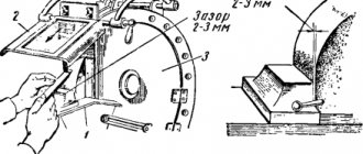
Features of using limba
It is very important to achieve maximum accuracy when processing a specific part. A limba is used specifically for this purpose. A serious error can occur in a situation where the clearance in the caliper movements is not taken into account. During manual movement of the caliper during one small movement of the flywheel, the device itself will not move.
This is what the backlash and its size mean. In order to neutralize the possibility of error when processing by size, it is imperative to slowly and carefully rotate the flywheel in one direction. When moving back, there will be some play. Each technique has a specific one. If an error was made during processing and the caliper moved a greater distance, then it is better to go back and then again try to ensure that the surface is processed accurately.
Such processing of external cylindrical surfaces is a precise turning of parts, which allows you to create a part of a certain size and shape. The essence of turning work is cutting metals, which includes cutting with internal and external rotation. Specifically, turning means working directly on external surfaces.
Many serial parts are manufactured using a similar method, using the same specific settings. There is also individual work, when you need to do some grinding of an external element to order and give the metal an unusual shape. Rough metal is usually used as blanks, which later takes on an ideal shape.
Grinding stepped surfaces
Processing of external cylindrical surfaces must be carried out by professionals. Only they know exactly how to deal with these problems, in particular, how exactly to use a certain technique. To do this, you need to approach each task individually.
Grinding stepped surfaces poses some difficulty if the height of the ledges is not too high. With a larger diameter this usually does not cause problems; you can press it hard enough to achieve maximum precision when processing.
A solution to the problem can be the use of steady rests when processing external elements. This is competent, precise support for the part. She guarantees that the size will be respected. During rotation, the position of even the smallest metal outer surface of the workpiece does not change and the machine can accurately cut metal.
Separately, it is worth considering the need to increase productivity. The use of lunettes allows processing to be done in different ways. If we are talking about a rough part, then most often the cuts are simply deepened. When it is finishing and accuracy is important, the speed of the cutter increases. Modern devices are capable of independently calculating dimensions for a specific surface treatment.
For steps, several cutters are often used, which can work alternately. This helps cope with higher speeds while still providing the fastest possible surface finish.
It can be trimmed, grooved, shaped, depending on the purpose; persistent ones are also popular specifically for creating ledges on the surface at right angles. During operation, such a system will be more expensive, but the high level of productivity justifies the costs during active production. Regarding special thrust cutters, they can be used for roughing and finishing.
The design of the multi-cutter machine is used for processing and turning all cylindrical parts of the part. The process is carried out using one, or less often several, cutters, and it is for this reason that machines require a “multi-stroke” front support. Due to the support, the performance of the cutters varies.
Plunging for processing the surface of a part is called “oblique”, as it is ensured by deep penetration of the cutter to the depth of the allowance at the same time as its longitudinal feed.
Types of machine cutters:
- scoring cutter;
- former;
- groove (depth) cutter;
- persistent cutter, etc.
Turners most often use persistent cutters, which have a section angle of 90 degrees. Thrust cutters make it easy to cut ledges on the surface of a part; cutters of this type should also be used for turning shafts. Cutters are used more often than others due to the minute transverse deflection of the workpiece.
In order to choose from all the cutters the one that is suitable for processing a given part, you should pay attention to the durability of the cutter. Through cutters are suitable for any turning work. Moreover, they will be used for roughing and finishing surface treatment and turning parts.
To carry out rough work, the cutter is sharpened and rounded. R rounding should be between 0.5 mm and 1 mm. For finishing, the radius of curvature is made from 1.5 mm to 2 mm. If the radius is increased further, the roughness of the treated area will decrease.
Drilling
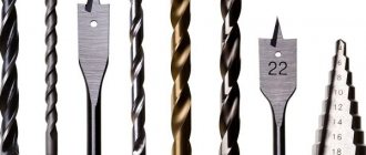
To process holes, they must first be obtained, for which various technologies can be used. The most common of these technologies is drilling, performed using a cutting tool called a drill.
Main parts of a twist drill
Using drills installed in special devices or equipment, both through and blind holes can be produced in solid material. Depending on the devices and equipment used, drilling can be:
- manual, performed using mechanical drilling devices or electric and pneumatic drills;
- machine tools, carried out using specialized drilling equipment.
The physics of drilling holes
The use of manual drilling devices is advisable in cases where holes, the diameter of which does not exceed 12 mm, need to be obtained in workpieces made of materials of small and medium hardness. Such materials include, in particular:
- structural steels;
- non-ferrous metals and alloys;
- alloys made of polymer materials.
If it is necessary to make a hole of a larger diameter in the workpiece, and also to achieve high productivity of this process, it is best to use special drilling machines, which can be desktop or stationary. The latter, in turn, are divided into vertical and radial drilling.
Reaming, a type of drilling operation, is performed in order to increase the diameter of a hole previously made in a workpiece. Drilling is also performed using drills whose diameter corresponds to the required characteristics of the finished hole.
The physics of drilling holes
This method of processing holes is undesirable for those that were created by casting or through plastic deformation of the material. This is due to the fact that sections of their inner surface are characterized by different hardness, which causes uneven distribution of loads on the drill axis and, accordingly, leads to its displacement. The formation of a layer of scale on the inner surface of a hole created by casting, as well as the concentration of internal stresses in the structure of a part made by forging or stamping, can cause the drill not only to move from the required trajectory when drilling such workpieces, but also to break.
When performing drilling and reaming, it is possible to obtain surfaces whose roughness will reach Rz 80, while the accuracy of the parameters of the hole being formed will correspond to the tenth grade.
The process of installing cutters on the machine
For lathes to work correctly, it is important to secure the cutters very firmly. Fastening occurs in the caliper rest holder. It is important to determine the position of the cutter by relating it to the center of the machine axis.
If work is supposed to be done using external sections of cutters, then the installation is carried out so that the top of the cutter is correspondingly at the level of the centers of the machine. If turning shafts or roughing surfaces is required, the tip of the cutter should be 0.02 mm from the center.
The installation height is controlled using steel pads. 2 pads are used. The dimensions of the backing should be standard to ensure a strong position of the cutter over the entire surface of the support. Control after the linings is ensured by aligning the tip of the cutter with any of the centers of the machine, or the cutting end of the workpiece being processed.
It is also important to position the cutter so that it is perpendicular to the axis of the centers and has a minimum protrusion from the holder (protrusion no more than 1.5 mm from the height of the rod itself). Fastening occurs using paired screws. Adjustment is carried out at the lowest level, in the case of the surface grinding process. And if there is no step, then adjustment is made as the cut wears out and ledges form.
Experts know that the speed of the wheel during grinding of the elements being processed is, as a rule, limited by the strength of the wheel itself. Basically, when turning, the speed is limited and can be no more than 35 m/second. If the surface grinding speed reaches at least 75 m/second, then high-speed wheels are already used.
Countersinking
Countersinking is used for preliminary and final processing of holes after casting, stamping, rough drilling, and for aligning the ends of workpieces. Before using countersinks, holes in parts produced by casting, forging, and stamping are subject to boring with a cutter to the size of the countersink. The processing depth can reach 50% of the length of the working part of the countersink. On a lathe, a countersink can be installed in the tailstock quill, in a special device on the machine support, or in the turret.
How does rotation speed affect surface finish?
It is no secret that the speed of rotation of the material being processed, taking into account various equal conditions, determines the specific amount of metal that can be removed in a certain time period. If the rotation speed is too high, this can lead to rapid clogging of the wheel and thus it may simply become impossible to process the workpiece by grinding. Therefore, it is necessary to select the optimal rotation speed, which can range from 16 to 60 m/minute. It is necessary to select the speed after determining the cutting depth and the feed itself.
Grinding methods
At the moment, there are two methods of cylindrical grinding during turning operations. This is, first of all, a method when the part is ground with the so-called longitudinal approach or feed, as well as a similar operation with a transverse plan feed, that is, with plunge-in.
The first option is made with a small cutting depth. This leads to the fact that a very small percentage must be withdrawn many times. The shallow depth makes it possible to apply significant feeds per certain revolution of the cylindrical workpieces themselves.
The second option requires a wheel width several times larger than, say, the actual length of the grinding surfaces. Thanks to such parameters, that is, a significant width or grinding area, a small feed per revolution of the part is possible S0 = 0.001-0.005 mm. It should be noted that in this case, the calculated processing of the outer cylindrical surfaces is equal to the value of the allowance per side. Thus, this method is the most productive in comparison with the first processing method, when the workpiece being processed is subjected to numerous influences.
Various nuances of grinding
The flat parts of the cylinder are ground using the side area. To reduce the contact area and process most of the external surfaces, use a tool with a conical lateral surface.
When using centerless grinding units, two main processing methods are used. First of all, this is a through-feed option.
This method is used to grind the outer surfaces of parts that do not have ledges. The processing procedure in this option is carried out continuously, and the workpieces themselves are laid from one part, and ready-made ones are accepted from the other. In this case, the number of passes can vary from two to six and depends on the allowance to obtain a certain accuracy when processing a cylindrical part.
Another plunge method is used when processing cylindrical workpieces with so-called shoulders. With this method, the axis of the circle is set in a parallel position to the axis of the cutting tool with an angle of up to 0.5°. In this embodiment, movement of the axis is not allowed, using a stop for this.
For large series, that is, for mass production in production, in order to increase quantity and productivity, the method of combined processing or grinding of cylindrical parts is used. In this case, the combination of the transitions themselves can be achieved using a wide tool, that is, a circle or a whole set of several different circles.
You can order turning production of all types of parts with a cylindrical surface.
Deployment
The reaming method refers to finishing methods for processing materials by cutting and allows you to obtain high cleanliness and accuracy of holes. Reamers are installed in oscillating mandrels on lathes and turret lathes. This type of mandrel allows you to adjust the position of the tool if its axis does not coincide with the axis of the hole. The machining of holes on a lathe can be performed with particular precision if successive operations of drilling, countersinking, and boring are performed without reinstalling the part in the machine chuck. When performing countersinking and boring, it is allowed to use the same reference materials as when drilling. But, taking into account the insufficient rigidity of fastening the tools of the core group on lathes, the cutting operating conditions are often changed downwards.