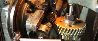
A worm pair is a mechanical connection consisting of a screw thread (worm) and a gear. They are widely used in industry, in gearboxes, control systems and control units. Because both components of the worm gear require a high degree of precision and are manufactured to closely match each other, when the connection fails, it is usually replaced entirely. When creating them, it is also important to consider the type of connection and the required physical characteristics. The Metallocentre production enterprise invites you to order the production of worm pairs according to your drawings. We provide affordable prices, high quality and prompt delivery throughout Moscow, the Moscow region, as well as to other regions of Russia.
Types of worms
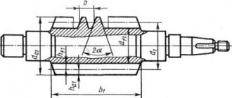
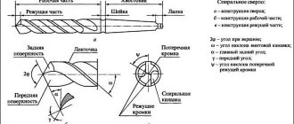
The screw thread in the transmission can have different dimensions, differ in material and shape. It is important to take these features into account when manufacturing worm gear pairs. According to the profile, the screw thread can be
- Archimedean;
- involute;
- globoid;
- non-currency.
Worms are also divided into multi- and single-thrust, left and right. Various materials are used to make screw threads, but most often these parts are composite. When creating a crown, it is important to take into account that it must have anti-friction properties. One of the most common materials for its creation is bronze. In order to reduce the cost of a part, its core is usually made from a durable and cheaper alloy, such as tool steel. This technology does not degrade the physical properties of the product.
Production of worm pairs here
We have been manufacturing worms and worm wheels to order in St. Petersburg for almost a quarter of a century. And with us, of course, you can produce not only worm wheels and worms, but also the production of other types of gears:
- spur gears;
- cylindrical helical gears;
- cylindrical gears with an internal crown;
- spur bevel gears;
- gears with a circular tooth;
- gear racks,
as well as sprockets and spline connections, manufactured according to the Customer’s drawings or samples.
You can get acquainted with our capabilities for the production of gears, sprockets and spline cutting here.
Find out about our other opportunities in the field of custom metalworking services on the main page of our website.
Production of worm pairs
Each element is manufactured using its own technology:
- The production of worms is carried out on various types of machines: lathes, milling and gear hobbing. In addition, there are special devices equipped with a cutter. Production with their help provides the highest levels of accuracy, but requires the highest costs.
- To produce wheels in worm pairs, gear hobbing machines are used. During production, both radial and tangential feed of the working tool can be used.
To produce worm gear pairs, you need equipment that can provide the required level of accuracy. Our company uses computer numerical control (CNC) machines, which guarantee minimal error and quality control at every stage.
Manufacturing of worm wheels
Worm wheels are made from a cast iron hub and a bronze crown and are assembled with bolts or a press fit followed by locking.
Blanks for worm wheel hubs are cast in sand or metal molds. The crown blank is usually obtained by centrifugal casting. First, the hub and crown are processed separately along the mating surfaces. The hub is processed on a turret or lathe in two settings. The crown is bored on a lathe or rotary lathe. The hub and crown, mating in an interference fit, are assembled (after heating the crown) on a press using a mandrel.
Processing in assembled form includes two turning or turning-carousel operations and pulling the keyway in the hole. When turning a wheel rim, a groove of small radius is processed with a shaped cutter. With a radius of less than 35-40 mm, a shaped cutter is made to cover the entire profile; with a larger radius, preliminary turning is carried out with two cutters (for the left and right parts of the groove) and finishing - with one cutter for the entire profile. Undercuts of a larger radius are processed with a through cutter when feeding a circle of a given radius, communicated to the cutter using a device with a worm gear.
In a universal device (galtelyum) for processing a surface along a circular arc with manual rotation of the worm, the worm wheel is rotated, and with it the tool holder with the cutter; pre cutter
They are installed in the required position relative to the workpiece and the axis of rotation of the worm wheel so that its top moves along a circular arc of a given radius.
When the handwheel mounted on the shank of the screed rotates, the worm wheel and the bevel wheel sitting on the same axis with it are rotated; the second conical wheel engaged with it rotates the cutter; The cutter overhang is pre-adjusted using a template. In this operation, in addition to the specified radius and diameter along the bottom of the groove, a symmetrical arrangement of the ends of the workpiece relative to the middle plane c - c of the wheel is ensured (equal dimensions a to both ends). To do this, when cutting the ends of the wheel, a turning template 3 and a feeler gauge of a given thickness are used to check the equality of the gaps s on both sides.
This property of the workpiece allows, during assembly, to use the end surfaces as measuring bases to ensure the accuracy of the location of the worm axis in the middle plane of the wheel in the assembled gear. Machining of the workpieces after assembly, including the radius groove on the rim, can be done on a computer-controlled lathe, similar to the machining of a gear coupling bushing with a spherical rim shape.
See also:
- Catalog of cranes.
- Beam cranes: production catalogue.
- Overhead cranes: production catalogue.
- Gantry cranes cranes: production catalogue.
- Console cranes: production catalogue.
- Catalog of electrification systems.
- official representative office of the crane plant in Ufa.
Operating procedure
1. We accept the application
You send an order in any convenient way, and also provide drawings or examples of products. Our managers will contact you to clarify the details of the work.
2. We make parts
We fulfill the order within the specified time frame and in the specified volume.
3. We carry out checks
We check the finished batch for defects.
4. Delivery to site
We send you finished products by the nearest available transport.
Prices for services
| Name | Price |
| Gear manufacturing | Calculate the cost |
| Manufacturing of gear shaft | Calculate the cost |
| Making stars | Calculate the cost |
| Manufacturing of worm wheels | Calculate the cost |
Worm pairs: worm wheels and worms
The worm pair transmits rotation along intersecting (but not intersecting, unlike bevel gears) axes.
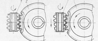
The worm pair consists of a worm wheel and a worm. The worm wheel is made of antifriction material (cast iron, bronze). Often the middle part of the worm wheel is made of steel, and a crown made of bronze (sometimes cast iron) is put on it. The worm is a screw with a special “thread”. Worms are made not only single-start, but also multi-start (as, for example, in the pictures above).
The production of worm wheels and the production of worms is a very popular operation due to the widespread use of worm gearboxes, which is due to a number of advantages of worm pairs:
- large gear ratios in one pair and, as a consequence, compactness of gearboxes;
- often, ease of arrangement due to the crossing of the shaft axes;
- smooth and quiet operation;
- at a small lifting angle of the worm, they have a self-braking effect, being irreversible (you cannot rotate the worm by applying force to the worm wheel).
Disadvantages of worm pairs:
- increased friction losses and, as a result: high requirements for assembly quality; low efficiency;
- heat generation;
- high wear;
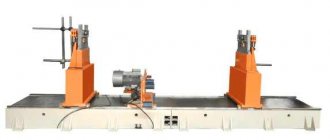
Necessary equipment
Equipment parameters
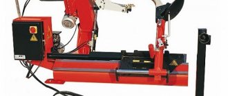
The selection of the necessary equipment is carried out according to the production tasks, the specified power parameters and productivity of the gear shaving machine. The main motor drive of a semi-automatic machine can be hydraulic or electromechanical.
Industrial plant equipment is characterized by the following parameters:
Gear shaving machine - characteristics
- The speed of the workpiece turning cycle, the productivity of the machine in a given unit of time.
- The maximum diameter of the part to be processed, range of values is 125–4000 mm.
- Main drive power of the engine, power consumption varies between 1.0–14 kW.
- Gear module. The size of the gear module is determined by the thickness of the tooth wall.
- The method of feeding the working tool relative to the axis of the part undergoing rework.
For example, the widespread industrial machine model 5702 is designed for grinding wheel teeth with a diameter of up to 200 mm, with a module of up to 6 mm.
The flywheel rotation speed is adjustable in the range from 78 to 395 rpm, the power of the main drive of the machine is 2.8 kW.
Gear shearing machine model 5702
Shaver Shape Classification
In the operation of shaving gears on machine tools, the following cutting tool is used:
- a toothed rack with notches, the tool is called a rack;
- a toothed disk with cutting edges, or a disk shaver;
- tight-fitting shaver, used mainly for shaving barrel-shaped teeth;
- worm gear.
Cylindrical workpieces are turned with rack and disk tools; the worm type of cutter is used for shaving the metal of worm gears.
Types of tool feed
The machine engine imparts working movement to the cutter, which, after engagement, transmits the movement of the workpiece. The working stroke of the shaver, the speed and number of turning passes depend on the type of feed.
Types of cutting tool feed:
Determination of the main time for gear shaving operations
- cross feed - the cutting edges move perpendicular to the axis of the workpiece;
- longitudinal feed of the cutter - coincides with the direction of the axis of the part;
- tangential feed - the workpiece is located perpendicular to the axis of the shaver;
- diagonal tool feed - at an angle to the axis of the workpiece.
When using longitudinal feed, the pitch of the shaver stroke coincides with the size of the teeth of the workpiece being processed. The same cutting edges are involved in the operation, which leads to uneven wear of the cutter and increases the cost of equipment repair.
Transverse direction, tangential and diagonal feeds increase the life of the cutter, ensure uniform wear, and shorten the stroke. Processing cycle time is reduced, equipment productivity and the overall economic effect are increased. The tool produces the minimum stroke of movement with tangential feed.