To search for treasure in the ruins of a castle, fasteners in building structures and solve other practical problems, you can make a metal detector with metal discrimination with your own hands. This publication discusses the advantages and disadvantages of different designs. Practical recommendations will help you correctly assemble and configure a functional measuring device.
Making a simple metal detector is easy even for a novice radio amateur.
How the device works
To get a working unit, you need to understand the basics of electromagnetic induction. This is how the first coil of the device creates a signal that penetrates the soil. The second, receiving one, processes impulses transmitted by artifacts located in the ground. Often, for convenience, two coils are combined into one unit - a transmitting and receiving coil. The adjustment circuit allows you to create a sound of a certain tonality, which indicates that an object with a metal structure has entered the search area. An addition is an LCD panel that allows for visual indication.
In terms of design, the device includes:
- Transceiver coil;
- Device for generating electromagnetic radiation;
- Receiver;
- Decoder;
- A rod that acts as a support for all elements of the detector;
- Indicator.
For convenience, the listed elements are located on a bar, the length of which is selected based on the user’s physique. The determinant is built into the control unit. The task of the discriminator is to accurately determine the type of artifact through disturbances in the electromagnetic field.
One of the simple metal detectors with the Megatron discriminator
Here are brief characteristics of the device
According to the principle of operation, the metal detector is also pulse-balanced. The operating frequency is 8-15 kHz.
As for the discrimination mode, it uses two-tone voice acting. When iron is detected, the device emits a low tone, and if non-ferrous metal is detected, the tone will be high.
The device is powered from a 9-12V source.
There is also the ability to adjust sensitivity and there is manual ground adjustment.
Well, now about the main thing, about the detection depth of the metal detector. The device is capable of detecting coins with a diameter of 25 mm at a distance of 35 cm in the air. A golden ring can be caught at a distance of 30 cm. The device detects a helmet at a distance of about 1 meter. The maximum detection depth is 150 cm. As for consumption, without sound it is about 35 mA.
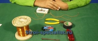
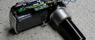
Materials and tools for assembly: – mini drill (the author has a homemade one from a motor); – wire for winding the coil; – four-core shielded cable; – soldering iron with solder; – materials for making the case; – printed circuit board; – all necessary radio components and their ratings You can see the diagram in the photo.
Metal detector manufacturing process:
Step one. Board manufacturing
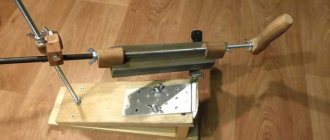
The board is made by etching. Next, you can drill holes, their diameter is 0.8 mm. For these purposes, the author uses a small motor with a drill installed.
Step two. Assembling the boardAssembly must begin with soldering the jumpers. After this, you can install panels for microcircuits and solder other elements
For quality assembly, it is very important to have a tester that can measure the capacitance of capacitors. Since the device uses two identical amplification channels, the gain along them should be as close as possible to the same value, that is, be the same
Both channels of the same cascade must have the same readings when measured by the tester.
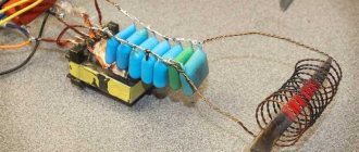
You can see what the already assembled circuit looks like in the photo. The author did not install a unit that determines the degree of battery discharge.
After assembly, the board must be checked with a tester. You need to connect power to it and check all strategically important inputs and outputs. Everywhere the power supply must be exactly the same as in the diagram.
Step three. Assembling the coil
The DD sensor is assembled according to the same principle as for all similar balancers. The transmitting coil is designated by the letters TX, and the receiving coil by RX. In total, you need to make 30 turns of wire folded in half. The wire used is enameled, with a diameter of 0.4 mm. Both the receiving and transmitting coils are formed by double wires, resulting in four wires at the output. Next, the tester needs to determine the arms of the windings and connect the beginning of one arm to the end of the other, as a result, the middle terminal of the coil is formed.
To fix the coil after winding, you need to wrap it well with thread and then soak it with varnish. After the varnish has dried, the coils are wrapped with electrical tape.
Subsequently, a screen of foil is made on top; between the beginning and the end you need to make a gap of about 1 mm to avoid a short-circuited turn.
The middle TX pin must be connected to the board ground, otherwise the generator will not start. As for the average RX output, it is needed for frequency adjustment. After adjusting the resonance, it needs to be insulated and the receiving coil turns into a regular one, that is, without a lead. As for the receiving coil, it is connected instead of the transmitting coil and set to 100-150 Hz lower than the transmitting coil. Each coil must be configured separately; when tuning, there should be no metal objects near the coil.
To balance, the coils are shifted, as can be seen in the photo. The balance should be within 20-30 mV, but not more than 100 mV.
The operating frequencies of the device range from 7 kHz to 20 kHz. The lower the frequency, the deeper the device will go, but at low frequencies the discrimination becomes worse. Conversely, the higher the frequency, the better the discrimination, but the smaller the detection depth. The golden mean can be considered a frequency of 10-14 kHz.
To connect the coil, a four-core shielded wire is used. the screen is connected to the body, two wires go to the transmitting coil and two to the receiving coil.
Well, in conclusion, all that remains is to configure the device. When the discriminator knob is set to minimum, the device should see all non-ferrous metals. Next, when screwing on the discriminator, all metals should be cut out in order up to copper, but copper should not be cut out. If the device works exactly as described, then it is assembled correctly.
We advise you to study Surge protection in a private home
The stability and sensitivity of the metal detector are ensured by the following circuit solutions:
The reference and measuring generators are separated - made in separate microcircuit packages - DD1 and DD2. At first glance, this is wasteful - only one logical element of the microcircuit package is used out of four. That is, yes, the reference generator is assembled on only one logical element of the microcircuit. The remaining three logical elements of the microcircuit are not used at all. The measuring generator is built in exactly the same way. It would seem that it makes no sense not to use the free logical elements of the microcircuit package. However, this is precisely what makes a lot of sense. And it consists in the fact that if, for example, you assemble two generators in one microcircuit package, they will synchronize each other at close frequencies. It will not be possible to obtain the slightest changes in the resulting frequency. In practice, this will look like a sharp change in frequency only when a massive metal object is close to the measuring coil. In other words, sensitivity sharply decreases. The metal detector does not respond to small objects. The resulting frequency seems to “stick” to zero—up to a certain point, there are no beats at all. They also say “ dull metal detector ”, “dull sensitivity”. By the way, “ Metal detector on a microcircuit ” - Radio magazine, 1987, No. 01, pp. 4, 49 is built on just one microcircuit at all. This effect of frequency synchronization is very noticeable there. It is completely impossible for him to search for coins and small objects.
Also, both generators must be shielded with separate small screens made of tin. This increases the stability and sensitivity of the metal detector as a whole . It is enough to simply solder small partitions made of tin at minus between the generator chips to ensure that the parameters of the metal detector are improved. The better the screen, the better the sensitivity (the influence of the generators on each other is weakened and plus protection from external influences on the frequency).
Electronic tuning.
All classic BFO circuits (BFO circuits of the last century) use a variable capacitor KPI to adjust zero beats This lousy element initially negates all the capabilities of a beat-based metal detector . Never use KPIs in BFO ! Even if it does not have backlash, it will still be a source of parasitic frequency changes due to temperature and capacitive influences of the environment. Searching in real field conditions with a condenser metal detector on beats is pure torture.
Read also: Diode d18 precious metal content
Electronic tuning only! It is implemented using zener diode D1, included in the circuit as a varicap. This scheme provides good frequency tuning in the absence of parasitic phenomena. Instead of KS147, you can use, for example, KS133, KS156 and many others. Also, many diodes have varicap properties. Naturally, you may have to select resistors R1, R3. Perhaps R3 will need to be short-circuited altogether with another zener diode or diode.
Comparator on DD3.2 – DD3.4.
This circuit element converts the sinusoidal signal from the output of the DD3.1 mixer into rectangular pulses of double frequency.
Firstly, rectangular pulses are clearly audible at hertz frequencies as clear clicks. While a sinusoidal signal of hertz frequencies is already difficult to distinguish by ear.
Secondly, doubling the frequency allows the adjustment to come closer to zero beats. As a result, by adjusting you can achieve a “clicking” sound in the headphones, the change in frequency of which can already be detected when you bring a small coin to the coil at a distance of 30 cm.
Generator power stabilizer.
Naturally, in this circuit, the supply voltage noticeably affects the frequency of the generators DD1.1 and DD2.1 of the metal detector . Moreover, each of the generators is affected differently. As a result, as the battery discharges, the beat frequency of the metal detector also “floats” . To prevent this, a five-volt stabilizer DA1 was introduced into the circuit to power generators DD1.1 and DD2.1. As a result, the frequency stopped “floating”. However, it should be said that, on the other hand, due to the five-volt power supply of the generators, as a whole decreased Therefore, this option should be considered optional and, if desired, generators DD1.1 and DD2.1 can be powered from the crown without a DA1 stabilizer. You just have to adjust the frequency manually more often using a regulator.
Technical characteristics of the Sokha 3TD-M metal detector:
- Operating frequency – from 5 to 17 kHz (Depends on the sensor);
- Ground balance – manual;
- Metal detector power supply – 12 volts;
- Current consumption (Without backlight and in the absence of metal) – 25 mA;
The metal detector has the following controls:
- 2 Sens buttons – sensitivity adjustment + screen backlight + filters.
- Volume control knob.
- Ground balance knob.
During operation, the display shows the following information:
- In the top line: “S06” is the sensitivity threshold, “F1” is the filter number, “SX0” is the option for subtracting ground via channel X, supply voltage.
- The bottom line displays the VDI scale: the first 3 columns are ferrous metals (15 degrees each) and the 12 on the right are non-ferrous metals (in increments of 7.5 degrees).
The SOHA 3TD-M metal detector project began in 2012, but I could not find much useful data on its manufacture, so if anyone still has downloaded materials, please send them to supplement the article. And below is the information that was still found.
Diagram of the Sokha 3TD-M metal detector:
The assembled board of the Sokha 3 TDM metal detector looks like this:
All
data on the manufacture of circuit boards for the plow 3 metal detector
are collected in one archive (printed circuit board front and back, drilling, mirror and Picad files -
Firmware for microcontrollers of the Sokha -3TD-M metal detector
(Version 11) -
When flashing the PIC12F629 microcontroller, the configuration bits must be set as follows:
Check the box-PWRT Check the box-BODEN
For the PIC16F876A controller, set the bits as follows:
Check the box-PWRT Check the box-BODEN
Video on setting the phase with ferrite for the Sokha 3TD-M metal detector
(When setting: GB regulator, on Cox-3 in the central position. On FORTUNE 160 steps, digital resistor.)
Conclusion:
Plow 3TD-M is an interesting version of a metal detector, with good makings.
But in light of insufficient detailed information? Difficulties may arise during its manufacture and configuration. There is also a question with the firmware: (At the initial stage, the author limited the number of times the device could be turned on, after which it was necessary to pay a “symbolic” amount and receive a PIN code; it is unclear how this issue works in later versions!) Metal detectors are used to search for metal in the soil at a certain depth. This device can be assembled independently at home, having at least minimal experience in this matter, or following the clear instructions in the instructions. The main thing is the desire and availability of the necessary tools.
What types of metal detectors can you make at home with your own hands?
Detectors are divided into 5 main types based on the principle of detecting the desired object.
Let's look at which metal detectors are suitable for making with your own hands at home:
| Type | Peculiarities | Is it suitable for making it yourself? |
| Reception and transmission | Works with two induction coils. If the desired object is absent, the signal does not pass into the receiving coil. | Yes |
| Induction | Combines the functions of both coils. The signal is constant, changing when detecting the metal. | No, as a rule, difficulties arise in isolating the effective signal. |
| Based on frequency meter | The design of the device includes an LC generator that changes the frequency when metal objects are detected. Has low sensitivity. | Yes |
| With Q meter | Has an LC generator signal analyzer. Does not work well at low temperatures. | Yes |
| Pulse | Based on the transmission of eddy pulse currents. The signal changes its character depending on the type of metal detected. | Yes |
And now more about how to make a simple metal detector with your own hands using the example of the “Pirate” design.
Motivation for choosing the design of a homemade metal detector
Long before assembling a metal detector at home, the craftsman needs to compare numerous factors that influence the operation of the detector and choose the optimal design option that fully meets his needs. When making a metal detector with your own hands, the following technical and operational indicators are taken into account:
- general parameters of the search device that determine its functionality;
- operating frequencies in the range of which it is intended to operate;
- a search method that determines the circuit design of the device, specifying a method for recording changes in the reaction of the MI when it approaches a metal object.
Simple metal detectors from ready-made electrical appliances
- A metal detector can be made from a radio receiver by adding a simple HF transmitter to it:
The search coil is wound from 0.5 mm² wire: 16 turns 12 cm. When a metal object enters the range of action, a receiver tuned to the MW/LW range will change the tone of the sound. - A homemade metal detector made from a cell phone is nothing more than a myth. Upgrading its electrical circuit at home is not feasible, and it is technically impossible to make a standard mobile phone work as a metal detector.
- In fact, there is no need to make a metal detector out of a magnet. You simply bring a powerful neodymium magnet to the place where there is a metal object and physically feel the force of attraction. Of course, this only works with metals that have ferromagnetic properties (iron, steel).
Regardless of the complexity of the design, making a homemade metal detector will require a lot of time and effort from you. Therefore, out of curiosity, such devices are not made. But for professional use, this is an excellent alternative to factory copies.
Metal detector based on ATtiny2313A microcontroller
“Fun” uses the “frequency meter” principle. The metal detector operates in dynamic mode (reacts to metal only when the sensor moves). There is a sensitivity adjustment. Metal detector with discrimination (selectivity). Using the Zabava metal detector, you can distinguish between signals for small iron objects (nails, nuts, wire, etc.) and signals for objects made of non-ferrous metals. Iron objects with a large surface area are defined as non-ferrous.
Technical characteristics of the Zabava metal detector:
- supply voltage – 9-12 V;
- current consumption – 17-20 mA.
Detection distance (in air):
- coin with a diameter of 25 mm – 11-12 cm;
- copper plaque (5 by 8 cm) – 21 cm;
- aluminum lid (diameter 20 cm) – 35 cm;
- maximum detection distance – 60 cm.
Circuit diagram of a metal detector with metal discrimination
You can make a metal detector with metal discrimination yourself using the circuit for the Chance pulse device. The process of making a coil is quite simple.
The diagram itself can be found on the Internet. But still, experience in assembling such devices will be useful. Assembling the metal detector should begin with the board.
After the board is manufactured, the microcontroller needs to be flashed. And at the end of the work, we connect the metal detection device to the power supply.
However, in order for the equipment to work, a coil is required. It is best if it has low parasitic capacitance. The winding enamel wire is wound onto a reel. And then you can connect it and check the functionality of the metal detector. It is imperative to make a body and a rod for it. And you can start working.
DIY metal detector without microcircuits
Homemade equipment can be made without complex microcircuits, but using a simple transistor generator. The metal detector will be non-discriminatory. It will detect objects in the ground to a depth of 20 centimeters, and in dry sand - to a depth of 30 centimeters. In this device, the transmitting and receiving coils operate simultaneously.
Homemade underwater metal detector
The process of manufacturing, assembling and setting up a metal detector designed for underwater metal detection is identical to the work on creating a conventional MI. However, it is necessary to point out two significant differences that accompany the manufacture of underwater MI:
- all equipment must be placed in a sealed housing that does not allow parts to come into contact with moisture;
- To report a discovery from under the water, it is advisable to use special light indicators.
Stages of making an underwater MI with your own hands:
- Selecting a circuit for working in river and sea water.
- Manufacturing of printed circuit board.
- Connecting the power supply.
- Placing the finished board with a power supply in a sealed container. Craftsmen recommend using a sealant tube as a housing. LED indicator lights are displayed on the outer surface of the tube. Each joint is additionally sealed with silicone sealant.
- Making a rod from a thin-walled stainless pipe or an ordinary plastic water pipe. The body of a fishing rod is used quite often.
- Fastening the assembled block with the printed circuit board to the rod.
- Winding the search coil. The reel body is a standard polypropylene pipe. The wound wire is filled with sealant.
- Soldering the coil leads to a stranded wire.
- Visual assessment of product tightness. Any cracks and joints that “do not inspire confidence” in terms of tightness are filled/covered with sealant.
- Checking for leaks in water.
Features of deep MI
Deep MI uses RF technology, which is effective in the high-frequency range. The transmitting and receiving coils are mutually perpendicular and can operate at several frequencies simultaneously. Deep devices are insensitive to small targets; their objects are large objects located in areas with differences in ground levels.
If you turn to the numerous forums of metal detecting enthusiasts that fill the Internet, you will notice the high level of manufacturing and adjustment of home-made structures that are described there. Self-made metal detectors are not inferior to factory-made search equipment, although they are many times cheaper
In Fig. Below is a homemade “deep sink”, the frame of which is made of durable polymer tubes.
Homemade "deeper"
Metal detector, its structure and principle of operation
The operating principle of a metal detector is complex only in words. Its essence lies in the formation of magnetic fields using electrical voltage, when these same waves encounter metal objects on their way, the device emits a signal, notifying about the find. For beginners who have not yet encountered such “inventions” this seems quite difficult, but if you carefully follow the instructions, in reality everything will be much easier. And with a little understanding, you can easily create a device for finding an ancient coin at a depth of 30 cm underground.
Coil
In order to create a magnetic field, it is necessary for the current to pass through a bundle (bundle, winding) of copper wire with nylon insulation. It is wound on a plastic spool several times. Then wrap with polyester, durable packing tape. This is necessary so that the wire cannot unwind back. If pure iron is placed inside a reel (special coil), the magnetic field will increase significantly; this method is usually used for security metal detectors.
Electronic circuit
The operation of the system depends entirely on the electronic circuit; this is the brain of the device. The remaining piece of copper wire is soldered to the printed circuit board, the other output of the board is connected by electrical wiring to sensors: LEDs, vibrators, speakers. In the event of a collision of magnetic waves with metal, an electrical signal will flow from the coil to the indicators through the board. This is perhaps the most difficult part of creating a device with your own hands. Then the device is calibrated, adjusted, and placed in a plastic protective case.
Details of a homemade metal detector:
- Microcircuits; K176LA7, K176LA9
- Quartz resonator; 1 MHz
- Varicap; D901E
- Resistors; 150k-3pcs., 30k-1pc.
- Variable resistance resistor; 10k-1pcs.
- Electrolytic capacitor; 50 microfarads/15 volts
- Capacitors; 0.047-2pcs., 100-4pcs., 0.022, 4700, 390
Most of the parts are located on the printed circuit board:
I placed the entire device in an ordinary soap dish, shielding it from interference with aluminum foil, which I connected to a common wire:
Since there is no place on the printed circuit board for quartz, it is located separately. For convenience, I removed the headphone jack and frequency control from the end of the soap dish:
We advise you to study Nikola Tesla Electric Generator
The entire metal detector unit was placed on a piece of ski pole using two clamps:
The most important part remains: making the search coil.
Metal detector coil
The sensitivity of the device and resistance to false alarms, the so-called fontons, will depend on the quality of the coil’s manufacturing. I would like to immediately note that the depth of detection of an object directly depends on the size of the coil. So, the larger the diameter, the deeper the device will be able to detect the target, but the size of this target should also be larger, for example, a sewer manhole (the metal detector simply will not see a small object with a large coil). Conversely, a small-diameter coil is capable of detecting a small object, but not very deep (for example, a small coin or ring).
Therefore, I first wound a medium-sized reel, so to speak, a universal one. Looking ahead, I want to say that the metal detector was designed for all occasions, that is, the coils should be of different diameters and they can be changed. To quickly change the coil, I installed a connector on the rod that I pulled out of an old tube TV:
I attached the mating part of the connector to the coil:
As a frame for the future reel, I used a plastic bucket that I bought at a hardware store. The diameter of the bucket should be approximately 200 mm. Part of the handle and bottom should be cut off from the bucket so that a plastic rim remains, onto which 50 turns of PELSHO wire with a diameter of 0.27 millimeters should be wound. The connector should be attached to the part of the remaining handle. We insulate the resulting coil using electrical tape in one layer. Then we need to shield this coil from interference. To do this, we need aluminum foil in the form of a strip, which we will wrap on top so that the ends of the resulting screen do not close and the distance between them is approximately 20 millimeters. The resulting screen should be connected to a common wire. I also wrapped it with electrical tape on top. Of course, you can soak it all with epoxy glue, but I left it that way.
After testing a large coil, I realized that I needed to make a small one, the so-called sniper, to make it easier to detect small objects.
The finished coils look like this:
Setting up a finished metal detector
Before you start setting up your metal detector, you need to make sure that there are no metal objects near the search coil. The setup consists of selecting the capacitance of capacitor C2 in order to obtain the maximum level of beats that we hear in headphones, since there are many harmonics in the signal (we need to highlight the strongest one). In this case, the slider of the variable resistor R2 should be as close to the middle as possible:
I made the rod from two parts, the tubes were selected in such a way that they fit into each other very tightly, so I didn’t have to come up with a special fastening for these tubes. An armrest and handle were also made to make it easier to wire above the ground. As practice has shown, this is very convenient: the hand does not get tired at all. When disassembled, the metal detector turned out to be very compact and literally fits into a bag:
The appearance of the finished device looks like this:
In conclusion, I would like to say that this metal detector is not suitable for people who are going to work in the old-fashioned way. Since it doesn't discriminate against metals, you'll have to dig for everything. You will most likely be very disappointed. But for those who like to collect scrap metal, this device will be of help. And just as entertainment for children.
Homemade metal detector “Pirate”: diagram and detailed description of the assembly
If you are just thinking about how to make a homemade metal detector, do not try to take on complex models. Start with a simple but effective "Pirate". The name was invented by the author of the homemade product from a combination of Pi (pulse) and Ra-t (radioscope). The name stuck, and the simple and clear assembly scheme was so loved by users that “Pirate” became one of the most popular homemade products in this area. Currently, there are already 4 modifications of the “Pirate” scheme. The metal detector is simply assembled with your own hands, without using any specific tools.
The only drawback of this device is that the DIY metal detector does not have a scheme for working with metal discrimination. But for a novice treasure hunter this is unimportant.
In addition to the parts required for assembly, you will need a soldering iron, screwdriver, and insulating tape.
Parts for assembling a metal detector
To make the device you will need to purchase:
- ceramic capacitor - 1 nF;
- 2 film capacitors - 100 nF;
- electrolytic capacitors: 10 μF (16 V) – 2 pieces, 2200 μF (16 V) – 1 piece, 1 μF (16 V) – 2 pieces, 220 μF (16 V) – 1 piece;
- resistors - 7 pieces per 1; 1.6; 47; 62; 100; 120; 470 kOhm and 6 pieces for 10, 100, 150, 220, 470, 390 Ohm, 2 pieces for 2 Ohm;
- variable resistors - 3 pieces for 10 and 100 kOhm, 400 Ohm (1W);
- transistors – 3 pieces, VS557, IRF740, VS547;
- 2 diodes 1N148;
- 2 microcircuits: K157UD2 and NE555.
In addition to the listed details, stock up on headphones from the player
You will also need a plastic pipe for the rod, 9V batteries or accumulators and a PEV wire with a diameter of 0.8 mm.
For your information! Many people are interested in how to make a metal detector from a phone with their own hands. Some developers even offer programs that can be downloaded to your phone and used for this purpose. Serious radio enthusiasts can only advise you to use some spare parts - for example, a headphone input or a battery, perhaps a board to create a microcircuit.
DIY metal detector circuits
The simplest “Pirate” scheme looks like this.
The board can be placed in the body of a pocket receiver or any conveniently sized plastic box; even simple junction boxes from an electrician’s arsenal are suitable.
Important point! To get rid of possible interference when touching the device regulators, all variable resistor housings are connected to the negative side of the board.
If you want to take your experiments further, here is a diagram for making a gold-focused metal detector.
Schematic of the Terminator 4 metal detector with increased sensitivity
If you assembled the circuit correctly, the device will work properly. Possible problems with the microcircuit.
| Problem | Solution |
| There is no squeak or reaction to frequency changes. | Select a 10 kOhm resistor in series with the 300 pF capacitor in the generator. |
| Excessive generator excitation, hissing and whistling | Add a 1000 pF capacitor with a lead to the case. |
How to assemble a metal detector circuit board with your own hands
The metal detector circuit board circuit is quite simple. Conventionally, it can be divided into several blocks:
- search coil assembly;
- transistor sound amplifier;
- pulse generator;
- two-channel amplifier.
This is what it looks like.
The pulse generator is assembled on the NE555 timer. By selecting C1 and 2 and R2 and 3, the frequency is adjusted. The pulses obtained as a result of scanning are transmitted to transistor T1, and it transmits the signal to transistor T2. The audio frequency is amplified using the BC547 transistor to the collector, and headphones are connected.
For your information! You can make a metal detector with your own hands without microcircuits. On the Internet you will find many analog circuits using transistor oscillators. Such devices will detect metal at a depth of up to 20 centimeters in the ground and up to 30 centimeters in loose sand.
How to make a metal detector coil with your own hands
The coil is an important part of the device. It can be made from copper wire or twisted pair. More details in our master class.
Copper wire spool
| Illustration | Description of action |
| Copper wire with a diameter of 0.5 mm is suitable for the coil. | |
| For winding, prepare a board with guides. The distance between the guides should be equal to the diameter of the base on which you will mount the reel. | |
| Wind the wire around the perimeter of the fastenings in 20-30 turns. | |
| Secure the winding with electrical tape in several places. | |
| Remove the winding from the base and give it a round shape. | |
| Choose a base that will hold its shape. This could be a plastic bucket lid or a wooden craft hoop. | |
| Connect the circuit to the device and test its operation. | |
| When assembled, a coil of wire may look like this. | |
| To test the operation of the device, pass metal objects over the coil at different heights. |
Twisted pair coil
| Illustration | Description of action |
| Roll the wire into two coils as shown in the photo, leaving two ends of about 10 centimeters each. | |
| Strip the winding and free the wires for connection. | |
| Connect the wires as shown in the diagram. | |
| For better contact, solder the ends of the wires. | |
| Test the coil in the same manner as a copper wire coil. |
Advice! If you want to make a more powerful DIY coil for your metal detector, give it an elliptical shape.
Detailed instructions for setting up a DIY metal detector “Pirate”
For final assembly of the device you will need a plastic pipe. The assembly diagram is simple. The sensitivity of the detector is adjusted using potentiometers. Achieve the result so that it recognizes a coin from a distance of 30 centimeters. He can “hear” large metal deposits a meter to one and a half meters away. “Pirate” does not recognize non-ferrous or ferrous metals underneath you, so you just have to dig, and it is possible that you will stumble upon an old trough, and not the desired treasure. But in this case, you can take it not by quality, but by quantity, because any metal can be taken to a recycling collection point.
It is possible that you will be lucky and all your efforts will not be in vain
What the assembled “Pirate” will look like is in the next video. It only remains to note that the construction kit for making this device can be purchased on the Internet. By the way, it comes with detailed instructions on how to make a metal detector yourself at home from kit parts.
Self-assembly of a metal detector
You won't necessarily get the perfect look when creating a product with your own hands. Nevertheless, it is not too difficult to create good functionality on a modern element base. Below is a model with a discrimination function. She is able to distinguish between the aluminum cap and foil of a cigarette pack, cheap alloy pennies and valuable gold coins.
Design
The coil is made of two spiral windings (18 and 24 turns) with outer radius dimensions of 21 and 16 mm, respectively. To apply markings and create a frame, a base made of a material with non-magnetic properties is used. Sealing with epoxy resin or another compound will extend the service life.
Materials, parts and blanks
A standard transformer copper wire with a diameter of 0.6-0.9 mm is suitable for the coil. The control unit is assembled using standard microcircuits. The main components are the processor and the MCP3201 frequency converter. Zener diodes, transistors and other electronic components are indicated in the drawing (picture above).
Assembly procedure and design
To securely fasten the functional blocks, select a suitable strong forestay. It is recommended that the electronics unit be placed in a sealed housing to prevent short circuits in adverse weather conditions. Design is carried out taking into account personal preferences, skills and abilities.
Programming the control unit
A specialized programmer is used to flash the device. It's easy to create a printed circuit board yourself. 5 V power supply can be provided from a standard computer USB port.
Assembly
During the assembly process, special attention is paid to the tightness and reliability of fastening of individual components. You should remember about difficult operating conditions in operating mode, possible shock impacts during transportation
The collapsible design will simplify transportation and storage.
Advantages of a beat metal detector.
Why BFO ? — Firstly, this is the simplest version of a metal detector . Secondly, it has at least some signal dynamics depending on the properties of the object. It’s not like a pulse metal detector – it beeps at everything the same way. I in no way want to belittle the merits of a pulse metal detector . This is also a wonderful device, but it is not suitable for a beach littered with corks and foil. Many will say that even a beating metal detector does not distinguish the properties of an object ; it howls and buzzes the same for everything. However, it is not. After practicing on the beach for a couple of days, I became quite good at identifying foil as a sharp and profound change in frequency. Beer bottle caps cause a strictly defined frequency change that needs to be remembered. But the coins emit a weak, “point” signal - a subtle change in frequency. All this comes with experience, patience and good hearing. A beat metal detector is still an “auditory” metal detector . The analyzer and signal processor here is a person. For this reason, you must search on headphones, and not on the speaker. Moreover, the best option is large headphones, not earplugs.
Self-assembly of a metal detector
You won't necessarily get the perfect look when creating a product with your own hands. Nevertheless, it is not too difficult to create good functionality on a modern element base. Below is a model with a discrimination function. She is able to distinguish between the aluminum cap and foil of a cigarette pack, cheap alloy pennies and valuable gold coins.
Design
The coil is made of two spiral windings (18 and 24 turns) with outer radius dimensions of 21 and 16 mm, respectively. To apply markings and create a frame, a base made of a material with non-magnetic properties is used. Sealing with epoxy resin or another compound will extend the service life.
The control unit is assembled according to this electrical diagram
Materials, parts and blanks
A standard transformer copper wire with a diameter of 0.6-0.9 mm is suitable for the coil. The control unit is assembled using standard microcircuits. The main components are the processor and the MCP3201 frequency converter. Zener diodes, transistors and other electronic components are indicated in the drawing (picture above).
We advise you to study Retro Style Switches
Assembly procedure and design
To securely fasten the functional blocks, select a suitable strong forestay. It is recommended that the electronics unit be placed in a sealed housing to prevent short circuits in adverse weather conditions. Design is carried out taking into account personal preferences, skills and abilities.
Programming the control unit
A specialized programmer is used to flash the device. It's easy to create a printed circuit board yourself. 5 V power supply can be provided from a standard computer USB port.
Electrical circuit of the programmer
Assembly
During the assembly process, special attention is paid to the tightness and reliability of fastening of individual components. You should remember about difficult operating conditions in operating mode, possible shock impacts during transportation
The collapsible design will simplify transportation and storage.
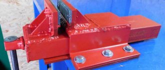
The so-called "butterfly"
This nickname was received due to the characteristic shape of the platform on which the inductors are located.
The arrangement of the elements is related to the operating principle. The circuit is made in the form of two generators operating at the same frequency. When identical coils are connected to them, an induction balance is created. As soon as a foreign object with electrical conductivity gets into the electromagnetic field, the balance of the field is destroyed.
Generators are implemented on NE555 chips. The illustration shows a typical diagram of such a device.
The coil for the metal detector (there are two of them, in the diagram: L1 and L2) is made by hand from wire with a cross section of 0.5–0.7 mm². The ideal option is a transformer winding copper core in varnish insulation (removed from any unnecessary transformer). The characteristics do not have to be maintained with pinpoint precision, under one condition: the coils must be identical.
Approximate parameters: diameter 190 mm, each coil has exactly 30 turns. The assembled product must be monolithic. To do this, the turns are grabbed with a mounting thread and filled with transformer varnish. If this is not done, vibration of the turns will throw the circuit off balance.
Electrical diagram
There are two manufacturing options:
- given the small number of elements, you can assemble it on a breadboard by connecting the legs of the parts using conductors;
- For accuracy and reliability, it is better to etch the board according to the proposed drawing.
Any “snot-based” soldering can fail in the field, and you will be offended for wasting your time.
Just like a transistor metal detector, the NE555 device needs fine tuning before use. The diagram shows three variable resistors:
- R1 is designed to adjust the frequency of the generator and achieve that same balance;
- R2 coarsely adjusts sensitivity;
- Using resistor R3, you can set the sensitivity with an accuracy of 1 cm.
Information: This scheme cannot discriminate against metals. The seeker only makes it clear that the object exists. And by the tone of the signal (based on your experience) you can determine the approximate volume and depth of the deposit.
The power supply is quite universal: 9–12 volts. You can select a battery from an uninterruptible power supply, or assemble a power supply from AAA batteries. A good option is 18650 batteries (they are also used for vaping).
Butterfly setting
The principle of operation is described above, so let’s just look at the technology. We set all resistors to the middle position, and ensure that the synchronization of the generators is disrupted. To do this, we fold the coils in a figure eight and move them relative to each other until the squeaking turns into crackling. This is a synchronization failure.
Read also: Monitor cable connector
We fix the rings and rotate the resistor R1 until a steady crackling sound appears at even intervals.
By bringing metal objects to the place where the coils overlap (this is the search point), achieve a steady squeak. The sensitivity is adjusted by resistor R2.
All that remains is adjustment with resistor R3, which is used rather to correct the voltage drop in the power source.
Mechanical part
A do-it-yourself metal detector rod is made from a lightweight plastic pipe or wood. The use of aluminum is undesirable as it will interfere with operation. The circuit and controls can be hidden in a sealed housing (for example, a junction box for wiring).
The butterfly finder is ready to go.
Detailed instructions for the Terminator 3 metal detector with your own hands
This type of design is designed to search for coins. The process of assembling it is completely simple. However, experience in assembling such a tool is still necessary. The Terminator is able to detect an object even if the target of capture is minimal.
To begin, you should prepare the necessary equipment, namely:
- a multimeter that measures speed.
- LC meter
- Oscilloscope.
Next, you need to find a diagram broken down into nodes. Now you can make a printed circuit board into which jumpers, resistors, panels for microcircuits and other parts should be soldered in order. The next step is to clean the board with alcohol.
. It is definitely worth checking for defects. You can check whether the board is in working condition as follows:
- Turn on the power.
- Turn down the sensitivity control until no sound is heard from the speaker.
- Touch the sensor connector with your fingers.
- When turned on, the LED should blink and then go out.
If all actions occurred, then everything was done correctly. Now you can make a coil. It is necessary to prepare a winding enamel wire with a diameter of 0.4 mm, which must be folded in half. A circle is drawn on a sheet of plywood with a diameter of 200 mm and 100 mm. Now you need to drive nails in a circle, the distance between them should be 1 cm.
Next, you can move on to winding the turns. At 200 mm you should make 30 of them, and at 100 - 48. Then the first coil should be soaked in varnish; when it dries, you can wrap it with thread. The thread can be removed, and by soldering the middle, you get a solid winding of 60 turns. Afterwards, the coil must be wrapped quite tightly with electrical tape.
. And a 1 cm foil is placed on top, this will be a screen, and more electrical tape is wound on top of it. The ends should come out.
On the second coil it is also necessary to solder the middle. In order to start the generator, you need to connect the first coil to the board. The second coil should be wrapped with a wire of 20 turns, then we connect it to the board. Now you need to connect the oscilloscope minus to minus to the board, and the plus is connected to the coil. Be sure to look at what frequency it will be when you turn it on and remember it or write it down on paper.
Now the coils need to be placed in a special mold so that they can then be filled with resin. Next, the oscilloscope is connected to the board, with the negative pole, the amplitude should reach zero. The coils in the mold are filled with resin to approximately half the depth. When everything is ready, the metal discrimination scale is adjusted.
Parts list for the Terminator 3 metal detector
As parts for the trio metal detector you will need:
If you have these parts, you can assemble the Terminator Pro metal detector yourself.
Impressions about the device
The metal detector pleases with its stable operation. It is simple and easy to use and is one of the most economical devices of this type. Not at all demanding on settings.
Minuses
In reality, the device is able to distinguish only minor debris; chains of precious metals are difficult for it to detect.
pros
Despite the presence of shortcomings, this pulse metal detector can rightfully be called outstanding among those assembled with one’s own hands. The main advantage of Chance is its selectivity, which showed itself quite well in real cops, and stability over long-term use.
It will be interesting➡ Do-it-yourself pirate metal detector (detailed instructions)
Types of MI by purpose
In accordance with their intended purpose, MI is divided into the following types:
- Soil models designed for underground surveys in the upper layers of soil. Devices in this category are the most common among metal detectors and treasure hunters who can assemble a metal detector with their own hands at home. The simplest homemade product has low accuracy and does not always distinguish between different types of metals. Professional instruments can detect small grains of gold, ignoring other metals.
- Depth models designed to detect targets at a depth of up to 6 meters. However, they can only “see” large objects with an area of over 400 square meters. see. Deep devices are in demand by engineering services as route finders, by geologists as specialized georadars for searching for native gold, etc.
- Underwater metal detecting devices operating underwater. They are subject to increased requirements for the tightness of the search system. The operating conditions of underwater MI in sea and fresh water differ significantly. Underwater detectors use only sound indication.
Note! Underwater MI can be used on the surface in the mode of a conventional ground metal detector. Searchers only need to adjust the length of the rod and the position of the stop to make it more convenient to use the device
- Special metal detectors:
- security devices for detecting metal products in luggage, clothing or on a person’s body during inspection;
- industrial metal detectors as part of conveyor lines, signaling the presence of metals in products;
- military devices, collectively called mine detectors;
- detectors tuned exclusively to gold objects.
In Fig. Below is a hand-held security metal detector.
Video on the topic
Once upon a time, having built several metal detectors of varying degrees of performance with my own hands, I wanted to study how the Arduino circuit works in this direction.
There are several good examples of how to assemble a metal detector with your own hands. However, they usually either require quite a lot of external components to process the analog signal, or the output sensitivity is quite weak.
When we think about pulsed metal detectors, the main topic is how to detect small voltage changes in the signals associated with the search coil. These changes are usually very small. The most obvious approach is to use the ATmega328 analog inputs. But looking at the specs, there are two main problems: they are mostly slow, and the resolution is (in most cases) low.
On the other hand, a microcontroller-based metal detector operates at 16 MHz and has pretty good timing capabilities, namely a resolution of 0.0625 µs when using the clock frequency. So, rather than using an analog input for readout, the simplest way to sense small dynamic voltage changes is to compare the change in voltage drop over time at a fixed reference voltage.
For this purpose, ATmega328 has suitable internal comparator features between D6 and D7. This comparator is capable of triggering an interrupt, allowing events to be processed accurately. Using this along with neatly coded timing routines like millis() and micos(), and using the ATmega328's much higher resolution internal timer, the Arduino is an excellent basis for this kind of metal detector.
So, speaking of the source code - a good start would be to program the internal comparator to "flip" the polarity of the inputs and use the internal counter as fast as possible to change the frequency of the changes.
The final code for Arduino:
Of course, this idea is not entirely new. The bulk of this code may be different. Try searching other sources, such as TPIMD.
Do-it-yourself simple metal detector
The metal detector circuit is not complicated, and you can find it either on the vast world wide web or in specialized literature. Above is a list of radio elements that are useful for assembling a metal detector with your own hands at home. You can assemble a simple metal detector with your own hands using a soldering iron or other available method. The main thing is that the parts should not touch the body of the device. To ensure the operation of the assembled metal detector, power supplies of 9 - 12 volts are used.
To wind the coil, use a wire with a cross-sectional diameter within 0.3 mm; of course, this will depend on the chosen circuit. By the way, the wound coil must be protected from exposure to extraneous radiation. To do this, shield it with your own hands using ordinary food foil.
The simplest metal detector at home
Diagram of a beat metal detector.
The circuit itself (see below) was redesigned and optimized by me from two metal detector circuits . These are “ Metal detector on a chip ” - Radio magazine, 1987, No. 01, pp. 4, 49 and “ High sensitivity metal detector ” - Radio magazine, 1994, No. 10, p. 26.
The result is a simple and functional circuit that provides stable low-frequency resulting beats - what is needed to determine by ear the slightest changes in frequency.
Functional and technical parameters of metal detectors
Before purchasing a high-quality metal detector, you need to decide on the search environment. It is necessary to take into account the potential dimensions of the desired objects and the depth of their occurrence. Key indicators that are emphasized when purchasing a device:
- principle of influence;
- frequency;
- susceptibility;
- weight;
- soil balancing;
- target designation;
- discriminator;
- auxiliary functionality.
The operating principle and operating frequency are the main indicators that determine the capabilities of the device and show which class it can be classified into.
There are deep products that are designed to detect objects at a depth of 5 m PHOTO: bestvix.ru