Versions of pressure gauges for resistance to vibration
| Performance group | frequency Hz | Offset amplitude for frequency below transition frequency**, mm | Accelerations for frequencies above the transition frequency, m/s2 | Accommodation |
| L1 | 5 — 35 | 0,35 | — | Places protected from significant vibrations. Only low frequency vibrations may appear |
| L2 | 0,75 | — | ||
| LX | — | — | ||
| (L3)* | (5 — 25)* | (0,1)* | — | |
| N1 | 10 — 55 | 0,15 | — | Places subject to vibration from operating machinery. Typical placement at industrial facilities |
| N2 | 0,35 | — | ||
| NX | — | — | ||
| (N3)* | (5 — 80)* | (0,075)* | (9,8)* | |
| (N4)* | (0,15)* | (19,6)* | ||
| V1 | 10 — 150 | 0,075 | 9,8 | Places in industrial facilities where there is vibration with a frequency exceeding 55 Hz |
| V2 | 0,15 | 19,6 | ||
| V3 | 0,35 | 49,0 | ||
| VX | — | — | ||
| (V4)* | (5 — 120)* | (0,15)* | (19,6)* | |
| (V5)* | (0,2)* | (29,4)* | ||
| F1 | 10 — 500 | 0,075 | 9,8 | Places located near premises in which operating aircraft engines are installed |
| F2 | 0,15 | 19,6 | ||
| F3 | 0,35 | 49,0 | ||
| FX | — | — | ||
| G1 | 10 — 2000 | 0,35 | 49,0 | Places located near premises in which operating aircraft engines are installed |
| G2 | 0,75 | 98,0 | ||
| GX | — | — | ||
| G3* | 5000* | 3,5* | 490,0* |
* At the request of the consumer. ** Transition frequency - 57 - 62 Hz
Analysis of industrial pressure gauges
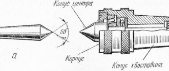
1. Instruments for measuring and regulating pressure. Purpose Pressure (p) is a physical scalar quantity measured by the ratio of the force acting perpendicular to the surface area to the area of this surface. Absolute pressure is pressure measured relative to absolute zero pressure or, in other words, absolute vacuum. Relative pressure (in compressor technology - excess pressure) is pressure measured relative to the earth's atmosphere. Devices for measuring total pressures are called pressure gauges; when we are talking about low pressures, the term vacuum gauges is also used, they are designed to measure: - absolute pressure; — excess (relative) pressure; — pressure difference; — vacuum pressure. Depending on their purpose, instruments for measuring pressure are divided into the following main groups: Pressure gauges - for measuring excess pressure. Absolute pressure gauge - for measuring pressure measured from absolute zero. Pressure and vacuum gauges - for measuring vacuum and excess pressure. Vacuum gauges - for measuring vacuum pressure (vacuum). Barometers - for measuring atmospheric pressure. Bar vacuum gauges - for measuring absolute pressure. Differential pressure gauges - for measuring pressure differences. The unit of pressure in the International System is the pascal (1 Pa). 1 Pa is the pressure produced by a force of 1 N acting on a surface of 1 m2 perpendicular to this surface (Appendix 1). Other extra-system units of pressure are also used: 1 at, 1 mm Hg. Art. 1 mmHg Art. — pressure exerted by a column of mercury 1 mm high. 1 atm is the pressure of the air column at sea level (760 mm Hg). The relationship between these units is given in table. 1
The pressure value can be measured from 0 (absolute pressure) or from atmospheric pressure (gauge pressure). If pressure is measured in technical atmospheres, then absolute pressure is designated as ata, and excess pressure as ati, for example, 9 ata, 8 ati. Gas Capacity Units Compressor performance is measured as the volume of gas compressed per unit of time. The basic unit used is cubic meter per minute (m3/min). The units used are l/min. Productivity is usually given either for conditions (gas pressure and temperature) of suction, or for normal conditions (pressure 1 atm., temperature 20 C). In the latter case, the letter “n” is placed in front of the unit of volume (for example, 5 nm3/min). In English-speaking countries, cubic foot per minute (CFM) is used as a unit of productivity. 1 CFM = 28.3168 l/min. = 0.02832 m3/min. 1 m3/min =35.314 CFM. The relationship between these units is given in table. 2 Table of ratios of performance measurement units:
Instruments for measuring and regulating pressure can be divided into: - instruments for measuring and regulating high pressure; — devices for measuring and regulating low pressure. High pressure is pressure more than 1 atm. Low pressure is pressure not exceeding 1 atm. The low pressure range is divided into low, medium, high and ultra-high vacuum (Fig. 1)
According to the principle of operation, all devices for measuring pressure can be divided into liquid, spring, deadweight and with remote transmission of readings. Devices in which the measured pressure is balanced by the weight of a liquid column, and the change in liquid levels in communicating vessels serves as a measure of pressure, are called liquid devices . This group includes cup and U-shaped pressure gauges, differential pressure gauges, etc. Deformation (spring) devices are devices in which the measured pressure is balanced by the elastic forces of a spring, the deformation of which serves as a measure of pressure. This group includes a variety of devices that differ in the type of springs (diaphragms, bellows, pressure tubes). Due to their simplicity of design and ease of use, spring devices are widely used in technology. Types of spring pressure devices: Spring-piston; Spring-diaphragm; Spring-bell; Spring-bellows. Weight-piston devices are devices in which the measured pressure is balanced by the force created by calibrated weights acting on a piston freely moving in the cylinder. Devices with remote transmission of readings include devices that use changes in certain electrical properties of a substance (electrical resistance of conductors, electrical capacitance, the appearance of electrical charges on the surface of crystalline minerals, etc.) under the influence of the measured pressure. Such devices include manganin resistance pressure gauges, piezoelectric pressure gauges using quartz crystals, tourmaline or Rochelle salt, capacitive pressure gauges, ionization pressure gauges, etc. According to the method of measuring pressure, devices are divided into: - mechanical; - electronic. Today there are about 100 mechanical instruments for measuring and regulating pressure, a complete list of instruments is given in Appendix 2. Based on the registration principle, the entire group of pressure gauges is divided into: - direct-acting pressure gauges; — for indirect-acting pressure gauges. Liquid, compressor and deformation pressure gauges are classified as direct-acting pressure gauges. They directly measure gas pressure. Their readings are fundamentally independent of the composition of the gas and can only indirectly depend on temperature. Indirect pressure gauges do not measure pressure itself, but rather some function of it. Their readings depend on the type of gas and its temperature. Accuracy classes According to their metrological purpose, measuring instruments are divided into standard and working. Exemplary measuring instruments are devices intended for verification of other measuring instruments. Working measuring instruments are all measuring instruments used for direct measurements. The degree of accuracy of the instruments formed the basis for their division into classes. The accuracy class of measuring instruments is characterized by the level of permissible error. Accuracy class is a value characterizing the main permissible reduced error of the device. It expresses as a percentage the ratio of the greatest permissible absolute error of a device under normal operating conditions to its nominal value. Standard pressure gauges have the following accuracy classes: deadweight pressure gauges - 0.05; 0.2; spring pressure gauges - 00.16; 2.5; 0.4. Working pressure gauges have accuracy classes - 0.5; 1; 1.5; 2.5; 4. The choice of one or another measurement method depends on the nature of the quantity being measured, the required measurement accuracy and the measuring equipment. No matter how perfect the measuring instruments and measurement methods are, they still provide only approximate values of the measured quantities. Deviations of measurement results from the actual value of the measured quantity are called measurement error. The actual value of the measured quantity is taken to be the value measured by the reference device. The permissible error is the largest error in the instrument reading allowed by the standards. When classifying instruments according to the degree of accuracy, two types of errors are distinguished - basic and additional. The main error of a device is its error under normal conditions, when external unfavorable factors are absent or their influence is minimized. This error is due to imperfections in the design and assembly of the device; its main factors are: friction in the supports of the moving part, inaccuracy of calibration and drawing of the scale. Additional error is the indication error caused by the influence of external conditions on the device when deviating from normal operating conditions, namely: ambient temperature, air humidity, vibration, shaking, etc. The main characteristics also include variations in readings. The variation in the readings of a measuring device is the largest found experimental difference between repeated readings of a measuring device corresponding to the same actual value of the quantity measured by it under constant external conditions. In indicating instruments, variation can be detected by making a series of observations, changing the actual value of the measured value from the smallest to the largest, and then in the reverse order, and noting the instrument readings corresponding to these values. The reason for the variation is friction and backlash of the moving parts of the device mechanism, incomplete elasticity of springs and other parts subject to forces that change their shape or size. The variation is more pronounced in instruments having a mechanism, but it also exists in other instruments, such as liquid thermometers and pressure gauges, where the resistance of the fluid to movement causes a lag in the reading. Methods for measuring pressure are based mainly on balancing the existing forces using a column of liquid or due to the deformation of various types of springs. Distribution of industrial pressure gauges by industry Instruments for measuring and monitoring pressure are widely used in industries such as oil, gas and many others. The distribution of industrial pressure gauges by industry is shown in Fig. 2. Due to certain requirements for pressure gauges in certain industries, such as aircraft manufacturing, the chemical industry, as well as the insignificant use of pressure gauges in industries such as food, energy, and metallurgy, these industries will not be considered in this study. Distribution of industrial pressure gauges by type in industries 1. The following types of pressure gauges are used in the oil industry: - for oil wells; — registering; — general purpose ranges: 0...6 MPa, 0...4 MPa, 0...25 MPa, 0...160 MPa 0...1.0 MPa; 0…6 MPa; 0…40 MPa 0…1.6 MPa; 0…10MPa; …60 MPa 0…2.5 MPa; 0…16 MPa; 0...100 MPa - vibration-resistant. 2. Gas industry: - general purpose; - differential. 3. Automotive industry: - for brake systems: 0...10 MPa - for automobile pumps (casing bore diameter - 44 mm) 0...4 kgf/cm2 0...6 kgf/cm2 - in car pneumatic systems (casing bore diameter - 60 mm) 0 ...6 kgf/cm2 - in tractors: 0...6 kgf/cm2 - general purpose 4. Shipbuilding: - ship 0...100 kgf/cm2 160...600 kgf/cm2 - ship -1...0...1.5...9 kgf/ cm2 - general purpose 5. Water systems - general purpose - vibration-resistant 6. Railway transport - railway 0...6 kgf/cm2 0...10 kgf/cm2 0...16 kgf/cm2 7. Aircraft construction - aviation two-pointer (0...16 kgf/cm2 ) 8. Food industry: - dairy (polyethylsiloxane liquid filler) 0...10 kgf/cm2 (Accuracy class 5) 9. Chemical industry: - ammonia 0...100 kgf/cm2 over 160 kgf/cm2 - corrosive
High pressure gauges (HP) Oil industry 1. Refinery - 30 pcs. [1] Refineries account for an average of 500 units. Ministry of Internal Affairs 30 x 500 = 15,000 pcs. 2. Oil depots - 900 pcs. [1] There are an average of 500 units per oil depot. Ministry of Internal Affairs 900 x 500 = 450,000 pcs. 3. Gas stations - 70,000 pcs. Number of Ministry of Internal Affairs - 10 70 000 x 10 = 700 000 pcs. 4. Fuel trucks (Based on the assumption that one fuel truck serves two gas stations) 70,000/2 = 35,000 pcs. Ministry of Internal Affairs - 2 pcs. 35,000 x 2 = 70,000 Total, the oil industry accounts for an average of 15,000 + 450,000 + 700,000 + 70,000 = 1,235,000 units. Gas industry 1. Automobile gas. [2] Cars - 400,000 Number of Ministry of Internal Affairs - on average 5 units. 400,000 x 5 = 2,000,000 pcs. 2. Gas control points - 100 GRS - 1000 Number of MIA in one GRS - minimum 2 pcs. 100 x 1000 x 2 = 200,000 pcs. 3. AGCS - 230 [3] Ministry of Internal Affairs on average per AGS - 25 pcs. 230 x 25 = 5750 pcs. 4. Household gas equipment gas boilers -250,000 pcs.[4] Ministry of Internal Affairs minimum 2,250,000 x 2 = 500,000 pcs. 5. Devices for gas welding equipment - 500,000 pcs. Ministry of Internal Affairs at least 1 piece. 500,000 x 1 = 500,000 pcs. 6. Tanker trucks (gas) - 108 (Based on the calculation that one tank truck serves 2 gas filling stations) Ministry of Internal Affairs minimum 2,108 x 2 = 316 pcs. In total, the gas industry accounts for an average of 2,000,000 + 200,000 + 5,750 + 500,000 + 316 = 2,706,066 units. Automotive industry 1. Car - 1,164,667 units/year [5] Number of Ministry of Internal Affairs - on average 5 units. 1,164,667 x 5 = 5,823,335 pcs. 2. Equipment for inflating gas station tires - 70,000 AGKS -208 At every second gas station, tire fitting is carried out using special equipment. equipment (70,000 + 208)0.5 = 35,104 Ministry of Internal Affairs - minimum 1,35,104 x 1 = 35,104 pcs. In total, the automotive industry accounts for an average of 5,823,335 + 35,104 = 5,858,439 units. Water systems 1. Boiler rooms - 68,000 pcs. Ministry of Internal Affairs - on average 10 pieces. 68,000 x 10 = 680,000 pcs. Railway transport railway cars - 850,000 trams - 12,500 metro cars - 5791 Locomotives 20,000 pcs. (wear 70%) Ministry of Internal Affairs on average 3 (850,000 + 12,500 + 5791 + 20,000) x 3 = 2,664,873 pcs. For replacement, based on replacement in each transport, 2 pieces. (850,000 + 12,500 + 5,791 + 20,000) x 2 = 1,776,582 pcs. Total railway transport accounts for an average of 2,664,873 + 1,776,582 = 4,441,455 units. According to preliminary estimates, when segmenting the market for pressure measuring devices, it was revealed that the largest number of devices falls on the following segments: 1. in the automotive industry - 5,858,439 units. 2. for railway transport - 4,441,455 pcs. 3. for the gas industry - 2,706,066 units. 4. for the oil industry - 1,235,000 units. 5. for water systems - 680,000 pcs. Checking preliminary data Automotive industry During the study, it was revealed that cars mainly use various sensors* (Table 3), which do not belong to the category of industrial high-pressure pressure gauges. SENSOR - an element of a measuring, signaling, regulating or control device that converts a control value (pressure, temperature, frequency, speed, light intensity, voltage, electric current, etc.) into a signal convenient for measurement, transmission, storage, registration and impact on controlled processes.
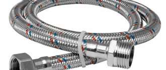
In the automotive industry, high-pressure pressure gauges are used to check and adjust fuel supply pressure, as well as pump performance in cars; as a rule, these are control pressure gauges with fittings, hoses and a valve, the pressure gauge scale is up to 6 kgf/cm2. Brake systems use trace pressure gauges. ranges:
Thus, the market capacity of high-pressure pressure gauges in the automotive industry, taking into account the adjustments, will be: 170,408 x 2 = 340,816 (where 170,408 is the annual production of trucks, 2 - MIA) 64,812 x 2 = 129,624 (where 64,812 is the annual production of buses , 2 - Ministry of Internal Affairs) 70,000 x 1 = 70,000 (where 70,000 is the number of gas stations, 1 - Ministry of Internal Affairs) 208 x 1 = 208 (where 208 is the number of gas stations, 1 - Ministry of Internal Affairs) 25,000 x 1 = 25,000 (individual use ) TOTAL: 340,816 + 129,624 + 70,000 + 208 + 25,000 = 565,648 Ministry of Internal Affairs Thus, the preliminary estimate was inflated by 10 times. Car manufacturing Railway transport railway cars - 850,000 pcs. tram - 12,500 pcs. metro car - 5791 pcs. Locomotives 20,000 pcs. (70% wear) Ministry of Internal Affairs on average 3 (12,500 + 5791 + 20,000) x 3 = 114,873 pcs. For replacement, based on replacement in each transport, 2 pieces. (12500 + 5791 + 20,000) x 2 = 76,582 pcs. Total railway transport accounts for an average of 114,873 + 76,582 = 191,455 units. Thus, the preliminary estimate was overestimated by 23 times.
References 1. Doug Harris “Oil refining in Russia and Ukraine” 08/23/2004 2. Vasyukov G.V. Some aspects of ensuring fire safety of storage facilities, maintenance and repair of gas-cylinder vehicles. 2004 3. Publishing House "Oil and Capital" dated July 12, 2005 "Natural gas and automobile" 4. Ponomarev "Russian market of domestic gas boilers" 5. Let's try. Ru dated 12.2004 “Car production in Russia increased by 9.6%” 6. Automotive gas filling compressor stations 7. https://kipovez.nm.ru/poverca/prdavl/obcv.html General information about pressure devices. Characteristics and classification of devices. 8. GOST 2405-88 Pressure gauges, vacuum gauges, pressure and vacuum gauges, pressure gauges, draft gauges and draft pressure gauges. General technical conditions 9. Bulletin of the Accounts Chamber of the Russian Federation No. 8 (80) / 2004 “Data on the number of metro cars for all operating subways in the Russian Federation” 10. Starikovskaya S. M. Physical research methods. Seminar classes. Part 1. Moscow 2001 11. https:// www.lbmvac.ru Table of relationships between the main units of pressure measurement. Appendix 1 Table of standard pressure sizes
Appendix 2 Mechanical instruments for measuring and regulating pressure Vacuum gauges Sensors 1. Height sensors 2. Dynamic pressure sensors 3. Pressure sensors for limiting (extreme) conditions 4. Miniature and subminiature pressure sensors 5. Programmable pressure sensors 6. Pressure sensors with data output in the form graphic curve 7. Pressure sensors with output signal amplification 8. Pressure sensors with high-speed, instantaneous indication 9. Sensors with extrusion pressure indication 10. Compression and extension sensors 11. Gas and oxygen pressure reduction sensors 12. Reference sensors for calibrating pressure gauges Sensors and primary pressure transducers 1. Absolute pressure sensors and primary transducers 2. Vacuum pressure sensors and primary transducers 3. Bidirectional (two-way) pressure sensors and primary transducers 4. Differential pressure sensors and primary transducers 5. Liquid pressure sensors and primary transducers 6. Sensors and primary pressure transducers relative (comparative) pressure transducers 7. Sensors and primary transducers of manometric, excess pressure Dampers (absorbers) of pressure fluctuations for pressure gauges Pressure gauges 1. U-shaped and double-jointed pressure gauges for two types of liquids 2. Differential pressure gauges (differential pressure gauges) 3. Pressure gauges for measuring absolute pressure 4. Pressure gauges for measuring positive (excess) pressure 5. Pressure gauges for oil wells 6. Pressure gauges for polymers 7. Pressure gauges for liquefied gases in cylinders 8. Pressure gauges for refrigerants 9. Ship pressure gauges 10. Railway pressure gauges 11. Ionization pressure gauges (ionization vacuum gauges ) 12. Combined pressure gauges for measuring excess pressure and vacuum (pressure and vacuum gauges) 13. Multi-leg pressure gauges 14. Inclined pressure gauges (with an inclined U-shaped tube) 15. Single-leg pressure gauges 16. Illuminated signal and warning pressure gauges 17. Portable pressure gauges 18. Precision pressure gauges 19 Precision pressure gauges for laboratories and the chemical industry 20. Pressure gauges with indication and registration (self-recording) 21. Electrical and electronic pressure gauges 22. Pressure gauges, pressure indicators 23. Manostats, pressure stabilizers 24. Micromanometers Equipment for measuring and monitoring pressure in portable fire extinguishers Equipment for pressure tests Manometric and vacuum signal and warning devices Regulators 1. Recorders, recorders for measuring pressure 2. Pressure regulators 3. Pressure regulators for food industry equipment 4. Manual pressure regulators 5. Pressure regulators with a controlled membrane 6. Electronic pressure regulators 7. Pressure regulators and reducers for air 8. Pressure regulators and reducers for gases 9. Pressure regulators and reducers for liquids Pressure switches for refrigeration units Stands for calibrating pressure gauges, pressure measuring instruments Tubes for pressure gauges Traction meters Diaphragm seals for pressure measuring instruments in liquid aggressive media Pressure gauge protection devices Pressure control devices Gas pressure regulation devices for gas generating units Pressure standards ZAO Medtekhnika 198516, St. Petersburg, Petrodvorets, st. Factory building No. 1 Telephone; fax e-mail
Markings of explosion-proof pressure gauges
| 0 | Ex | ias | IIC | T3 | |
| 1 | 2 | 3 | 4 | 5 | 6 |
1. Explosion protection level: for group I: RP - for electrical equipment of increased reliability against explosion; РВ - for explosion-proof electrical equipment; RO - for especially explosion-proof electrical equipment; for group II: 2 - for electrical equipment of increased reliability against explosion; 1 - for explosion-proof electrical equipment; 0 - for especially explosion-proof electrical equipment.
2. Ex mark indicating that the electrical equipment complies with explosion protection standards.
3. Designation of the type of explosion protection: o - oil filling of the shell; p - filling or purging of the shell under excess pressure; q—quartz filling of the shell; d - explosion-proof shell; e - type “e” protection; ia — intrinsic safety, level “ia” (category “ia”); ib — intrinsic safety, level “ib” (category “ib”); ic — intrinsic safety, level “ic” (category “ic”); m - sealing with compound; n – protection type “n”; s - special type of explosion protection. After the main type of protection, an additional one may be indicated.
4. Designation of the electrical equipment group: I - for electrical equipment intended for underground workings of mines and mines and their surface structures, hazardous due to firedamp gas or dust; II or IIA, or IIB or IIC - for indoor and outdoor electrical equipment intended for use in places with a potentially explosive gas environment, except for mines and their surface structures hazardous for firedamp. The letters A, B, C should be used to designate subgroups of EO when using types of protection “d” and “i”.
5. For electrical equipment of group II - the designation of the temperature class, or the maximum surface temperature. T1 = 450 °C; T2 = 300 °C; T3 = 200 °C; T4 = 135 °C; T5 = 100 °C; T6 = 85 °C.
6. Additional marking (if necessary): X (or warning notice) - special conditions are required to ensure safety during operation; U - This device is a component of Ex equipment.
On the selection, installation and operation of pressure gauges and thermoses in heat supply systems
There are a number of mandatory requirements for the selection, installation and operation of pressure gauges and thermometers in heat supply systems. Let's look at the main ones.
Ambient air temperature, humidity, vibration, dust in places where instruments and equipment are installed must be within the limits allowed by standards, technical specifications and passports for this equipment.
When selecting ranges and measurements:
— the working pressure measured by the pressure gauge must be in the range from 1/3 to 2/3 of the measurement scale;
— the upper limit of the scale of recording and indicating thermometers must be equal to the maximum temperature of the medium being measured.
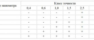
It is also worth paying attention to the accuracy class of the device, that is, the permissible percentage of measurement error from the scale. For example, when conducting hydraulic tests in heating, ventilation and hot water supply systems, spring pressure gauges with an accuracy class of at least 1.5 must be used. this means that the permissible error of the pressure gauge is 1.5% of the measurement scale.
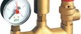
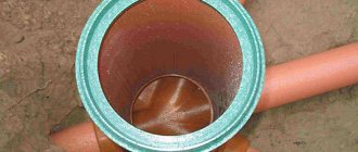
Pressure gauges installed on pipelines with coolant temperatures up to 105 °C inclusive must be connected through a three-way valve. Pressure gauges installed on pipelines with a coolant temperature above 105 °C must be connected through a siphon tube and a three-way valve. The pressure gauge is placed and illuminated in such a way that its readings are convenient for maintenance personnel to observe. The diameter of pressure gauge housings installed from the level of the observation platform at a height of 2 m must be at least 100 mm, at a height from 2 to 3 m at least 1600 mm and at a height from 3 to 5 m at least 250 mm. If the pressure gauge is located at a height of more than 5 m, a backup pressure gauge is installed at a lower elevation.
Thermometers on pipelines must be installed in sleeves, and the protruding part of the thermometer must be protected by a frame. on pipelines with a nominal diameter of up to 40 mm inclusive, an expander with a diameter of at least 50 mm should be provided at the location where thermometers are installed.
Thermometer sleeves should be installed:
- on pipelines with a diameter of 70-200 mm - obliquely to the pipeline axis against the flow;
- on pipelines with a diameter of less than 70 mm - in special expanders;
- on pipelines with a diameter of more than 200 mm - perpendicular to the axis of the pipeline.
The immersion depth of the sleeve should be equal to:
- for pipelines with a diameter of less than 200 mm - 2/3 of the pipeline diameter;
- for pipelines with a diameter of more than 200 mm - 1/2 of the pipeline diameter.
Places required for installation of pressure gauges and thermometers for consumers with a maximum hourly load of up to 2.3 MW (1.978 Gcal/h):
a) pressure gauges showing:
— after shut-off valves at the entrance to the heating point of pipelines of water heating networks, steam pipelines and condensate pipelines;
— before and after pressure regulators on pipelines of water heating networks and steam pipelines;
— on steam pipelines before and after pressure reducing valves;
- on the supply pipelines after the shut-off valves on each branch to the heat consumption systems and on the return pipelines to the shut-off valves - from the heat consumption systems;
b) fittings for pressure gauges:
- to the shut-off valves at the entrance to the heating point of pipelines of water heating networks, steam pipelines and condensate pipelines;
— before and after mud traps, filters and water meters;
c) thermometers showing:
— after shut-off valves at the entrance to the heating point of pipelines of water heating networks, steam pipelines and condensate pipelines;
— on pipelines of water heating networks after the mixing unit;
— on return pipelines from heat consumption systems along the flow of water in front of the valves;
d) thermometers recording meters - on the supply and return pipelines;
e) flow meters or water meters - on the pipelines of primary and secondary coolants;
f) indicating thermometers and pressure gauges must be provided at the inlet and outlet of heating and heated water pipelines for each stage of water heaters of hot water supply and heating systems;
g) indicating pressure gauges should be provided before the suction and after the discharge pipes of the pumps.
Measuring instruments used at heating installations and in heating networks must be registered in the State Register of Measuring Instruments of the Republic of Belarus and operated in accordance with the requirements of the Law of the Republic of Belarus 05.09. 1995 No. 3848-XII “On ensuring the uniformity of measurements.”
In installation locations not specified above (not required for installation in accordance with TKP 458-2012 “Rules for the technical operation of heating installations and consumer heating networks”), owners of pressure gauges can transfer them to the category of indicators by means of administrative documents with independent determination of the verification interval.
It is prohibited to use pressure gauges and thermometers if:
— there is no seal or verification stamp, the verification period has expired;
— there is mechanical damage to the body/glass of the device or the connection fitting - for pressure gauges, sleeves and frames for thermometers;
— when removing pressure from the pressure gauge, the working pointer does not return to the zero mark of the scale by an amount exceeding half the minimum permissible measurement error for a specific pressure gauge;
— the permissible value of the measurement error of the device is exceeded;
— there are other damages that may affect the accuracy of the instrument readings.