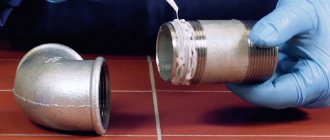
Types of thread
As already noted, all types of joints of this class are standardized. For example, GOST 24705-2004 determines the dimensions of a metric profile, in particular, the angle at the base, pitch, etc. In total, about 15 domestic and foreign standards are classified as metric.
Download GOST 24705-2004
There is also a classification of joints of this type. It is performed based on its geometric dimensions, location on the product and number of passes, or based on its practical use.
Below is a list showing the types of detachable connection designs and their designations:
- metric (M);
- metric conical (MK);
- cylindrical (MJ);
- cylindrical pipe (G);
- pipe conical (R);
- round for sanitary fittings (Kr);
- trapezoidal (Tr);
- persistent (S);
- persistent reinforced (S45°);
- edison round (E);
- metric (EG-M);
- inch cylindrical (UTS: UNC, UNF, UNEF, 8UN, UNS);
- inch (BSW);
- inch tapered (NPT);
- oil assortment.
Pipe inch thread
All these structural elements are used in all industries, ranging from aviation to food.
Metric thread
Metric is performed on the basis of GOST 8724-2002 - most often used in the manufacture of fasteners. Subject to certain conditions, this type can be used as a chassis.
Download GOST 8724-2002
This type is based on an equilateral triangle (with a base angle of 60 degrees). It may have one or more entries. Multi-entry is used in cases where it is necessary to ensure increased strength of joint joints.
Domestic and foreign manufacturers produce products with a diameter from 0.25 to 600 mm and a pitch from 0.25 to 6 mm. Products with a small pitch are used when it is necessary to ensure detachable assembly of products with a thin wall. By the way, this type is used quite often in the automotive industry. It can be left-handed or right-handed.
Metric thread
It is designated as follows - the letter is indicated in the first place, in this case it is M. Then, its nominal size and pitch are shown; for this type, the designation is used only in mm. In addition, the designation of parameters includes the number of passes and execution (left or right). Of course, the manufacturing tolerance must be indicated. The M12*1 marking indicates that it has a nominal diameter of 12 mm and a pitch of 1.
Thread direction
An important characteristic describing the parameters of a metric thread is its direction. It characterizes the orientation of the helix that forms the turns. By direction, threaded connections are classified into:
- rights;
- left.
The table provides a brief description of the directions.
| Thread direction | Description | Scope of application |
| Right | · the protrusion moves clockwise away from the observer when rotating; · the nut must be rotated clockwise to screw onto the screw. | Widely used in mechanical engineering, the most common type of fastening connections |
| Left | · the protrusion moves counterclockwise from the observer when rotating; · the nut should be rotated counterclockwise in order to screw onto the screw. | It is rarely used, for example, for parts that rotate to the left during operation: · studs for fastening left wheels in a car; · in bicycles, the ratchet cap is screwed to the left and the left pedal is screwed into the connecting rod; · when tied with a lanyard; · in cylinders, the work with which requires monitoring the volume of gas (propane cylinders); · in some unique products to protect the buyer from purchasing counterfeit products |
All fasteners with left-hand threads are specially marked.
The letter “L” is marked on the bolts at the end of the hexagon. On the heels, the letter “L” is also printed on the end. Fittings and nuts are marked with two grooves cut on a hexagon.
Inch thread
This class is used mostly when creating detachable joints of pipeline fittings (pipes, taps, valves, etc.). It is applied to products made of metal and plastic. Key parameters are defined in GOST 6111-52. It contains tables that define dimensions, steps and tolerances. All dimensions and symbols are given in inches.
Download GOST 6111-52
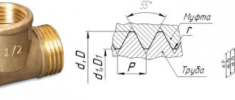
At the base of this view is a triangle with an apex angle of 55 degrees. As with the metric top and bottom, the tops and bottoms have been removed.
Inch thread
Manufacturers produce parts with a pipe profile from 3/16 (4.8 mm) to 4 (101 mm) inches.
Definition of thread type
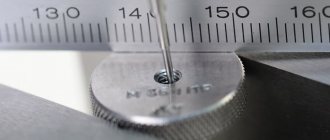
An experienced mechanic can determine the type of thread visually, but the parameters can only be fully determined using a caliper and a calculator or a special metal template. When using a measuring tool, the obtained data is recalculated and compared with tabular values.
The templates are marked to indicate the type of thread. If in doubt, it is necessary to carry out a control measurement with a caliper and identify the cutting according to the tables.
Russian industry produces templates of 2 types (with markings M60° for metric profiles with an angle of 60° and D55°, intended for identifying inch or pipe cutting with an apex angle of 55°). Metal templates are collected in a common pack on the central axis. Each element is painted or pressed with a number indicating the thread pitch (in mm or inches, depending on the type of templates).
This is interesting: Soldering stainless steel: features, technology and advice from professionals. Selecting solder for soldering
Metric tapered thread
The difference between a conical product and an ordinary metric one is that it is applied to a conical internal or external surface. In this case, the cone angle is 1:16.
It is used in cases where it is necessary to ensure the tightness of the connection. For example, in pipeline systems designed to transport liquids.
Manufacturers producing products of this type are guided by the requirements of GOST 25229-85.
Metric tapered thread
To designate a metric conical profile, the letter abbreviation MK is used. Next, indicate all the necessary geometric parameters. For example, MK 24*1.5 shows that it has an outer diameter of 24 mm and a pitch of 1.5.
MAIN THREAD ELEMENTS
Organization of a mechanic's workplace
4.1 BASIC THREAD ELEMENTS
Any thread has the following main elements: profile; profile angle and height; step; outer, middle and inner thread diameters.
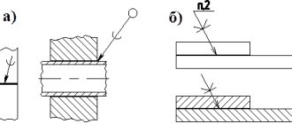
The thread profile (Fig. 257) is considered in the section passing through the axis of the bolt or nut. A thread (turn) is the part of the thread formed during one full revolution of the profile.
Profile angle α is the angle between the sides (edges) of the thread profile, measured in a plane passing through the axis of the bolt. In metric threads this angle is 60°, in inch threads it is 55°.
Height (depth, thread) H of the profile is the distance from the top of the thread to the base of the profile, measured perpendicular to the axis of the bolt.
Thread pitch P is the distance between the parallel sides or vertices of two adjacent turns, measured along the axis of the thread. Rice. 257. Basic thread elements
In metric threads, the pitch is expressed in millimeters; inch thread is characterized by the number of threads (turns) per inch.
The outer diameter d of the thread is the diameter of the cylinder described near the threaded surface. The outer diameter is measured for bolts at the tops of the thread profile, for nuts - at the valleys.
The internal diameter d of the thread is the diameter of the cylinder inscribed in the threaded surface. The internal diameter is measured for bolts at the recesses, for nuts - at the tops of the thread profile.
The average diameter d of the thread is the diameter of a cylinder coaxial with the thread, the generatrices of which are divided by the side sides of the profile into equal segments.
4.2 THREAD PROFILES
The thread profile depends on the shape of the cutting part of the tool with which the thread is cut.
Most often, a cylindrical triangular thread is used (Fig. 258a); It is usually called fastener because it is cut onto fasteners such as studs, bolts and nuts.
Tapered triangular threads make it possible to obtain a tight connection. Such threads are found on conical plugs, sometimes in oilers.
Rectangular thread (Fig. 258, b) has a rectangular (square) profile. It is not standardized, difficult to manufacture, fragile and rarely used.
Trapezoidal tape thread (Fig. 258,c) has a trapezoidal cross-section with a profile angle of 30°. Its friction coefficient is low, so it is used to transmit movements or large forces in metal-cutting machines (lead screws), jacks, presses, etc. The turns of this thread have a large cross-section at the base, which ensures its high strength and ease of cutting. The main elements of trapezoidal threads are standardized.
The thrust thread (Fig. 258, d) has a profile in the form of an unequal trapezoid with a working angle at the apex equal to 30°. The bases of the turns are rounded, which provides a strong profile in dangerous sections. Therefore, this thread is used in cases where the screw must transmit a large one-sided force (in screw presses, jacks, etc.).
A round thread (Fig. 258, e) has a profile formed by two arcs associated with small straight sections and an angle of 30°. This thread is rarely used in mechanical engineering. It is used mainly in connections subject to heavy wear and in contaminated environments (fittings for fire pipelines, carriage ties, hooks of lifting machines, etc.). This thread is not standardized.
Based on the number of threads, threads are divided into single-start (single-start) and multi-start (multi-start). The thread stroke is the axial movement of the screw during one revolution. For single-start threads, the stroke is equal to the pitch (the distance between adjacent turns), and for multi-start threads, the product of the pitch and the number of starts.
The latter can be determined by looking at the end of the screw (nut); usually it is clearly visible how many threads originate from the end (Fig. 259, a, b). With a single-start thread, only one end of the thread is visible at the end of a screw or nut, while with multi-start threads, two, three or more are visible.
Drawing. 259. Types of threads depending on the number of starts: a - three-start,
b – eight-way
Single-start threads have small helix angles and greater friction (low efficiency). They are used where a reliable connection is required (in fasteners).
For multi-start threads, compared to single-start threads, the helix angle is significantly greater. Such threads are used in cases where rapid movement along the thread with the least friction is necessary, and in one turn of the screw (or nut), the nut (or screw) will move by the amount of stroke of the helical line of the thread. Multi-start threads are used in mechanisms used to transmit motion.
4.3 Main types of thread and their designation
In mechanical engineering, as a rule, three thread systems are used - metric, inch and pipe.
Metric thread (Fig. 260, a) has a triangular profile with flat-cut tops; The profile angle is 60°, diameters and pitch are expressed in millimeters.
Metric threads are divided into threads with normal pitch (for outer diameters 1...68 mm) and with fine pitches (for outer diameters 1...600mm).
Metric threads with normal pitch are designated M20 (the number is the outer diameter of the thread), with small pitches - M20X1.5 (the first number is the outer diameter, the second is the pitch).
Metric threads are used mainly as fastening threads: with a normal pitch - for heavy loads and for fasteners (bolts, nuts, screws), with fine pitches - for light loads and fine adjustments.
Inch thread (Fig. 260, b, d) has a triangular flat-cut profile with an angle of 55 ° (Whitworth thread) or 60 ° (Sellers thread). All dimensions of this thread are expressed in inches (1″ = 25.4 mm). Pitch is expressed as the number of threads (turns) per inch.
Inch threads with diameters from 3/16 to 4″ and the number of threads per 1″ are 24…3. The outer diameter of the thread is expressed in inches. Inch threads differ from metric threads in larger pitches.
In the USSR, when designing new structures, the use of inch threads is not permitted. It is used in the manufacture of spare parts for machinery and equipment obtained from countries where inch threads are used.
Pipe cylindrical thread (Fig. 260, c) is standardized, is a small inch thread, but unlike the latter, it mates without gaps (to increase the tightness of the connection) and has rounded tops.
The nominal diameter of the pipe thread is taken to be the internal diameter of the pipe (the diameter of the hole, or, as they say, the “clear diameter of the pipe”), i.e. the outer diameter of the pipe thread will be larger than the nominal diameter by twice the thickness of the pipe walls.
Cylindrical pipe threads are used for outer diameters 1/8…6″ with the number of threads per inch from 28 to 11; The profile angle is 55°. It is used on pipes to connect them, as well as on pipeline fittings and other thin-walled parts.
Cylindrical pipe threads are designated as: 3/4″ pipes (numbers are the nominal thread diameter in inches). Pipe threads with diameters from 1/8 to 6″ are standardized with the number of threads per inch from 28 to 11
Conclusion
This essay discussed: the design of a vertical milling machine, the principle of its operation; some types of cutters for processing shaped surfaces, classification of bench vices; One of the types of metal processing is filing.
References
1. N.I. Makienko. General plumbing course. M. 1984
2. P.M. Denezhny, G.M. Stiskin, I.E. Thor. Turning. M. 1976
3. B.G. Zaitsev, S.B. Rytsev. Handbook of a young turner. M. 1988
4. V.A. Slepinin. Metal turner training guide. M. 1974
5. Milling: Textbook for secondary vocational and technical schools - 3rd ed., revised. and additional - M.: Higher school, 1980.-208 p., ill. (Vocational education. Cutting).
Organization of a mechanic's workplace
Information about the work “Cutters, tools, cutting element, labor safety, lathe, cutter, plumbing, turning”
Section: Industry, production Number of characters with spaces: 37413 Number of tables: 0 Number of images: 7
Similar works
Turning
42108
0
1
ov of metal cutting, carried out on lathes. The parts processed on these machines are divided into three classes: shafts, disks, bushings. Parts are processed on specialized machines designed to process certain simple and medium-complexity workpieces or perform individual operations: cutting external and internal triangular and rectangular threads with taps...
Metalworking, mechanical, dismantling and installation work
66813
0
6
… . Therefore, a car enthusiast who wants to independently carry out more or less complex maintenance and repair operations on a car must acquire some more devices and tools. Plumbing and assembly tools. It is advisable to have a full range of open-end wrenches, preferably in duplicate. Combination and adjustable wrenches, special pliers for...
Development of a technological process for repairing the feed box of the 1M63N machine
56775
24
15
... ring gear, scuffed at the end Replacement of the worm gear (pressing on a new bushing with subsequent milling of the teeth) All other parts are suitable for further use. 5. DEVELOPMENT OF A TECHNOLOGICAL PROCESS FOR REPAIRING A PART 5.1 Information about the part being repaired, the choice of repair method and its justification During the defect detection process, some parts were rejected. One …
Development of technological processes for machining the primary shaft
129923
32
5
... Based on the above points of compliance of this assembly unit with all manufacturability standards, we conclude that the design of the primary shaft assembly in question is manufacturable. 3.3 Development of the assembly technological process Table 2 - Assembly technological route Operation No. Transition content 1. Install cup 17 on shaft 1 2. Press onto shaft 1 ...
Round thread
The round profile is used to create connections for pipeline fittings, including taps. The parameters of this type are defined in GOST 13536-68. For designation in documents and drawings, the letter designation Kr is used, followed by its geometric dimensions.
Round thread
It is formed by circles at its peaks and valleys. The apex angle is 30 degrees.
Functional purpose of thread
GOST 2.331−68 gives an exact definition. This is a surface on which protrusions and depressions have a certain profile. The spiral is applied to the outer surface of the rotating parts. The main purpose of the threaded surface is :
- Fastening parts and their subsequent holding at a certain distance.
- Limiting the displacement of parts of various designs.
- Creating a tight connection.
Engineers who develop mechanical engineering equipment know well what kind of threads there are, the type of spiral that needs to be used to create a powerful connection. Numerous types of spirals make it possible to create very durable structures consisting of various parts. The following types of threads are known today :
- Cylindrical thread. Can be cut on any cylindrical surface.
- Conical. The surface of the workpiece must have a conical shape.
- Right. The coil is directed in the clockwise direction.
- Left. The direction of the coil is in the opposite direction relative to the clockwise direction.
Threaded connection is divided into several categories:
- Creating fasteners using connecting parts (studs, bolts, nuts).
- Formation of connections between structures, without the use of additional fasteners. For example, connecting pipes using a coupling.
The thread class is determined by its pitch. It can be standard or small. The most popular is the small step. It is used on all parts whose diameter exceeds 20 mm.
Thanks to the minimum gap between the grooves of the helical line, a connection is obtained that does not have the ability to self-unscrew.
Trapezoidal thread
The trapezoidal profile is classified as a running profile. A distinctive property of this type of profile is that it is self-braking. This is caused by the fact that when the nut moves along the rod, a large friction force develops. This property allows you to avoid additional fixation of the nut on the shaft.
The trapezoidal profile is used to convert rotational motion into trapezoidal. As an example, we can cite the drive shaft installed in lathes or grinding machines. In addition to this equipment, it has found its application in forging and pressing equipment, automotive and tractor equipment. In general, units with a trapezoidal profile are used to move carriages on assembly lines, in injection molding machines, robotics, etc.
Trapezoidal thread
In practice, products with sizes from 8 to 640 mm are used. The pitch ranges from 1.5 to 12 mm.
When entering parameters in drawings or documents, the letters Tr are used, then the geometric parameters are indicated.
Requirements for parameters are set out in GOST 24738-81.
Download GOST 24738-81
Geometric parameters
Let's consider the geometric parameters that characterize the main elements of metric threads.
- The nominal thread diameter is designated by the letters D and d. In this case, the letter D refers to the nominal diameter of the external thread, and the letter d refers to a similar parameter of the internal thread.
- The average diameter of the thread, depending on its external or internal location, is designated by the letters D2 and d2.
- The internal diameter of the thread, depending on its external or internal location, is designated D1 and d1.
- The inside diameter of the bolt is used to calculate the stresses created in the structure of such a fastener.
- The thread pitch characterizes the distance between the crests or valleys of adjacent threaded turns. For a threaded element of the same diameter, a basic pitch is distinguished, as well as a thread pitch with reduced geometric parameters. The letter P is used to denote this important characteristic.
- The thread lead is the distance between the crests or valleys of adjacent threads formed by the same helical surface. The progress of the thread, which is created by one screw surface (single-start), is equal to its pitch. In addition, the value to which the thread stroke corresponds characterizes the amount of linear movement of the threaded element performed by it per revolution.
- A parameter such as the height of the triangle that forms the profile of the threaded elements is designated by the letter H.
Geometric parameters of the main metric thread profile
Table of metric thread diameter values (all parameters are indicated in millimeters)
Metric thread diameters (mm)
Complete table of metric threads according to GOST 24705-2004 (all parameters are indicated in millimeters)
Complete table of metric threads according to GOST 24705-2004
The main parameters of metric threads are specified in several regulatory documents.
This standard contains requirements for the parameters of thread pitch and diameter. GOST 8724, the current version of which came into force in 2004, is an analogue of the international standard ISO 261-98. The requirements of the latter apply to metric threads with a diameter of 1 to 300 mm. Compared to this document, GOST 8724 is valid for a wider range of diameters (0.25–600 mm). At the moment, the current edition of GOST 8724 2002, which came into force in 2004 instead of GOST 8724 81. It should be borne in mind that GOST 8724 regulates certain parameters of metric threads, the requirements for which are also specified by other thread standards. The convenience of using GOST 8724 2002 (as well as other similar documents) is that all the information in it is contained in tables, which include metric threads with diameters within the above range. Both left-handed and right-handed metric threads must meet the requirements of this standard.
GOST 24705 2004
This standard stipulates what basic dimensions a metric thread should have. GOST 24705 2004 applies to all threads, the requirements for which are regulated by GOST 8724 2002, as well as GOST 9150 2002.
Read also: The meaning of the transition from copper to bronze
This is a regulatory document that specifies the requirements for the metric thread profile. GOST 9150, in particular, contains data on what geometric parameters the main threaded profile of various standard sizes must correspond to. The requirements of GOST 9150, developed in 2002, as well as the two previous standards, apply to metric threads, the turns of which rise from the left upward (right-handed type), and to those whose helical line rises to the left (left-handed type). The provisions of this regulatory document closely echo the requirements given by GOST 16093 (as well as GOSTs 24705 and 8724).
This standard specifies the tolerance requirements for metric threads. In addition, GOST 16093 prescribes how metric type threads should be designated. GOST 16093 in its latest edition, which came into force in 2005, includes the provisions of the international standards ISO 965-1 and ISO 965-3. Both left-hand and right-hand threads fall under the requirements of such a regulatory document as GOST 16093.
The standardized parameters specified in the metric thread tables must correspond to the thread dimensions in the drawing of the future product. The choice of the tool with which it will be cut should be determined by these parameters.
Pipe cylindrical, pipe conical and conical inch
Pipe cylindrical threads have found their application in the construction of pipelines. Manufacturers produce products with threads ranging from 1/16 to 6 inches. At the same time, up to 28 to 11 threads of thread can be applied per inch.
Pipe tapered thread
This type of material is used as a fastening and sealing material. The requirements for it are defined in GOST 6211-81. This document states that the profile must correspond to the inch profile. It is made on a cone with an angle of 1:16.
Download GOST 6211-81
The base has an angle of 55⁰.
It ensures the tightness of the connection without the use of any additional devices (washers, sealants, etc.). Using this type of connection dramatically reduces the time required to assemble/disassemble the connection. It can be found in supply systems for oil, fuel, steam, etc.
Inch tapered thread
It is most often used to connect elements included in fuel, oil and other pipelines. Not so long ago, it was standardized based on the inch system of measures.
Inch conical die
The base is a triangle with an angle of 60⁰. But, in recent years, in practice they have begun to more often use a conical profile made on the basis of the metric system of measures.
Scope of application of threaded connections
Threaded elements are used for:
- coupling of various units (for example, a gearbox with an engine);
- assembly of components (for example, screws connect covers to the generator housing);
- connections of metal structures (along with rivets and arc welding);
- assemblies of pipelines for supplying gas and water (this connection has an inch thread);
- fastening technological equipment to foundations (for example, metal-cutting machines are installed on anchors poured into concrete).
Threads are usually divided into categories according to purpose:
- fastening (for example, metric);
- fastening with simultaneous sealing (conical);
- lifting (for example, thrust).
Advantages and disadvantages of threaded connections
The connections obtained with its help are perhaps the most common among detachable ones. Unlike other types of detachable connections, they have the following advantages:
- reliability;
- ease of installation and dismantling;
- low cost, which is due to the unification and mass production of fasteners. Both turning and knurling are used for production.
At the same time, the use of a detachable connection is associated with some disadvantages, in particular, the presence of depressions in the thread design leads to the appearance of areas of increased stress.
This accordingly reduces the strength parameters of the connection. Quite often, in units where threads are used, it is necessary to use additional devices to prevent self-unwinding. Of course, locking means are used based on the purpose of the unit, for example, a car wheel.