Electrode tilt
Welding seams are classified according to several criteria. The types and types of welding joints must be considered sequentially, delving into the intricacies of the process. The seam is affected by the location, direction and trajectory of the electrode.
After fixing the selected electrode in the clamp, setting the current, connecting the polarity, the welding process begins.
Each master has his own preferred angle of the electrode. Many consider the optimal value to be 70° from the horizontal surface.
An angle of 20° is formed from the vertical axis. Some work at a maximum angle of 60°. In general, most training guidelines include a range of 30° to 60° from the vertical axis.
In certain situations, when welding in hard-to-reach places, it is necessary to orient the electrode strictly perpendicular to the surface of the material being welded.
You can also move the electrode in different ways, in opposite directions: away from you or towards you.
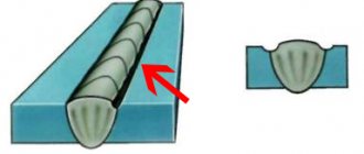
If the material requires deep heating, then the electrode is directed towards itself. Following him in the direction of the welder is the working area. The resulting slag covers the fusion site.
If the work does not involve strong heating, then the electrode is moved away from you. The welding zone “crawls” behind it. The depth of heating with this type of weld is minimal. The direction is clear.
Types of welding seams
The location of the welding workpieces determines the type of connection.
- Butt . The end parts of the elements that are in the same plane are connected. There are several options for performing the operation: with or without a bevel, with flanging.
- Overlap . Most often used for pipes and profile connections. The parts are arranged parallel and one of them is partially immersed in the other.
- Corner . Welds are laid on both sides. Can be done without bevels or with only one.
- Tavrovoe . Visually, the junction resembles the letter “T”. Sometimes two workpieces are positioned at an acute angle. In any case, the end of one of them is connected to the side of the other. The welding seam is laid on both sides with or without bevels.
Trajectory of movement
The trajectory of the electrode has a particular influence on the seam. In any case, it has an oscillatory character. Otherwise, it will not be possible to sew the two surfaces together.
Oscillations can be similar to zigzags with different steps between the sharp corners of the trajectory. They can be smooth, resembling movement in an offset figure eight. The path can be similar to a herringbone or a capital letter Z with monograms at the top and bottom.
An ideal seam has a constant height, width, uniform appearance without defects in the form of craters, undercuts, pores, or lack of penetration. The name of the possible flaws speaks for itself. Having mastered your skills well, you can successfully apply any seam and weld a variety of metal parts.
Types of welding
The quality of welds largely depends on the equipment used. Main welding types:
- Manual arc . This method can be used to fasten parts made of metals of any thickness.
- Automatic . The equipment required is a transformer, rectifier or inverter.
- In an inert gas . The connection is very strong. Inert gases protect metal parts from oxidation. The advantages include the absence of slag and waste, as well as a neat appearance.
- Gas . The seam is carried out under the influence of the combustion temperature of the gas from the burner.
- Using a soldering iron.
The type of welding is selected based on the requirements for the weld.
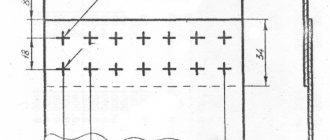
Standards and the concept of leg
The weld begins to form in the working area when the metals are molten, and is finally formed after solidification.
The existing classification groups seams according to various criteria: the type of connection of parts, the resulting shape of the seam, its length, the number of layers, orientation in space.
The types of possible welded joints are shown in the standard for manual and arc welding GOST 5264. Connections made by arc welding in a shielding gas atmosphere are standardized by the GOST 14771 document.
GOSTs have a designation for each welded joint, as well as a table containing the main characteristics, in particular the values of the leg of the weld.
It’s quite easy to understand what a leg is by looking at the drawing of the parts being connected. This is the side of a speculative isosceles triangle of maximum dimensions that will fit in the cross section of the seam. A correctly calculated leg value guarantees the strength of the connection.
For parts of uneven thickness, the cross-sectional area of the part in its thinnest part is taken as a basis. You should not try to unduly increase the leg. This can lead to deformation of the welded structure. In addition, the consumption of materials will increase.
Checking leg dimensions is carried out using universal reference templates presented in specialized literature.
Manual arc welding
Manual arc welding is welding with a metal electrode coated with a special coating, to which welding current is supplied to form and maintain an electric arc. The arc is ignited when the end of the electrode briefly touches the workpiece being welded.
Manual arc welding process diagram:
| 1) Crystallized weld metal. | |
| 2) Hardened slag. | |
| 3) Weld pool. | |
| 4) Gas atmosphere of the arc. | |
| 5) Electrode rod. | |
| 6) Electrode coating. | |
| 7) Drops of molten electrode metal. | |
| 8) Depth of penetration. | |
| 9) Product to be welded. | |
| 10) Welding direction. |
Let us consider in more detail all the processes occurring during the welding process:
- Under the action of an electric arc, the metal rod of the electrode and the metal of the welded product melts. The electrode metal in the form of separate drops covered with slag passes into the weld pool, where it mixes with the base metal, and the molten slag floats to the surface.
- Slag, covering drops of molten electrode metal and the surface of the weld pool, prevents their interaction with air, and also helps clean the molten metal from impurities.
- When the electrode coating melts, a gas atmosphere is formed around the arc and above the weld pool, displacing air from the welding zone to prevent its interaction with the molten metal.
- The final step is that the metal of the weld pool crystallizes and a seam is formed.
Types of connections
Depending on the relative position of the parts, welding joints occur:
- end-to-end;
- overlap;
- in an angular way;
- in a tee way.
When butt welding, the ends of two parts located in the same plane are welded. The joint can be made with a flange, without a bevel, or with a bevel. The shape of the bevel may resemble the letters X, K, V.
In some cases, welding is done with an overlap, then one part is partially mounted on another, located parallel. The combined part is an overlap. Welding is done without bevel on both sides.
Often there is a need to make a welded corner. This connection is referred to as the corner type. It is always done on both sides and may not have bevels or have a bevel on one edge.
If the welded parts result in the letter T, then a T-joint has been made. Sometimes parts welded with a T-seam form an acute angle.
In any case, one part is welded to the side of the other. Welding is carried out on both sides without a bevel or with bevels on each side.
Classification of welds
There are different types of welds and seams. The developed classification takes into account the technological features of the seams, their spatial position, dimensions and other factors. This paragraph discusses in detail all types of welds and structural connections.
According to the location of the welded elements
Depending on the relative position of the welded elements, the following types of welded joints are distinguished:
| Butt joints (seam types C1 - C48) . With this processing method, the parts are located in the same plane. In this case, welding can be carried out both on weight and on a lining. The butt weld is suitable for joining pipes and metal sheets. The resulting connections have the lowest stress concentration and ensure equal strength of the connection with the base material. |
| Lap joints (types of welds H1 - H2) are made with parallel arrangement of parts in space. In this case, one part partially overlaps another. The overlap connection is applicable when welding metal sheets with a thickness of no more than 12 mm. If during operation of the unit, fracture loads are possible, then it is better to avoid using this connection method. |
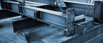
| With T-joints (types of seams T1 - T9) , made with fillet welds, the end of one part is located perpendicular to the main surface of the second part. Such a connection is widely in demand when constructing load-bearing structures, since it is considered the most durable - capable of withstanding increased loads. |
| Corner joints (weld types U1 - U10) are made by placing parts at an angle (usually at a right angle) and then welding them at the junction of the edges. According to the manufacturing technology, such connections can be one-sided or two-sided, and the welds used at their base are fillet welds. Corner joints are most often used when connecting parts of various containers and reservoirs. |
| With end connections, the workpieces are placed parallel, one on top of the other, and welded together at the ends. In this way, parts of any thickness can be connected with minimal deformation. |
| Fused welds are a special type that is used in T-joints, lap joints and is limited to parts up to 10 mm thick. Such seams are made by completely melting the top sheet and partially melting the bottom sheet of the workpiece. A type of penetration welds are cork penetration welds. They are formed as a result of melting of the upper thinner sheet. Such electric rivets can be installed either without a hole in the sheet being welded or along a hole. |
Welding seams by length
The length of the seams can be continuous or intermittent:
| 1) Continuous one-sided seam. | |
| 2) Intermittent one-sided seam. | |
| 3) Continuous double-sided seams. | |
| 4) Double-sided chain stitches. | |
| 5) Double-sided checkerboard seams. |
Intermittent welds are suitable for non-stressed (and/or leaking) joints and can be arranged in a chain or staggered pattern. The length of the connected sections ( l ) is usually 50 - 150 mm. The gap between the seams ( t ), called the step, is usually made 1.5 - 2.5 times the length of the welding zone l .
Welds by number of layers
Depending on the number of layers, welding can be single-layer or multi-layer, and based on the number of passes – single-pass or multi-pass. It is advisable to use a multilayer weld when processing thick metal. Also, using the multi-layer method on thinner workpieces, it is possible to reduce the heat-affected zone.
Structure and terminology of a multilayer weld:
| Weld layer - weld metal consisting of one, two or more beads that are placed at the same level of the cross-section of the weld. | |
| Pass - a single movement of a heat source in one direction during welding or surfacing. | |
| Bead is a portion of the weld metal that has been deposited in one pass. |
When performing a multi-pass weld, it should be taken into account that each new layer should be applied quickly, before the previous one has cooled down (the time spent on removing slag must also be taken into account).
The positive effect of multi-pass technology includes the fact that when a subsequent seam is applied, annealing occurs in the previous one. Annealing is a type of heat treatment that involves heating to a certain temperature, holding for a certain time at this temperature and then, usually slowly, cooling to room temperature.
Seams according to position in space
According to their position in space, seams are divided into:
| a) Lower . This position of the workpieces is the most convenient for the welder. | |
| b) Horizontal . This arrangement of the seam line, as in all other cases, leads to metal dripping during operation. You can combat this by increasing the speed of movement of the electrode, or regularly interrupting the arc, allowing the metal to cool. | |
| c) Vertical . In this case, there is also the problem of molten metal (drops) draining. And if welding is carried out from top to bottom, then these droplets will begin to quickly solidify, forming a kind of barrier. Therefore, welding with the vertical method should be carried out from the bottom up. | |
| d ) Ceiling (top) . Such seams require a certain skill from the welder, since during the work he will have to take an unnatural posture. Welding of the ceiling joint is carried out in short arc mode with electrodes no thicker than 4 mm. The width of the seam should be less than the thickness of the electrode. Welding should be done in the “toward” direction. |
Weld seams by appearance
Based on the appearance of the outer surface, welds are divided into convex (reinforced), normal and concave.
Shape of butt welds:
| a ) Convex weld | |
| b ) Normal seam | |
| c ) Concave seam |
Typically, when manual welding, convex (reinforced) seams are used, which work better under static (constant) loads. However, when choosing a more reliable connection, you should understand that they are uneconomical in terms of electrode and energy consumption.
If the welded product is expected to be subject to dynamic loads during operation, then when joining workpieces it is better to use a normal (flat) or concave seam. The advantage of this approach is that there is no large difference between the surfaces of the welded products and the seam.
Shape and extent
The shape of the seam can be convex, even (flat). Sometimes it becomes necessary to make a concave shape. Convex joints are designed for increased load.
The concave areas of the alloys withstand dynamic loads well. Flat seams, which are made most often, are characterized by versatility.
The length of the seams is continuous, without intervals between the fused joints. Sometimes interrupted stitches are sufficient.
An interesting industrial variation of the intermittent seam is the joint formed by resistance seam welding. It is done on special equipment equipped with rotating disk electrodes.
They are often called rollers, and this type of welding is called roller welding. Continuous connections can also be made using such equipment. The resulting seam is very strong and absolutely airtight. The method is used on an industrial scale for the manufacture of pipes, containers, and sealed modules.
Electrode movement and current intensity
Two significant factors have a great influence on the quality of the weld – the current strength and the speed of movement of the electrode. The supply of high current allows you to heat the metal to a greater depth. In turn, this allows the welder to move the electrode faster while maintaining good quality work. It is the optimal ratio of current strength and consumable feed speed that ensures a high-quality welded joint.
Correspondence table for current, electrode, metal thickness
| Current strength, A | Electrode diameter, mm | Metal thickness, mm |
| 35-50 | 1,6 | 1-2 |
| 45-80 | 2 | 2-3 |
| 65-100 | 2,5 | 3-4 |
| 85-150 | 3 | 4-5 |
| 125-200 | 4 | 5-6 |
When choosing the speed to move the arc, you should take into account its power. Excessively fast feeding with a relatively low power of the electric arc does not allow the metal to be sufficiently heated to its entire depth. It turns out that the seam simply “lies” on the joint surface, barely catching the edges. And, conversely, with slow movement in combination with a sufficiently powerful electric discharge, there is a high probability of overheating and deformation of the metal along the welding line. If the workpieces have thin walls, they can burn through.
Layers and spatial arrangement
A metal seam can consist of a bead made in one pass. In this case it is called single-layer. If the parts being welded are thick, several passes are performed, as a result of which beads are sequentially formed one on top of the other. This welding joint is called multilayer.
Considering the variety of production situations in which welding occurs, it is clear that the seams are oriented differently in each specific case. There are lower, upper (ceiling) seams, vertical and horizontal.
Vertical seams are usually welded from bottom to top. The trajectory of moving the electrode along a crescent, herringbone or zigzag is used. It is more convenient for novice welders to move the crescent.
When welding horizontally, several passes are made from the lower edge of the parts being joined to the upper edge.
In the lower position, butt welding is carried out or by any angular method. A good result is obtained by welding at an angle of 45 °, “in a boat”, which can be symmetrical or asymmetrical. When welding in hard-to-reach places, it is better to use an asymmetrical “boat”.
The most difficult thing to do is weld in the ceiling position. This requires experience. The problem is that the melt tries to drain out of the work area. To prevent this from happening, welding is carried out with a short arc, the current strength is reduced by 15-20% compared to normal values.
If the thickness of the metal at the welding site exceeds 8 mm, then several passes must be performed. The diameter of the first pass should be 4 mm, subsequent ones - 5 mm.
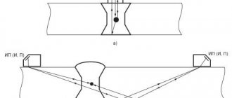
Depending on the orientation of the seam, select the appropriate position of the electrode . To make horizontal, vertical, ceiling connections, and weld non-rotating pipe joints, the electrode is directed at an angle forward.
When welding corner and butt joints, the electrode is directed at an angle backwards. Hard-to-reach places are welded with an electrode at a right angle.
Welded joint, seam shape and image in the drawing
Having understood the process of manual arc welding, during which a seam is formed, let’s move on to considering the main zones of the weld and its shapes.
The welded joint includes four zones of metal:
| 1 ) The weld zone is an alloy formed by the molten base and weld metals. | |
| 2 ) In the fusion zone , where the heating is below the melting temperature, there are partially melted metal grains at the boundary of the base metal and the weld metal. The metal grains here are separated by liquid layers associated with the liquid metal of the weld pool. | |
| 3 ) The heat-affected zone is a section of the base metal that has not undergone melting. The structure and properties of this zone change as a result of heating during welding. | |
| 4 ) Part of the base metal adjacent to the heat-affected zone. |
There are front and back sides of the seam. The front side in a one-sided seam is taken to be the one from which welding is performed. In a double-sided weld with an asymmetrical bevel - the side from which the main seam is welded. In a double-sided seam with a symmetrical bevel - either side.
Weld sides
According to the shape of the outer surface, welds are:
| 1 — 2 — 3 - convex seam. When it cools, shrinkage (indicated by a dotted line) occurs calmly. The dotted line of the weld is shorter than the original one, so no tensile stress occurs in the weld. | |
| 1 — 4 — 3 - concave seam. The shrinkage of the seam proceeds with the lengthening of the contour curve, so local rupture and crack may occur. |
Basic geometric parameters of a butt weld according to GOST 2601 – 84:
| S is the thickness of the metal being welded. | |
| e is the width of the weld. | |
| g - convexity of the butt weld - the greatest height (depth) between the surface of the weld and the level of the surface of the welded parts. | |
| h - penetration depth (depth of penetration) - the greatest depth of melting of the base metal. | |
| t is the thickness of the seam (g + h). | |
| b - gap. |
Basic geometric parameters of fillet weld according to GOST 2601 – 84:
| K - fillet weld leg - the shortest distance from the surface of one of the parts being welded to the boundary of the fillet weld on the surface of the second part being welded. | |
| g - convexity of the seam. | |
| Hp - design height of a fillet weld - the length of a perpendicular line drawn from the point of greatest penetration at the junction of the welded parts to the hypotenuse of the largest right-angled triangle inscribed in the outer part of the fillet weld. | |
| a is the fillet weld thickness (g + p). |
Visible welds in the drawing are depicted by the main line, and invisible ones - by dashed lines:
Seam designation in the drawing
Weld joint processing
When welding, slag is formed. If slag inclusions get into the weld, its quality deteriorates. All slag deposits must be cleaned off.
If welding is performed in several passes, then the seams are cleaned after each welding stage. In this case, any methods are used. First, the welded parts are hammered and cleaned with a stiff brush.
Then a rough cleaning is carried out. Small parts are cleaned with special knives or grinding wheels. Large blanks are cleaned on machines. At the final stage, the welded joint is polished.
Often a fiber wheel of a grinding machine is used for this. There are other ways to polish welded joints.
Welding is constantly evolving. New materials are appearing and technology is improving. It is necessary to follow the news in welding to learn a lot of new and interesting things.
Elimination and prevention of welding defects
When eliminating a welding defect in the form of lack of fusion, the root at the defect site is cleaned and welding is carried out again. During installations of important structures, the defective area is cut down or cut out and then welded again.
The following methods will help prevent lack of penetration in welds:
Edge cutting
A method where edges are pre-cut at a certain angle. In this case, free contact of the electrode to the root of the seam and dullness are left. In the right place, dirt, oxide, rust are cleaned and the surface is degreased. The prepared parts are placed evenly in one plane, leaving a gap between the edges.
You can read more about preparing metal for welding here.
Heat supply
A method when the welding speed is set so that the metal of the edges has time to melt, since during the rapid movement of the electrode the heat is only enough for seam formation. When welding parts repeatedly, remove the slag after all passes, as it will interfere with the melting of the previous seam.
Alternately following welding modes
Setting a medium or high current value that will correspond to the thickness and metal of the prepared parts. To avoid lack of fusion at the ends of the seam and when replacing the electrode, inverters regulate the function of increasing the voltage for a short time. To prevent non-fusion on an old welding device without adjusting the arc parameters, select the time to detect minimal fluctuations in the mains voltage.
Correct electrode position
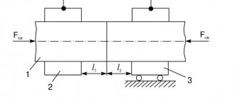
When welding, the arc is drawn along the axis of the joint to heat both edges equally. Failure to do this will prevent the edge from fusing to the seam. The electrode is moved forward at an angle of 5-20 degrees. When welding fillet welds with a boat, the electrode is held at the same distance from the surface of the parts. When the workpieces are connected into an asymmetrical “boat”, the electrode is placed at an angle of 30 degrees to one of the planes of the parts.
Weld parts at high current with direct or reverse polarity. When welding with reverse polarity current, a short arc is used, which can cause undercuts. And due to the large diameter of the electrode, slag particles can get into the edge gap.
Refractory oxides
These are components formed when alloys and alloy steel are heated. If the elements are welded incorrectly, the slag remains inside the seam, forming defects in the form of lack of fusion. To prevent this, oxygen is needed to form oxides. When using a consumable electrode, it is worth choosing a device with a coating that matches the type of metal.
Now overcoming local lack of penetration should not frighten novice welders. The main thing is not to create reasons conducive to its formation. If it could not be avoided, the defect can be eliminated, but it is better to try to prevent the occurrence of non-fusion.