What is a laboratory autotransformer (LATR)
Very often among electricians and electronics engineers the abbreviation LATR . Remember, we once looked at the power supply and even made it ourselves. The power supply gave us a constant voltage from zero to some final value, which, of course, depended on the steepness of the power supply. Agree, a very convenient thing. But there is one drawback - it only gives us constant voltage .
But, since there is a power supply for constant voltage, then there must be a power supply for alternating voltage . And such a power supply is called a laboratory autotransformer , or LATR . What is this thing and what is it eaten with?
LATR is the same transformer. It converts alternating voltage of one magnitude into alternating voltage of another magnitude . But the trick is that we can change the voltage at the LATR output if necessary.
Main areas of application of LATR
All similar types of autotransformers have a fairly narrow application due to their design features, namely:
- In the laboratories of various research institutes and enterprises to carry out test work in relation to equipment operating on AC, as well as as a U stabilizer to reduce the mains voltage (at the input).
- For commissioning and debugging of industrial devices, electronic and highly sensitive equipment and most devices that require a reduced U level for operation.
- As a battery charger.
- In housing and communal services.
- In educational institutions for laboratory work.
Types of LATRs
Single-phase
This type of LATR produces single-phase alternating regulated voltage. It is very often used by radio amateurs, as it allows you to select any low-voltage alternating voltage.
Three-phase
This type of LATR is used in industrial electronics. A three-phase voltage is supplied to its input, and at the output we get the same three phases, but with a smaller amplitude. This LATR allows you to change the voltage amplitude of all three phases simultaneously . Roughly speaking, these are three single-phase LATRs, which are located in the same housing and which change the voltage equally.
Description of the work of LATRA RESANTA
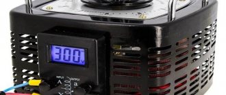
Let's look at a single-phase LATR manufactured in Latvia RESANTA (read in Russian) brand TDGC2-0.5 kVA.
From above our LATR looks like this:
We see a regulator with which we can set the voltage we need.
On the front side we see some kind of alternating voltage voltmeter. We apply voltage from the 220 V network to the terminals on the left, and from the terminals on the right - the voltage that we currently require.
Operating modes
- In autotransformer modes (a), it is possible to transfer rated power from the HV winding to the LV winding or vice versa. In both modes, the series and common windings are loaded with typical power, which is acceptable.
- In transformer modes, it is possible to transfer power from the LV winding to the MV or HV winding, and the LV winding can be loaded to no more than Stype. In these modes, the AT is underloaded, which is acceptable, but uneconomical.
- In combined mode (b), it is possible to transfer power of no more than S type from the LV network to the HV network and at the same time (Snom Stype) by autotransformer from the MV network to the HV network. This mode is acceptable and economical, because the load of the common winding can, in the limit, be equal to 0, and through the AT the total is transmitted Snom.
Also read: What is a transformer
Choosing the optimal operating mode is important for three-phase devices. They are used for continuous parameter adjustment with low losses. This component provides users with the best possible adjustment accuracy with minimal losses and therefore reduced heat generation. For three-phase current, this effect is achieved using mechanical connections of three control transformers. The sliding current collectors are designed in such a way as to ensure reliable output contact and, when triggered, simultaneous cleaning of the contact track. Carbon brushes are used that can rotate or move back and forth.
A variable autotransformer has multiple primary windings to create a secondary voltage that is regulated in the range of a few volts to fractions of volts per revolution. This is achieved by placing a carbon brush or slider in contact with one or more turns of the primary winding. Since the turns of the primary coil are evenly distributed along its length, the output value is proportional to the angular rotation of the brush.
How LATR works in practice
Let's conduct experiments with a 95 Watt 220 Volt incandescent light bulb. To do this, connect it to the output terminals on the right.
I wonder at what voltage the light bulb filament will start to glow? Let's find out! We turn the regulator until we notice a faint glow of the light bulb.
We look at the regulator scale. 35 Volts!
Did you know that in the USA the mains voltage is 110 Volts? I wonder how our light bulb would glow then? We set it to 110 Volts.
It glows, as they say, at full incandescence.
Now compare how it glows at 220 V
There is no point in increasing the voltage further. The light bulb may burn out.
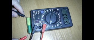
If you want to set the voltage with great accuracy, then, of course, you can’t do without a multimeter. To do this, set the multimeter knob to the AC voltage measuring position.
We cling and measure the alternating voltage. At the same time, we adjust it using the LATR regulator. Exactly 110 Volts!
Load power (from 0 to ? VA)
Obviously, you can reduce the load indefinitely, and even not connect it at all (load 0), the current will not increase. But what is the maximum load that can be connected to the LATR if the maximum permissible current and output voltage are known? Let's carry out the calculation using the data from the previous example (maximum LATR current is 2 A, required output voltage is 110 Volts). From the formula above, we derive the load power:
It turns out that a load greater than 220 VA cannot be connected to the SUNTEK 500 VA (2 A) LATR with an output voltage of 110 Volts.
Safety precautions when working with LATR
I would also like to add a few words about safety precautions. There are LATRs without galvanic isolation . This means that the phase wire from the network goes directly to the output of such a LATR. The LATR circuit without galvanic isolation looks like this:
In this case, a network voltage of 220 Volts may appear at the output terminal of the LATR with a probability of 50/50. It all depends on how you plug the LATR mains plug into a 220 Volt socket.
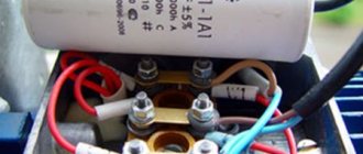
If you look closely at the circuit diagram on the front panel of the LATR Resanta, you can see that the “X” and “x” terminals (the two bottom ones) are connected to each other by a conductor.
That is, if there is a phase on the “X” terminal, then there will also be a phase on the “x” terminal! You won’t measure the phase in the socket every time to insert the plug correctly, will you? Therefore, BE extremely CAREFUL! Try not to touch the LATR output terminals with your bare hands!
In principle, I touched it and nothing like that happened to me. The problem turned out to be that I have a wooden floor, which is almost a dielectric. I measured the voltage between me and the phase - about 40 Volts came out. That's why I didn't feel these 40 Volts. If I grabbed the battery with one hand or stood with my bare feet on the ground, and with the other hand grabbed the output “x” of the LATR, then I would be shaken very, very strongly, since all the full 220 Volts would pass through me.
Important selection options
First of all, you need to determine what the autotransformer will be used for. For example, to test the performance of power equipment at a factory, you will need one model; to provide power supply when repairing car radios, you will need a completely different one. To make it easier to formulate requirements for the device, consider the following parameters:
Power. You can select an LATR with a power from 0.45 to 10 W (and even more), but first you need to calculate the load of all connected electrical consumers. Their total power should not exceed the power of the autotransformer.
Voltage adjustment range. It depends on how the device operates - to lower or increase voltage parameters. Most models are of the step-down type, especially single-phase; their operating range can be from 0 to 250 V or from 160 to 220 V. Depending on what voltage value is needed to operate the equipment, choose an LATR with the appropriate range. Three-phase models have a wider range: the lower limit can be at a level of 200-220 V. A laboratory autotransformer with a wide operating range is not always needed, for example, if the voltage in the network drops to 180 V (not higher or lower), then you can buy transformer with adjustment within 180-220 V.
Supply voltage. If you plan to connect the device to a single-phase network, then you need to buy a 220 V model, if to a three-phase network - 380 V (in this case, the adjustment range for such a model can go far beyond the nominal values of a three-phase network, for example, it can be from 0 to 430 IN).
So, have you already decided to buy a laboratory autotransformer? With this device, you yourself can adjust the voltage in the network and set the values that are necessary for a specific type of energy consumer. You can quickly select and order suitable equipment on our website. Don't delay your purchase - take control of your stress!
Source
Isolation transformer and LATR
There are also safer types of LATRs. They include an isolating transformer . The diagram of such a LATR looks something like this:
As we can see, the phase wire is isolated from the output terminals of such a LATR, thanks to a transformer, the operating principle of which you can read in this article. In this case we may be shaken if we set a high voltage at the output of the LATR using a twister and grab two output wires of the LATR at once. That is, there is a typical galvanic isolation .
Wire calculation
It is not advisable to use an autotransformer for large transformations for the following reasons:
- There is a high risk of receiving currents close to a short circuit. This is compensated by special electronic circuits or additional resistance. For small loads it is more profitable to use an electronic LATR.
- The advantages over transformers are lost: high efficiency, saving on conductor and steel, small dimensions and weight, cost.
We are determining within what limits the LATR will operate. We select 220 V for the network supply. We select 127, 180 and 250 V as secondary voltages. We limit the power to 300 W. You can choose your own values and make similar calculations using the example of this article.
The winding is calculated based on the larger current. The highest current will be when converting a voltage of 220 to 127 V. The autotransformer in this case is a step-down one, and circuit 1 is suitable for it. Based on the provided circuit, we calculate the maximum current I passing in the winding of both circuits:
I = I2 – I1 = P / U2 – P / U1 = 300 / 127 – 300 / 220 = 1 A
- where I, I2, I3 are currents in the corresponding sections of the circuit, A;
- P – power, W;
- U1, U2 – primary and secondary circuit voltages, V.
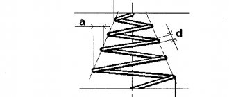
The wire diameter is calculated using the formula:
d = 0.8 * √I = 1 mm.
From Table 1, select the wire type and cross-section. We make the choice taking into account the calculated current and the average current density for transformers - 2 A/mm².
The LATR transformation coefficient n is calculated using the formula:
n = U1 / U2 = 220 / 127 = 1.73
For further calculation, we calculate the design power Pр:
Pр = P * k * (1 – 1/n) = 300 * 1.2 * (1 – 1/1.73) = 151.92 W
where k is a coefficient that takes into account the efficiency of the autotransformer.
To determine the number of turns per 1 volt, it is necessary to calculate the cross-sectional area of the core S and determine the type of magnetic circuit:
S = √ Pр = √ 151.92 = 12.325 cm²
W0 = m / S = 35 / 12.325 = 2.839
- where W0 is the number of turns per 1 volt;
- m – 50 for rod and 35 for toroidal magnetic cores.
If the steel is not of very high quality, it is worth increasing the W0 value by 20-30%. Also, when calculating turns, their number should be increased by 5-10% to avoid voltage sag. We calculate the number of turns for selected voltages 127, 180, 220 and 250 V:
w = W0 * U
We get 360, 511, 624 and 710 turns.
To calculate the length of the wire, we wrap one turn around the magnetic circuit and measure its length. Then we multiply by the maximum number of turns and add 25-30 centimeters for each terminal to the terminal.