Documentation for welded structures
A special type of assembly models are welded structures, the creation process of which consists of “cutting”, “welding”, “processing” and “modelling”. For any of the states, specific views can be created in the drawing:
- Assembly state views allow you to see what the model looks like without welded joints or the required cutting;
- types of preparation represent a model with an already specified cutting of connecting seams;
- types of welding show the future model with welded joints;
- types of processing determine the model with preparation of joints, with ready-made joints and processing after welding.
When designing drawings, only the assembly state can be applied. When the structure goes into any of the other states, an appropriate message about this should be provided.
What are the types of welds?
Modern types of welding open up a huge number of possibilities for the master, allowing him to translate any ideas into reality. But in order to put any welding technology into practice, you need to understand the designation of welding and learn how to draw up drawings.
Depending on the technology, the welding symbol in the drawings is as follows:
- E - electric arc;
- Kt - contact;
- G - gas;
- Z - performed in a protective gas environment.
The drawings contain all the information that a craftsman may need in the process of welding metal structures, so a prerequisite for every professional welder is the ability to read and draw up welding drawings.
Types of welding joints and symbols
To ensure high-quality connection of individual elements when creating metal structures, it is necessary to have a detailed description of each joint. To do this, design documentation consisting of drawings is carried out, in which all symbols of welds must comply with GOSTs.
Depending on the methods of joining the elements welded to each other, several types of connections are distinguished. The names, features and designations of welding seams in the drawings can be found in the table below.
| Types of seams | Characteristics | Welding seam on the drawing |
| Butt | Parts located in the same plane are welded at adjacent ends. In order for the joints to be smooth and strong, it is necessary to process the butt edges before joining. | WITH |
| Angular | The parts are connected along ends inclined to one another, the angle between which should be more than 30° | U |
| Tortsevoy | The ends of the elements are connected so that the side surfaces touch each other | WITH |
| Lap | The planes of the elements are superimposed on one another. Used in cases where the accuracy of the fit is not critical | N |
| Tavrovy | The end of the part is welded to the surface of the structure at an angle or vertically | T |
There are also special types of seams not provided for by GOST, which are indicated in the diagrams by the symbol “O”.
Graphic work 14. assembly drawing of a welded joint
Goal of the work:
learn how to make an assembly drawing of a permanent welded joint, draw up a specification for a permanent joint.
THEORETICAL MATERIAL
Drawings of a welded product are performed as an assembly drawing. When making a drawing of a welded assembly unit, working drawings of the parts included in the assembly unit are first made.
Each such part must be assigned a designation and name, for example, plate, strip, gusset, rib, bushing, ring, cylinder, plate, etc. When making working drawings of a part, it is necessary to determine the type of edges for welding and indicate on the drawings the necessary data for the manufacture of parts. The specification indicates the format of the sheets on which the sketches were made.
In the case where the welded product is simple, its parts can be manufactured directly according to the assembly drawing. In this case, all the dimensions necessary for the manufacture of parts are indicated on the assembly drawing. In the specification, in the “Format” column, enter the warhead symbol (without a drawing), provide the designation and name of the parts, their quantity.
A welded product made of a homogeneous material is depicted in sections and sections in one of three ways:
1) boundary details are hatched as one whole (in one direction) with contour lines drawn between them;
2) boundary details are hatched without indicating the boundaries between them, like a monolithic body;
3) border details are hatched in different directions in accordance with the general rules of shading.
Figure 85 shows an example of a drawing of a welded product “Support”.
Exercise:
make an assembly drawing of the welded joint. Material of all parts: St 5 GOST 380–94
Procedure for completing the task
1. Select a task option (Fig. 86-88);
2. Find out what parts the assembly unit consists of;
3. Give the name of each part;
4. Complete an assembly drawing of the welded unit;
5. When making a drawing in A4 format, place the specification above the main inscription.
6. Fill in the title block of the drawing.
Figure 85 – Assembly drawing of a welded joint
Figure 86 – Assignment for options 1-6
Figure 87 – Assignment for options 7-12
Figure 88 – Assignment for options 13-15
Graphic work 15. execution of an electrical circuit drawing
Goal of the work:
learn how to draw an electrical circuit and list elements for a circuit diagram.
THEORETICAL MATERIAL
Scheme -
This is a graphic design document that shows the component parts of the product and the connections between them in the form of conventional images or symbols.
Schemes are used when studying the principle of operation of machines, mechanisms, instruments, apparatus, during their adjustment and repair, installation of pipelines and electrical networks, to clarify the connection between the individual components of a product without specifying the features of their design.
Depending on the nature of the elements and communication lines that make up the device, circuits are divided into types, each of which is often designated by a letter: kinematic (K), hydraulic (H), pneumatic (P), electrical (E), optical (O) and etc.
Depending on the main purpose, circuits are divided into types, each of which is usually designated by a number: 1 - structural; 2 - functional; 3 - fundamental; 4 — connections (installation); 5 - connections; b - general; 7 - location, etc.:
1. Schematic elements
- a component of a circuit that performs a specific function (purpose) in a product, which cannot be divided into parts that have an independent functional purpose (for example, a pump, coupling, capacitor, resistor, etc.).
2. Device
- a set of elements representing one structure (for example, a ratchet mechanism, a printed circuit board, a cabinet).
3. Functional group
- a set of elements that perform a specific function in a product and are not combined into one structure.
4. Functional part
— element, equipment or functional group.
5. Interconnection line
- a line segment on a diagram showing the connection between the functional parts of the product.
When executing the diagram, the scale is not respected. The actual spatial arrangement of the component parts of the product may not be taken into account in the diagram or taken into account approximately.
Symbols for elements of general use are established by GOST 2.721-74.
Elements that make up a separate device may be highlighted on the diagrams with dash-and-dotted thin lines indicating this device.
Table 11 - Graphic symbols of general use for use in electrical, hydraulic, thematic and combined circuits (excerpt from GOST 2.721-74)
| Name | Designation |
| Flow of electromagnetic energy, electrical signal in one direction | |
| Fluid flow in one direction | |
| Gas (air) flow in one direction | |
| Straight one-way traffic | |
| One-way rotational movement | |
| Screw movement | |
| Mechanical communication lines in hydraulic and pneumatic circuits | |
| Mechanical communication lines in electrical circuits | |
| Regulation. General designation | |
| Examples of designation of adjustable elements: - belt transmission with changing gear ratio - adjustable resistor |
Each element shown in the diagram conventionally must have its own designation: a serial number or an alphanumeric positional designation. For each type of diagram, rules for applying such designations are established.
On hydraulic, pneumatic and electrical circuits, designations are entered into a list of elements, drawn up in the form of a table, filled in from top to bottom (Fig. 89).
Electrical circuits have classifications, terms and definitions that are established by GOST 2.701-84. They are carried out in accordance with GOST 2.702-75 - “Electrical circuits. General requirements for implementation."
| In Fig. 90 shows a schematic diagram of the electrical power supply to the electromagnetic clutch. Electrical communication lines (wires) must consist of horizontal and vertical sections, usually made with a thickness of 0.3 ... 0.4 mm. The gap between any two parallel lines must be at least 2mm. Conventional graphic symbols of elements are drawn on the diagram with lines of 1.8 ... 1.4 mm. Each element included in the product and shown in the diagram has an alphanumeric positional designation, composed of a letter designation and a serial number placed after the letter designation. The standards establish alphanumeric designations for the most common elements. For example, resistor - R; capacitor - C;
| ||||||||||||||||||||||||||||
Necessity of notation
Modern metal structures consist of many elements of different shapes and sizes. In order for them to meet all the requirements of GOSTs, they must be created according to previously developed design documentation.
The designation of welds in the drawings allows you to find out a complete list of their technical characteristics:
- the type of materials needed to create high-quality joints;
- geometric dimensions of seams and optimal tolerance parameters;
- welding technologies;
- size and shape of the deposit;
- tightness of joints and strength properties;
- conditions and sequence of the welding process and other features.
Not only in the manufacture of metal products is it necessary to mark welding seams; checking finished structures for the strength and integrity of joints also requires drawings. The monitoring employees compare the geometric parameters of each connection with the indicators from the design documentation.
Using CAD
CAD for marking welds
By automating routine processes, CAD allows the designer to significantly reduce project development time. They make it possible to simulate various situations, instantly carry out complex calculations, and select ready-made engineering solutions from built-in libraries.
A big advantage of CAD is the automation of documentation development in accordance with the conditions of the ESKD. For example, in Compass, searching and placing weld symbols on drawings takes a matter of seconds.
The ability to use conventional markings is necessary for a qualified specialist in the field of construction or production. Correctly drawn up design documentation is a necessary condition for the successful implementation of the entire technological chain of manufacturing products using welding work.
Video on the topic: Designation of seams in the drawing
Publications on the topic
What is a weld leg
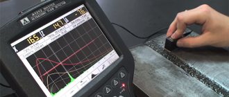
Features, advantages and disadvantages of ultrasonic flaw detection of welds
Features of welding thin metal with an inverter
How welding seams are shown on the drawings
The requirements for the development of working documentation and the symbols of welds on the drawings are regulated by the unified system of design documentation (ESKD).
Regardless of the welding method, two main types of lines are used to indicate welds in the drawing:
- solid - for external visible joints;
- dashed (dotted) - for invisible connections.
In the photo below you can see which line represents a visible weld in the drawing and an invisible one.
In both cases, there must be an extension line with an arrow indicating the location of the seam. If the arrow points to a visible joint, then the symbol is placed above it, when an invisible one is placed below it.
When a joint is made by several passes superimposed on each other, it is called a multi-pass weld; the number of passes is indicated in the drawing when it is designated.
All connecting joints can be made:
- one-sided . Formed when welding parts on only one side of the surface, they are represented by the symbols SS;
- - sided When creating this type of joint, the heating source alternately moves along the upper and lower surfaces and the root of the butt weld is located inside the section. The symbol BS represents such welding in the drawing.
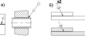
To ensure optimal depth when welding using the fusion method, it is necessary to prepare the edges. In this case, the shape, opening angle, bluntness, gap width and other parameters depend on the welding technology and the thickness of the material. The most common edge sections are shown in the picture below.
According to the nature of execution, welding joints are divided into spot, intermittent and continuous. The designation on the drawing of an intermittent weld is a solid line for visible joints and a dashed line for invisible ones. Intermittent joints are created in a checkerboard pattern or chain.
For any welding technology, spot welding is indicated in the drawing by the “+” sign, which consists of solid lines. Single invisible points are not displayed on design diagrams.
Designation of joints according to the nature of execution
The tables below show how welds are designated in the drawings depending on their nature.
Butt joint table
| The nature of the joints | No bevels | Bevel on one edge | Bevel on two edges | Two symmetrical bevels on both edges |
| Unilateral | ||||
| Bilateral | ||||
| One-way connections using a gasket |
Fillet Weld Table
| Character of the seam | No bevel |
| Unilateral | |
| Bilateral | |
| End-to-end one-sided | |
| End-to-end double-sided |
Table of Welds on a T-Type Drawing
| Nature of the connection | Without bevel |
| Double-sided regular | |
| Double-sided staggered |
Table of lap joints
| Nature of the butt joint | Without bevel |
| What does a double-sided joint look like? | |
| Intermittent Weld Symbol |
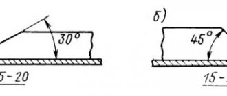
According to generally established international standards, seams also differ from each other in relation to spatial position:
- vertical and horizontal;
- welded in the lower position and ceiling.
Considering the position of the joint, there are also different ways to remove the edges. If you carefully clean and prepare the edges before the welding process, the connecting joint will have a number of advantages:
- economy . The amount of metal used for welding is reduced to a minimum;
- efficiency . Much faster welding in one pass;
- strength . The strength characteristics of the resulting welded joint are in no way inferior to the strength characteristics of the base metal.
In order to obtain a result of exceptional quality during the welding process, it is imperative to indicate in the technical documentation the type of welding joint and the type of edge to be removed.
Pereosnastka.ru
Weld seams
Category:
Metal welding
Weld seams
A weld is a section of a welded joint formed as a result of crystallization of molten metal. A weld is a part of a welded joint that differs in structure from the structure of the base metal.
Based on the type of connection and cross-sectional shape, welds are divided into butt and corner welds. Butt welds are used to make butt and, much less frequently, corner and T-joints. Fillet welds are used in corner, T and lap joints.
A butt weld is characterized by the width of the seam (e) and the depth of penetration (ft). The characteristics of a fillet weld are the width of the seam (e), the thickness of the seam (a) and the leg of the seam (K).
Depth of penetration of a butt weld (ft) is the greatest depth of fusion of the base metal in the cross section of the weld.
Fillet weld thickness (a) is the greatest distance from the surface of the fillet weld to the point of maximum penetration of the base metal.
Fillet weld leg (K) is the shortest distance from the surface of one of the parts being welded to the boundary of the fillet weld on the surface of the second part being welded. With a symmetrical fillet weld, any of the equal legs is taken as the design leg; with an asymmetrical weld, the smaller one is taken.
Weld convexity (g)—The convexity of the weld is determined by the distance between the plane passing through the visible boundary lines of the weld and the base metal and the surface of the weld, measured at the point of greatest convexity.
Rice. 1. Butt and fillet welds: e - weld width; h—penetration depth; g - convexity (reinforcement) of the seam; a is the thickness of the seam; c - seam leg
The seams of welded joints can be classified according to various criteria.
According to the shape of the outer surface. Welds can be convex, flat, or concave. Butt seams are made convex (with reinforcement) and flat. Concavity of butt welds is unacceptable; this is a serious welding defect.
Corner seams are made convex, flat, concave. Concavity (A) of fillet welds during welding in all spatial positions is allowed no more than 3 mm.
Convexity (reinforcement) of welds is allowed no more than 2 mm when welding in the lower position and no more than 3 mm when welding in other positions. It is allowed to increase the reinforcement of welds made in vertical, horizontal and ceiling positions by 1 mm with a base metal thickness of up to 26 mm and by 2 mm with a base metal thickness of over 26 mm.
Welded joints with convex (butt and fillet) welds work better under static loads. But seams with excessive reinforcement are undesirable for two reasons: a) increased consumption of electrodes and electrical energy;
b) stress concentration at the points of intersection of the weld surface with the base metal.
Welded joints with flat (butt and fillet) and concave (fillet) welds work better under variable and dynamic loads.
According to the welding position. In accordance with GOST 11969-79 (ST SEV 2856-81) (“Fusion welding. Basic provisions and their designations”), welds are classified depending on the welding positions. The welding position is determined by the angle of inclination of the longitudinal axis of the seam (a) and the angle of rotation of the transverse axis of the seam ((3) relative to their zero positions.
Rice. 2. Classification of seams according to the shape of the outer surface: a - butt convex; b - butt flat; c - butt concave; g - angular convex; d - angular flat and concave
Rice. 3. Position of the seams in space: a - lower; b - vertical; c - horizontal; g - ceiling
The following welding positions and their designations are established: lower - H, boat - L, horizontal - G, semi-horizontal - Pg; vertical - B, semi-vertical - Pv; ceiling - IT, semi-ceiling - Pp.
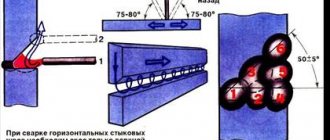
Welding in the lower position is most convenient and easy to master. In factory conditions, using various devices, it is possible to almost completely weld structures in the lower position. Welding of seams in vertical, horizontal and ceiling positions is carried out in construction and installation production.
By length. There are continuous and intermittent welds. Continuous weld - a weld without gaps along its length. Continuous seams are conventionally divided by length into short (up to 300 mm), medium (up to 1000 mm) and long (over 1000 mm).
Intermittent weld - a weld with intervals along its length. The distance from the beginning of one seam section to the beginning of the next section is called the seam pitch (t). Intermittent seams can be chain or checkerboard.
Chain interrupted seam is a double-sided interrupted seam in which the gaps are located on both sides of the wall, one against the other.
A checkered intermittent seam is a double-sided intermittent seam in which the gaps on one side of the wall are located opposite the welded sections of the seam on the other side.
In relation to the direction of the acting force. There are flank (side), frontal, oblique, and combined welds.
The flank seam is located parallel to the direction of the acting force.
The front seam is located perpendicular (normal) to the direction of the acting force.
Rice. 3. Intermittent welds: a - chain; b - chess; c - step of intermittent seam; g - length of the seam section
Rice. 4. Types of welds according to the method of filling the seam section: a - single-layer; b - multilayer; c - multilayer multipass
The oblique shoyo is located at an angle to the direction of the acting force. The combined seam is a combination of flank and oblique, flank and frontal.
According to the method of filling the seam section. There are single-layer (single-pass), multi-layer, and multi-layer multi-pass welds (Fig. 4).
In a multilayer seam, the number of layers is equal to the number of passes. If in a multi-layer seam some layers are made in several passes, then such a seam is called multi-layer multi-pass.
In butt welded joints, single-layer and multi-layer seams are mainly used. In corner, T and overlap joints, single-layer and multi-layer multi-pass welds are more often used.
According to the conditions and place of execution. There are factory welds and assembly welds. Factory welds, as a rule, are made indoors (shop, workshop or assembly workpiece area), i.e. in the most favorable production conditions for welding. An assembly seam is a weld performed during the installation of structures or structures. Assembly seams are often made in conditions unfavorable for welding (at high elevations, in different spatial welding positions, in the open air, in winter and summer).
Read more:
Types of welded joints
Related articles:
pereosnastka.ru
Types of seams according to the shape of the outer surface
The shape of the connecting joint directly affects its physical and mechanical characteristics, as well as the consumption of electrodes. When seams are convex, they almost always require additional processing using abrasive wheels or a cutter.
The table below shows the types of convex joints and how a welded joint is conventionally designated in design drawings.
| Connection types | What does the joint look like? | Image | Characteristics |
| Normal | _____ | They are economical to create and have high endurance under constant loads. | |
| Concave | Effective under dynamic loads, simple and economical to implement | ||
| Convex | If there are bulges at the joints, then they require much more consumables and are not economical |
Types of edge removal
Edges can be made from different sides and at different angles depending on the thickness of the metal used for welding. The following varieties exist:
- perpendicular at an angle of 90°: the metal should not exceed 8 mm in thickness for double-sided welding, up to 3 mm for one-sided welding, 4-8 mm for steel sheets;
- V-shaped with a one-sided bevel with a range of sheet thicknesses ranging from 4-26 mm;
- X-shaped with the creation of a double-sided bevel, while the thickness of the metal should be 12-40 mm;
- at an acute angle, which decreases from 60° to 45° with a thickness of 20 mm or more.
In order for the seams to be strong and of high quality, the distance between the edges should be 4 millimeters.
Auxiliary signs
The welding designation in the drawing will be incomplete and incomprehensible without auxiliary symbols. The table below shows auxiliary signs, indicating what each of them means when applied to the diagram.
Using auxiliary signs, specialists when drawing up diagrams of metal structures indicate the following information:
- The need to eliminate the convexity at the joint that arose during welding work.
- The need to ensure a smooth transition to the main surface. This can be done by mechanical or manual processing of all existing irregularities.
- The welding line of the elements must remain open.
- The contour of the welding joint must be closed.
- First, it is necessary to install the prepared parts and only then begin the welding process.
- It is necessary to make a point or intermittent seam, its location should be chain.
- It is necessary to create a connecting joint in a checkerboard pattern.
Each additional designation of a weld is regulated by GOST and indicates clarifications that should be additionally carried out at the joint.
Notes on notation
In order to see how a weld is indicated on the drawing and correctly read all the technical information, you should remember some nuances:
- the side from which the one-sided joint is welded is the front surface;
- in a double-sided connection, the edges of which are asymmetrical relative to one another, the front side is considered to be the one with which the main seam is made;
- the front surface of a double-sided joint, in which the edges are prepared symmetrically, can be protruded by either side.
All additional symbols and signs are applied to the diagrams with thin solid lines. When creating drawings, you should pay attention to the fact that all signs must have the same height as the numbers.
The table below provides some examples of how additional symbols are used in drawings.
| Name | What does the joint look like? | Image on drawings |
| Single-sided flat connection, V-shaped edge preparation | ||
| The seam is convex on both sides, the edges are separated in the form of a V symbol | ||
| Concave corner joint | ||
| Butt joint on one side, the edges are separated in a V-shape with a flat underweld seam | ||
| The butt weld is one-sided, the edges are separated using the V method with a large bluntness and an underweld seam | ||
| Single-sided flat joint with V-shaped edge separation. The gain was removed using additional processing | ||
| Corner connection with a smooth transition to the base metal from the seam itself |
Rules for applying and deciphering symbols
In the drawings, a visible welded joint is indicated by a solid line, an invisible one – by dashes. To describe a seam, an arrow with a shelf is used, pointing to the line of the joint. Symbols for visible connections are located above the shelf; when describing invisible connections, they are located below the shelf. The inscription on both sides of the arrow indicates double-sided processing.
The welding symbol in the drawing is divided into 9 blocks:
Weld designation structure
- Block 1 – Auxiliary sign (when making a closed or assembly seam).
- Block 2 – Standard for welding method.
- Block 3 – Marking the type of seam.
- Block 4 – Hyphen (division into subcategories).
- Block 5 – Letter designation of the type of welding (automatic - A, electroslag - Ш, melting electrode in a gas cloud - IP, etc.). May not be specified.
- Block 6 – Icon the length of the seam leg in mm.
- Block 7 – Additional parameters (checkerboard or chain arrangement, step interval, etc.).
- Block 8 – Auxiliary symbols for indicating processing.
- Block 9 – The value of the cleanliness of the joint surface (if machining is necessary).
Illustration of connections for different types of welding
Depending on the type of welding technology used, the types of welds and joints are depicted differently; their designations in the drawings are indicated in the table.
| Welding method | How to show welding on a drawing |
| To manufacture the structure, welding is used using an automatic machine. It is carried out under a layer of flux; preliminary welding of the joint is not required. No pads or pillows are used in the work | A |
| Submerged arc welding using an automatic setup using a special flux base pad | Af |
| The connection of parts must take place in an inert gas environment. The work is carried out with a tungsten refractory electrode. The technology does not require the use of additional filler material | IN |
| The elements are connected with a tungsten electrode using inert gas welding using filler metal | INp |
| In an inert gas environment, parts are welded to each other using a consumable electrode | IP |
| Welding work is carried out in a protective gas environment, carbon dioxide is used for this | UP |
| You need to use gas welding technology | G |
| Connecting elements using the electric arc method | E |
| Work must be carried out using protective gas | Z |
Features of decoding technical abbreviations
Each welder must be able to decipher all the images and symbols indicated on the design documentation, for example, what line represents the weld in the drawing or what the resistance welding designation looks like in the drawing.
There are two effective ways to master the skills of reading technical diagrams:
- carefully study all current interstate standards, according to the requirements of which design and technical documentation is drawn up. In addition to GOSTs, you will also need to read special literature, which contains designations of welding seams in the drawings and their interpretation;
- Using the example of finished drawings, study all the information presented. This will allow you to master the material with optimal intensity and speed and deepen your knowledge gradually.
Since the information laid out in the standards is structured according to the general requirements for a certain type of work, professional specialists consider the second option to be more convenient and accessible. It is much easier to find exactly the information that a welder will need in his work.
Designation of welded seams.
The symbol on the drawing of a weld is:
- T-weld. Of all the possible connection options, this one is considered the most rigid and is not used if the design provides for at least some elasticity, since this type of seam is the joining of two elements at an angle of ninety degrees.
- C stands for butt weld. If those structural elements that need to be connected are on the same plane, then this welding method is often used (butt to butt). It is considered the most difficult, so as a rule, only professional welders can do it.
- U-this means fillet weld in drawings. The end parts of two workpieces located at an angle of ninety degrees are melted, resulting in a fairly strong connection.
- H stands for lap seam. It is definitely inferior to the T-bar because it is less rigid. As a rule, it is used if the workpieces for welding are in different planes and they are parallel to each other.
You can clearly see what the seams of the presented types look like in this figure:
All other welding seam options are shown as “O” - there is a special type . They are not included in the main standards, but are also used in work.
A qualified welder simply needs to know all the designations of welding seams and their abbreviations.
Designations are taken from GOST, mainly 5264 or 16037, or GOST 14771-76
They all echo each other.
For example, the symbol for an RDS weld according to GOST 5264 is:
To carry out work in an inert environment according to GOST 14771 it will be:
By analogy, the same with GOST 16037
Rules for applying designations and features of their decoding
It has already been mentioned above how the designation of welded joints of different types should be carried out. The joint line is indicated by a line with a directed arrow, above or below which inscriptions are applied.
There are certain rules according to which all technical inscriptions must be applied. Marking of welds consists of 9 interconnected blocks. The photo below shows the structure of the markings.
The photo shows how a welded joint is indicated in the drawing using the example of a double-sided assembly butt weld performed by manual arc welding:
- The first column shows an auxiliary sign. This is the contour of a closed seam that determines the installation conditions applied to the element.
- The second block contains the code of the interstate standard, in accordance with which work on welding metal structures must be carried out.
- The third column is the marking (designation) of the weld in the drawing.
- Next is a hyphen, which in a subcategory separates all subsequent positions.
- The letters in the fifth block indicate the technology used to perform welding work. This position is not mandatory.
- The sixth column contains the size of the corner leg, its value is indicated in millimeters.
- Seventh block: additional designation - interrupted weld, pitch interval, chain or staggered arrangement, etc.
- The eighth block displays auxiliary signs indicating the type of processing.
- The last ninth column is indicators of the cleanliness of the surface of the butt joint. Indicated in cases where mechanical processing of the product is necessary after the welding process.
This is the standard designation of welds in drawings; examples of the designation of some already completed connections are given below.
Example 1
The weld symbol shown in the drawing is deciphered as follows:
- the sign indicates that directly at the installation site, after adjusting the elements, they should be connected;
- GOST 5264-80 is the number of the regulatory document, in this case it indicates that the joint was made using electric arc welding;
- C13 - means that in the butt joint there is a curved chamfer on one bevel;
- the sign indicates that internal thermal stress (effort) has been removed from both sides of the seam;
- Rz20 is an indicator of the surface cleanliness of the front side, Rz80 is the back side.
Example 2
Shown here is a double-sided (U2) fillet weld made by automatic arc welding (A) along a closed line under submerged arc (GOST 11533-75) without beveled edges.
Example 3
A joint is created on the back side.
The connection is made using electric arc welding in accordance with GOST 5264-80. The seam is one-sided with a folded edge, the contour is open.
Example 4
Welding joint at an angle
- the contour of the joining of elements is continuous, made in the shape of a ring;
- welding was carried out in a gas environment, GOST 17771-76;
- T-joint (TJ), each side was processed without cutting the edges;
- carbon monoxide (CO) of gaseous consistency was used as a gaseous medium, the electrode was molten;
- 6 mm is the length of the butt joint leg;
- in a checkerboard pattern (Z), a continuous welded section 50 mm long and in increments of 100 millimeters is periodically created.
Example 5
To make the seam, semi-automatic arc welding is used; the drawing indicates that the seam is one-sided (H1), created by an overlapping consumable electrode without bevel of the edges in a protective gas environment. The seam is circular (), made along a closed line, 5 mm (Δ5) is the length of the leg.
If the drawing contains several identical connecting joints, then only one of them is marked with a symbol. For the remaining seams, in places where there should be a designation, only their serial numbers are indicated. In this case, the number of identical connections is indicated on the leader line, as shown in the example below.
Butt joints are considered identical in cases where:
- the types of joints and dimensions of the elements are the same when comparing their cross-section;
- The same requirements apply to all connections.
When a control category or control complex is established for a welding joint, a symbol should be applied only under the leader line.
svarnoy.info
In accordance with GOST 2.312-72, the seams of welded joints in the drawings are indicated by solid (visible) and dashed (invisible) lines. A visible single weld point (regardless of the welding method) is conventionally represented by the “+” sign (see Fig. 1), invisible single points are not depicted. From the image of a seam or a single point, draw a leader line with a one-way arrow and a horizontal shelf line. A conventional image of the seam is drawn on the shelf of a leader line drawn from the image of the seam on the front side (Fig. 1, b), and under the shelf of the leader line drawn from the image of the seam on the back side (Fig. 1, c).
Rice. 1. Conventional images of visible and invisible seams of welded joints: a - visible electric rivet, b - visible one-sided butt, c - invisible one-sided butt; 1—symbol of a seam according to GOST
Table No. 1.
Auxiliary symbols for designating welds
| No. | Auxiliary sign | Meaning of the auxiliary sign | Location of the auxiliary symbol relative to the leader line flange | |
| From the front side | On the reverse side | |||
| 1 | Remove seam reinforcement | |||
| 2 | Process sagging and unevenness of the seam with a smooth transition to the base metal | |||
| 3 | The seam should be made during installation of the product, i.e. when installing it according to the installation drawing at the place of use | |||
| 4 | The seam is intermittent or point with a chain arrangement. The angle of the line is 60° | |||
| 5 | The seam is interrupted or dotted with a checkerboard arrangement | |||
| 6 | Seam along a closed line. Sign diameter - 3...5 mm | |||
| 7 | Seam along an open line. The sign is used if the location of the seam is clear from the drawing | |||
Notes:
1. 3a the front side of the one-sided seam of the welded joint is the one with which the welding is performed.
2. The front side of a double-sided seam of a welded joint with asymmetrically prepared edges is taken to be the one with which the main seam is welded.
3. Any side can be taken as the front side of a double-sided seam of a welded joint with symmetrically prepared edges.
In Fig. Figure 2 shows the structure of the seam symbol. Auxiliary symbols for designating welds are given in table. 1, and GOST standards for the main types and structural elements of welded joints are in Table. 2. In the structure of the conventional image of the seam, only auxiliary signs 3 and 6 can be used. The designation of the standard can be included in the technical conditions in the drawing. Manual arc welding does not have a letter designation. The welding method may not be specified. Examples of symbols for seams of welded joints are taken from GOST 2.312-72 (Appendix 1) and are presented in Table. 3.
If there are identical seams in one of the images in the drawing, the designation and serial number of the seam are applied (on the extension line), and leader lines with shelves are drawn from the images of the remaining identical seams, above (below) which the serial number of the seam is placed, for example No. 1 (Fig. .3). On a leader line that has a shelf with a printed designation, it is allowed to indicate the number of identical seams.
Rice. 2. Structure of the standard seam symbol
2 - standard designation, 1 - auxiliary signs,
3 - alphanumeric designation of the seam according to the standard for types and structural elements of seams of welded joints,
4—hyphen sign,
5 - symbol of the welding method (A - automatic, P - mechanized submerged arc, P-3 - mechanized with a consumable electrode in shielding gases; Ш - electroslag, etc.),
6 - sign and size of the leg according to the standard for the types and structural elements of welded joints,
7 - other characteristics of the seam (length of the welded section, step size, sizes of individual points, etc.),
8 - auxiliary signs (see Table 1, serial numbers 1, 2, 4, 5 and 7), 9 - weld surface roughness.
Fig.3. Designation on the drawing of identical seams (the number 12 indicates the number of identical seams)
Table No. 2.
GOST standards for the main types and structural elements of welded joints
| GOST | Welding method | Connection type | Seam symbol | |
| 5264—80 | Manual arc | Butt | C...C27; C39; C40 | |
| Angular | U1…U10 | |||
| Tavrovoe | T1...T9 | |||
| Overlapping | HI; H2 | |||
| 11534—75 | The same (at acute and obtuse angles) | Angular | U1...U8 | |
| Tavrovoe | T1...T8 | |||
| 14771—76 | Arc in shielding gases | Butt | C1...C28 | |
| Angular | U1…U10 | |||
| Tavrovoe | T1...T9 | |||
| Overlapping | H1...H2 | |||
| 23518—79 | The same (at acute and obtuse angles) | Angular | U1…U10 | |
| Tavrovoe | T1...T9 | |||
| 8713—79 | Automatic submerged | Butt | Cl...C34 | |
| Angular | U1...U4 | |||
| Tavrovoe | Tl...T13 | |||
| Overlapping | |H1...H6 | |||
| 11533—75 | The same (at acute and obtuse angles) | Angular | U1...U6 | |
| Tavrovoe | Tl...T9 | |||
| 14806—80 | Arc aluminum and aluminum alloys (thickness of elements - 0.8... ...60 mm) | Butt | C1…C27 | |
| Angular | U1…U 14 | |||
| Tavrovoe | T1…T12 | |||
| Overlapping | H1, H5 | |||
| 16098-80 | Arc and electroslag double-layer corrosion-resistant steel | Butt | Cl...C22 | |
| Angular | U1…U11 | |||
| Tavrovoe | T1…T6 | |||
| 15164-78 | Electroslag | Butt | S1…SZ | |
| Angular | U1…U4 | |||
| Tavrovoe | T1…TZ | |||
| 14776-79 | Arc electric rivets under submerged arc, in carbon dioxide and argon | Overlapping | H1…H6 | |
Table No. 3
Examples of symbols for standard seams
| Cross-sectional shape | Symbol for the seam shown in the drawing | |
| from the front side | on the back side | |
| A butt joint seam with a curved bevel of one edge, double-sided, performed by manual arc welding during installation of the product. Reinforcement has been removed on both sides. The roughness of the seam surfaces on the front side is 5, on the back side 20. | ||
| Corner weld, connection without beveled edges, double-sided, performed by automatic submerged arc welding with manual welding along a closed line | ||
| An overlap joint seam without beveled edges, one-sided, performed by mechanized arc welding in shielding gases with a consumable electrode. Seam - along an open line; seam leg - 5 mm | ||
Non-standard seams
Connections in which the dimensions of structural elements are not clearly indicated are called non-standard. The designation of non-standard welds in the drawings must be carried out indicating the dimensions of all constituent elements.
In the photo below you can see in detail how the drawing shows welding performed with non-standard seams.
During welding, due to uneven heating of butt joints, residual shortening deformation is formed, which causes the appearance of residual stresses.
Various factors influence the distribution of such stresses: welding mode, geometric parameters of the connecting seam and many others. If we take into account the thickness of the elements being connected, then a volumetric or plane state of stress may arise in this regard.
The boundaries of a non-standard joint are depicted by main solid lines, and the structural elements located within the seam are depicted by thin solid lines.
Arrangement of symbols in drawings
If we consider the complete conventional image of a connecting joint, then the additional and main signs contained in it constitute only part of the designation. In addition to them, the image includes other elements:
- line with a direction arrow;
- double leader, which consists of two (dashed and solid) lines parallel to each other;
- a fork that complements the leader line, behind which additional information necessary for high-quality connection is placed.
The dotted line can be either below or above the solid line. The mark indicating the seam, depending on which direction the arrow is directed, is applied on a solid or dotted line:
- when there is a symbol on a solid line, it means the arrow is pointing to the front side;
- the sign is marked on the dotted line - the arrow is directed towards the opposite side of the joint.
If we are talking about joints with an asymmetrical groove, then the arrow should be directed to the side with the processed edge.
Additional data for butt joints
Additional information includes the following features of connecting seams:
- circular joint . In this variety, the circle is a designating symbol;
- assembly joint . Here the checkbox acts as a symbol.
If in the image of the welding joint you additionally need to indicate:
- in accordance with ISO 4063 welding technology code;
- in accordance with ISO 10042 and ISO 5817, the quality level extended to the joint;
- according to ISO 6947 welding position;
- in accordance with ISO 544, 2560, 3581 welding material used
then such information must be placed behind a fork added to a solid leader line.
Possible simplifications
Design documentation must be completed even when manufacturing the simplest welded metal structure. If all connections are made according to a single standard, then welding symbols are also applied on the drawings accordingly and all graphic information is described in an explanatory note, which is an unchanged part of the documentation.
According to the special instructions of GOST 2.312-72, other simplifications are considered acceptable:
- when all the joints present in the drawing are on the same surface and are similar in type, then they are allowed not to be assigned a serial number. For images of such seams, leader lines are drawn in which there are no flanges;
- in the case when it is necessary to produce a symmetrical part, the presence of symbols on only one of its sides is not considered a violation. This is allowed when the diagram has an axis of symmetry that performs the function of dividing the part;
- if two or more identical elements welded in a similar way are contained in one drawing, then only one of the component parts is allowed to be highlighted with a leader line. Here the designated element must have its own serial individual number;
- in some cases, it is permissible in the explanatory note compiled for the drawing diagrams to depict the extension line with a special instruction. This is possible in situations where the location of the seam is determined with extreme accuracy. The note also indicates the operational characteristics (quality and technical) of the butt joint.
Designation of welds using simplifications allows you to:
- do not overload the drawing with many symbols;
- significantly simplify the drawing itself. If the welding points are obvious, then some simplifications can make the drawing more understandable and accessible. Almost always, in the absence of CAD, it was possible to significantly increase the efficiency of the designer’s work due to simplifications;
- reduce the number of weld markings several times by assigning numbers to all identical joints while knowing with accuracy the quantities of each type of connection.
It should also be noted that the more technically complex the drawing is and the more simplifications it contains, the more difficult it will be for the welder to read welding drawings. You also need to know that there are certain restrictions on the use of simplifications and there are a number of cases when they are unacceptable when creating complex design diagrams.
Example of reading a part drawing
The main inscription indicates that this technical drawing shows a threaded connection, in particular a bolted connection. It also contains the document code and product index. The scale of the drawing is made in full size, namely 1:1.
The main view is presented with a superimposed cross-section of the fastened parts. The connection is shown in two views. A bolt with a metric thread and a height of 120 mm and a 30 mm diameter is presented separately. The nut is also shown in the top view. But the dimensions of the washer according to this drawing are unclear.
Create drawings using CAD
Almost all drawings, according to which various metal structures are subsequently manufactured using welding technologies, are made using special software (CAD). Automation of the process of creating technical diagrams allows developers to significantly save time on drawing up project documentation.
Thanks to CAD, designers quickly and with maximum accuracy apply all welding seams on the drawings; their designation is also carried out by appropriate software systems that are capable of not only modeling the most complex metal products, but almost instantly carrying out the most complex calculations of welding joints through the selection of ready-made engineering solutions in specialized built-in libraries.
Currently, designers are offered a large number of different products, of which the following software systems are the most effective and in demand:
- Kompas;
- AutoCAD;
- SolidWorks.
For example, in a matter of seconds, Compass finds any necessary welding drawings, and their interpretation is immediately displayed on the monitor without the need to waste time searching for additional sources.
Undoubtedly, a professional designer must be able to manually carry out technical diagrams and, even more so, know how welding is indicated on the drawing. But at the same time, work productivity will be much higher if specialized programs are used in the process of preparing documentation.
Using software packages, you can develop not only units and assemblies of welded structures, but also calculate the maximum permissible loads during their operation. In turn, this allows specialists, even at the project development stage, to apply the right decisions regarding the design features of metal products, while eliminating the formation of inaccuracies due to inaccurate selection of welding technologies and, in particular, types of connecting joints.
All modern automated programs offered to design engineers are developed with maximum compliance with the requirements established by technical regulations and legal documents.
The ability to use the designation of seams of welded joints in drawings and, in particular, to create diagrams in an automated mode using CAD allows you to correctly and accurately draw up documentation and provide conditions for the successful manufacture of metal products through welding work.
Requirements for symbols
Regardless of what type of welds are used in the manufacture of metal products, the designation on the drawings must be carried out in accordance with a single set of requirements. The information reflected in the diagrams and explanatory notes must be provided in specially designed forms:
- technical description of the joints connecting individual elements into a single structure;
- table of welds in the drawing, an example of filling it out in different versions is presented above. The welding itself differs in certain features when drawing up drawings. It should be carried out only in the form established by the current requirements.
Only a drawing developed in accordance with all regulations and standards can act as a guarantee that the specialist will not have any problems during the welding process and will be able to accurately and promptly carry out tasks of any complexity. If there are errors in the drawing that violate the requirements, then the regulatory authorities will not be able to approve it.
An equally important stage of the welding process in comparison with the work is the preparation of technical documentation, since the determining factor of what the welding joint should be is the drawing.
If we talk about the symbols of connecting joints, then regardless of the technology of the welding process, there are also specific requirements. Along with ensuring the clarity of the drawing, the symbols used also greatly simplify the work of the welder.
Specific features are provided for each individual designation. Considering that the welder, when manufacturing products, is guided by the drawing presented to him, even the slightest inaccuracies in it can lead to the fact that the finished structure will not meet the technical characteristics put forward for it.
Every specialist working with welding must know what is indicated in the weld symbol on the drawing and be able to quickly and accurately read any information. Without such skills, it is almost impossible to determine what characteristics a welding joint should have and what type of seam to use in specific cases.
The main document that sets out all the requirements regarding how welding is shown in the drawing by any method is the unified state standard. At the same time, not only the specialists developing technical drawings must unquestioningly master all existing requirements, but also those who will directly weld metal products in the future according to the drafted projects. Such knowledge is a guarantee that the project will be implemented efficiently.
Symbols in the drawing
Just as welding is indicated on the drawings, additional auxiliary marks (signs) must also be shown.
With their help, professionals creating welding patterns can:
- Indicate with the help of signs that it is necessary to make a smooth transition to the main surface. This can be achieved by correcting unevenness using manual or mechanical processing;
- Highlight the point that when welding elements, the line must remain open
- Show that it is necessary to make a seam in such a way that it is chain;
- Focus on the fact that the contour of the joining seam must be closed
- Show that the connecting joint should be made in a checkerboard pattern
It is important to know that all additional signs are regulated in GOST and they specify what additionally will need to be done at the welding junction.