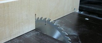
A circular saw carriage is a necessary tool in the arsenal of a carpenter. The purchased option is often overpriced and may not meet the individual requirements of the client. This article suggests studying the features of such an important device as a carriage and trying to make it at home.
A tabletop is required to use the carriage
What is a circular saw carriage and why is it needed?
The carriage, or guide bar, is an auxiliary tool when working with a saw. It comes in different sizes and is required to cut wooden blanks from small frames to large panels, for example, furniture. It provides the most accurate cutting, reducing the need for further adjustments to the product.
It is sometimes easier to make such a useful accessory as a carriage for a circular saw with your own hands than to buy a ready-made kit. In this case, you can accurately adjust all sizes.
Characteristics of carriages
When purchasing or creating a homemade carriage, the following indicators are taken into account:
- Parameters of wooden parts.
- The functionality of the saw and its capabilities: power, productivity and others.
- Frequency of operation.
In order for the device to serve for a long time and efficiently, it is necessary to control:
- Length and width of the cut.
- Direction and ease of movement of the tool.
- The density of the product used by the master.
- Sequence of work, safety precautions.
- General purpose of the saw.
Guide bar - what is it?
Basically, a guide bar is a rail that helps allow a handheld table saw to slide back and forth while keeping the tool from straying from the cutting line. But a properly made guide will not only ensure an even cut, but will also help reduce the number of chips in the area of contact between the material and the saw.
Self-made guides have different designs and are made from the most unusual materials. It could be:
- Guide made of plywood.
- Rail-type miter box made of aluminum corner.
- Profile tire (made of aluminum).
- A ruler that is made on the basis of rules.
- External type of carriage on bearings.
The remote carriage and miter box are the most difficult to implement. A tire made of plywood or one made from a profile will be much simpler in design features, but this does not mean at all that the cut made with its help will not be as high quality. The difference between these varieties is largely in how convenient it is to use one or another device.
Advantages and disadvantages of a homemade circular saw carriage
When creating a carriage for a circular saw, you can:
- Achieve optimal sizes.
- Change the standard appearance, for example, make a radius carriage for curved shapes.
- Choose suitable materials: aluminum, wood, profiles, etc.
- Save money - use the tools you have on hand.
However, if you make the guide yourself, a number of difficulties will arise. In particular, it is necessary to have appropriate knowledge about the process and acquire specific tools for the job, which a non-professional carpenter may not have.
Carriages are divided into manual and stationary, amateur and professional
How many types of tires does a circular car have?
The circular saw guide not only serves as a safety element, it allows you to increase productivity. Devices of different designs have been developed, they are:
- bilateral;
- one-sided;
- symmetrical;
- asymmetrical.
A universal device is used to process a workpiece of non-standard shape. This guide can be used with a circular saw or a hand saw.
Tires for circular saws
Specialized tires are used when performing professional tasks.
When crossbars are cut at an angle, a textolite or plywood restriction made of bars is installed. Before installing supports, check:
- reliability of clamps;
- tire surfaces for deformation;
- for compliance of the workpiece materials with the guide.
Thrust slats are made of metal or wood
It is important that they are stable under mechanical stress. Did not change their shapes and sizes
Products are used for production from:
- profile;
- rail;
- corners;
- bars.
The structure is attached to the base:
- self-tapping screws;
- screws;
- bolts.
Ruler
There is another stubborn tool - a ruler.
It's quite simple to make from a strip of plywood. The width of the fragment is taken 20 cm more from the working area. And the base is fixed with fastening hardware. Before work you need to check with test cuts:
- tool behavior;
- vibration;
- the level of physical effort required to perform the operation.
Reliable, safe execution of actions depends on the fastenings:
- clamps;
- clamps;
- movable carriage;
- retainers.
These elements fix the workpiece in the required position. The installed limiter prevents the sharp cutting part from deviating from the perpendicular arrangement of the wood fibers.
Design Features
Immediately before work, you should figure out what parts the slide consists of and how they are connected to each other. The structure will be discussed using the example of a tenoning slide for a milling machine.
Dimensions, weight and general appearance
The size of the carriage is individual and largely depends on the specific saw, its cutting depth, as well as the purpose of use. Thus, the unit together with the tenoning guide can reach 800 kg. To avoid inaccuracies, experts advise making a design drawing.
Tool protection design
The tool protection is a separate structure, which contains a pipe and bracket, guide lines and a slider.
Advice! It is advisable to use a handwheel to control the movement of the protective ruler. Screws help install such a shield and fix it at the top and bottom.
List and location of controls
The compact control panel has:
- Button to turn on and off the drive.
- Mounting handles.
- Handle that clamps the spindle head.
- Spindle stop.
- Flywheel.
- Keys for fixing the ruler bracket.
- Colored light bulbs giving a signal.
Arrangement of components
The main part of the structure is a cast-iron frame, a cast-iron table with rigid ribs and a moving carriage. The guide, in turn, consists of a plate, a clamp and a ruler, bearings and travel restrictions.
Component mechanisms and units of the unit
Composition of the spindle head:
- Cast iron body.
- Bearings.
- Spindle.
- Removable frame.
Drive parts in the equipment:
- Motor with 2 speeds.
- Spindle head.
- Connecting mechanism.
- The tile located under the motor.
- Poly V-belt transmission.
Kinetic scheme
When independently manufacturing a guide structure, the master needs to study the kinetic and electrical structure. The kinetic diagram describes the entire operation of the device - its parts and the relationships between them, the principle and sequence of actions.
The structure is manufactured in accordance with the kinetic and electrical circuit
Electrical diagram
An electrical diagram is a graphic document that identifies all the elements of a specific piece of equipment. In general, using conventional images, this diagram demonstrates the process of converting electrical energy, in particular, to activate the saw carriage.
Electrical equipment
The circular saw carriage is powered by an electric motor with 2 speeds, which is connected to the spindle through a belt. Due to this design, the latter is capable of accelerating in 2.3 seconds.
Important! The engine almost always has a protective mechanism to prevent overheating.
Recommendations for simplifying the assembly process
To regulate belt tension, the electric motor must be installed so that it can be moved. The easiest way to achieve this is by creating larger slots than required for the motor mounting bolts. In this case, the expansion of the holes should be carried out in the direction of belt tension.
If you completely follow the drawing, you will need to make a more complex belt tensioning mechanism. The process will be carried out by pulling up the platform with the electric motor using studs and fixing it with locking bolts in the desired position (in the drawing these structural elements are indicated by the number 10).
The entire design and assembly process can be greatly simplified if you make a circular saw from a circular saw. In this case, there is no need to install a number of parts (motor, disk, shaft, belt, starter). But the capabilities of the created model will be limited by the power of the tool used.
In any case, a homemade circular machine must be grounded. It is also additionally recommended to install a residual current device or differential circuit breaker in the panel. These measures will protect against electric shock if the machine body is energized, for example, due to breakdown of wire insulation. It is better to select components for the electrical part of a circular saw so that they are suitable for repair and easy to maintain. Free access to equipment components will help you easily replace failed parts.
Step-by-step instruction
Below is a detailed process for making a simple saw carriage.
Marking guides
The grooves for the runner must be clearly parallel to the circular disk. Therefore, the necessary marks are placed on the tabletop with a pencil and a ruler and the central axis is drawn. Accurate marking is the key to a quality tool.
Additionally! If there are no backlashes, the ruler should be pressed against the disk itself.
Milling grooves for runners
When the main line is ready, grooves are made on both sides of it at equal distances using a milling machine. Metal profiles (U-shaped) can be inserted into the grooves so that the grooves last longer and the slides move easily.
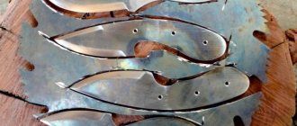
Making runners
The slats are cut from wood. Preference is given to hardwoods - maple, oak and others. The slides should fit well into the grooves, but not too tightly, otherwise the carriage will not be able to move. If this step is completed correctly, the base of the sled will easily install on the workbench.
To cut at a non-standard angle, you will need to additionally make a combined square
Mounting the carriage base onto the skids
The runners are glued, then a plywood sheet is placed on them. While the glue is active, a weighting agent is placed on the plywood, or it is fixed with any clamp. It is advisable to sand the plywood first.
Advice! To prevent the glue from leaking and getting onto the surrounding surface, the edges of the guide rails can be limited with tape.
Marking the corners of the carriage
The carriage is installed in the grooves, and the master saws through its front part. From this section 2 angles of 45 degrees are measured. After which the corners are cut off on both sides.
Correction of carriage angles
It is necessary to secure the structure and make several preparations to evaluate the functionality of the carriage. If the angles in the sawn slats are not correct, the circular slide is corrected: its borders are trimmed. Then you need to make a test cut again.
This procedure is carried out until the desired effect appears in the size of the cut, the vibration level and the need to apply effort in the process.
Simple and reliable guide for a hand-held circular saw
Hello, dear readers and DIYers! Surely many of you have to work with a hand-held circular saw, and one of the most basic tasks is to make an even cut at a right angle to the part. This problem is solved in many different ways.
In this article, the author of the YouTube channel “JSK-koubou” will tell you how to make a device with which you can quickly and accurately cut both wide boards and small-sized timber.
This homemade product is very easy to make and does not require complex tools, milling, turning, or expensive materials.
Materials. — Pine timber 15X30 mm — Screws, washers, wing nut — PVA glue or titebond II.
Tools used by the author. — Japanese saw — Hand-held circular saw — Cordless nailer — Screwdriver, wood drills — Clamps — Tape measure, pencil, square. Manufacturing process. So, almost any wooden beam is suitable as the main material for this homemade product (if desired, you can use aluminum profiles or steel, but this is more labor-intensive). The master will use 15X30 mm pine timber.
The main guides will require two 500mm long rails. If desired and necessary, these dimensions can be either reduced or increased, depending on the parts that you will process in the future. The rail is marked around the entire perimeter using a square.
The workpieces are fixed on a workbench and cut with an ordinary Japanese saw or hacksaw.
Now a stop is glued to the long guide at a right angle with a slight offset from the center, and fixed with a nailer at four points.
Before fixing the second guide with the stop, the master inserts two bolts between them so that the distance between the guides coincides with the body of the bolt. Excess glue should be removed immediately with a rag.
The craftsman just needs to fix the tail parts of the guides with a small piece of timber, also using glue and nailer. Before fixing, it is also worth installing a clamping screw between them for higher accuracy.
So, while the glue of the main part dries, the master begins to make the pressure strip. He marks its center and drills a hole in it for the clamping screw.
There remains one last small point: to ensure that the edges of the stop are cut correctly, the master fixes an even strip between them.
Now the task is the same, but you need to do it with a wide board. The workpiece is fixed in the device and a cut is made. Let me remind you again. You definitely need to secure this device with clamps to the workbench!
Such a guide can also be adapted for cutting workpieces at different angles; for this, it is enough not to rigidly fix the front stop and the rear block together. You just need to drill holes and install clamping screws with wing nuts in these places. In this case, all that remains is to think about the mount for the protractor in order to quickly set the desired cutting angle for the workpieces.
Follow safety precautions!
I thank the author for a simple but useful tool for the workshop! Good mood, good luck, and interesting ideas to everyone!
The author's video can be found here.
Source
Become the author of the site, publish your own articles, descriptions of homemade products and pay for the text. Read more here.
Nuances when working
Important points during manufacturing:
- Wooden parts are cleaned with a grinder or sandpaper. This applies to both the carriage base and its runners.
- The grooves must be periodically lubricated, for example, with paraffin. Wax is not suitable for these purposes.
- The adhesive should only be applied when all dust has been removed from the slide. Pieces of shavings can create unevenness in the finished product.
- If handled carelessly, the saw may extend beyond the edges of the wall. It is recommended to make an additional beam where the sawing roller goes through the carriage.
- At the stage of testing the carriage, you need to make sure that the circular passes freely through the walls of the tool. The hole should be slightly wider than the saw.
Attention! Safety precautions must be observed. It is better to carry out the work not in a residential area, but, for example, in the yard or garage.
Useful features
What else will be useful for the master to have on hand:
- Riving knife - maintains the integrity of the disc and prevents it from pinching.
- Dust collector for removing sawdust during work in a special container. This vacuum cleaner cleans both the cutting area itself and the air in the room. The tool is connected to the saw via an adapter.
- A lift machine (or simply a liftmash) for lifting the router to the desired height.
- A pointer in the saw body helps make more precise cuts.
- Lighting: the presence of a backlight on the circular saw allows it to be used in any room, even quite dark ones.
- Rubber handles so that the sawing tool fits securely in your hand.
Before you start working with the manufactured carriage, you need to test it.
The circular unit and the slide for it can have different appearances and purposes. The design of the tenoning guide has a complex manufacturing pattern and is not accessible to every craftsman. However, the described instructions for a wooden carriage are clear and can be repeated quite quickly and without specific tools.
Rail miter box for manual circular saw
This device allows you to cut boards of a given length, bars, small workpieces in large quantities quickly enough and with high quality.
To make such a guide you must have:
- Metal corners of the same shelf size and length.
- The base is made of any available material: boards, plywood, chipboard. Its thickness must be more than 15 millimeters.
- Set of fasteners (bolts, nuts, wood screws).
Before cutting the workpieces, markings are made. Mark the length of the future tire and attachment points. The main conditions when choosing sizes are:
- the board should move freely under the guides;
- The selected circular saw blade should not be too high.
Rail miter box for manual circular saw
Bolted connections are used to secure the structure. The parallelism of the fixed corners should be carefully checked. Ensure that the circular saw blade slides freely. To do this, fluoroplastic strips are glued. They significantly reduce the coefficient of friction and reduce the load on the circular saw.
Another option is to install small wheels. Small-diameter bearings can be used as a finished product. Additional time and tools will be required. The created design will significantly simplify the cutting operation and ensure proper safety.
Details
Most often, polished shafts are used, which are inexpensive. Purchasing these items will not be difficult. They are subject to mounting and processing. Most often made of durable steel.
After this, the top layers are subject to induction hardening, which has a beneficial effect on the period of use and wear rate. Ideal smoothness makes it possible for the carriage to move over the polished layer extremely successfully. The shafts can be fastened at both ends with two hands without unnecessary problems.
But there are also many counterfeit elements made of low-quality metal on the market, since the likelihood of an accurate on-site inspection is zero.
Flaws:
- The base is not fixed. The shaft can only be supported by two fastening devices. This makes it possible to significantly facilitate installation by hand, but at the same time independent of the table support. Because of this, the possibility of defects during product processing increases. Over time, lathe carriage guides roll and become bent.
- There is sagging at long intervals. Due to sagging, a shaft with a length of more than 100 cm is not used when processing for a machine. The thickness and length of the gross surface also matter. The best option is 0.05, and even more profitable is 0.06 - 0.1.
How to make a carriage for a router with your own hands
What can be used to make a homemade carriage or sled at home:
- corners;
- bearings;
- nuts;
- bolts.
Only steel angles are used, never aluminum. Steel or round timber can be further hardened or nothing can be changed. But be sure to polish it. For installation, you do not need to choose wide bearings; narrow ones, but with a high degree of friction, are better. The diameter of the bolts cannot be larger than the internal diameter of its roller.
Republished by Blog Post Promoter
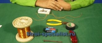
A guide made from a rule, clamps and a piece of polypropylene
Implementation of this design will require:
- construction rule (used for finishing work);
- fastening clamps (the number is determined by the number of attachment points);
- pieces of propylene (thickness is selected depending on the thickness of the entire structure).
A guide made from a rule, clamps and a piece of polypropylene
The manufacturing procedure is as follows:
- If the selected rule has handles, they must be removed. Clamps will be fixed in their place.
- Adapters are cut from a piece of dense propylene. The thickness of the adapters must be greater than the depth of the rule groove.
- The holes remaining from the handles are drilled through along with polypropylene adapters.
- The resulting structure is fixed to the processed bar.
- The finished tire is glued with soft tapes. This allows you to avoid the formation of chips in the workpiece at the time of completion of the cut.
It will ensure quality work. The use of a ready-made building rule requires periodic adjustments to its location. Fastening should be done at a close distance from the cutting line. This allows you to guide the circular saw blade exactly along the intended line.
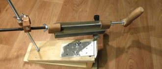
Shafts with a cylindrical cross-section
The cylindrical design makes it possible to maintain balance along the entire length, preventing sagging elements due to the weight of the tenoning carriage. This type of guide is also called linear support shafts. They have precise fixation along the mechanism body thanks to threaded holes. Such guides allow you to move carriages with large weights without sagging.
Disadvantages associated with cylindrical machine tool shafts:
- Short period of operation.
- Significant backlash of rods.
If in linear bearings they interact equally with the loads of different guide vectors, then on shafts with a cylindrical cross-section the tenoning carriage is not so stable.
This is a consequence of the closed sleeve surface, which the tenoning carriage does not have. Therefore, it is necessary to take into account the fact that the CNC hardware will function less stably than a similar machine using ordinary round rail movers.
Modern cylindrical rails are produced by both well-known companies and small artisans. This affects the cost of the device and its technical components. It happens that carriages and rails from one manufacturer do not meet general standards.