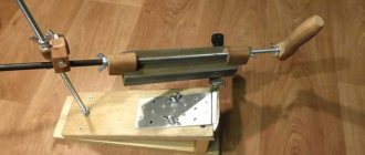
Focusing the light flux into a beam
When creating a laser installation and using a diode removed from a DVD-RW drive, you need to understand that the emitted light will be similar to a standard LED.
LED glow
But we need a laser beam. To make it, you need to use a collimator - a special lens. With its help, the light flux will be focused into a beam. An excellent solution would be to use a lens taken from an old laser pointer in the device. By installing it using nuts and springs, it will be possible to more accurately focus the laser (its approach and distance). The lens can also be attached to the laser diode using epoxy glue or double-sided tape. Due to the fact that it is not always possible to find a powerful diode, in this situation it is recommended to use the 808nm model.
Getting the green ray
Using a crystal of a certain color, you can produce a laser beam of green, yellow, red and blue.
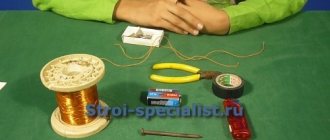
Required parts and materials:
- Arduino Nano(with USB cable)
- 2x DVD drive stepper mechanism
- 2 x A4988 Stepper Motor Driver Modules(or GRBL Shield)
- 250mW laser with adjustable lens(or higher)
- 12V 2Amp minimum power supply
- 1x IRFZ44N N-CHANNEL Mosfet
- 1x 10k resistor
- Resistor 1x 47 Ohm
- 1x voltage regulator LM7805(with heatsink)
- Blank PCB
- Male and Female heads
- 2.5mm JST XH-Style
- 2-pin connector
- 1x 1000uF 16V capacitor jumper cables
- 8x small neodymium magnets (which I salvaged from the DVD lens mechanism)
- 1x 2-pin plug in terminal block screw connector
- Transport tape (100 mm)
- Super glue
- 6x M3x12 screws
- 8x M2x5 screws
- Laser safety glasses.
You will need two DVD drive mechanisms, one for the X axis and one for the Y axis. Using a small Phillips head screwdriver, remove all the screws and the disconnected stepper motor, slide rails, and pusher. Stepper motors are a 4-pin, two-pole stepper motor.
The small size and low cost of the DVD motor means that you should not expect a high resolution motor. This is ensured by the lead screw. Also, not all such motors do 20 steps/24 rev, which is also a common specification. You just need to test your engine to see what it can do.
Disassembling the drive
This process must be performed with extreme caution. If handled carelessly, you can not only damage the device, but also harm your eyes.
The fact is that the laser can blind for some time and negatively affect visual acuity. Therefore, follow all the steps below slowly:
- Open the drive tray (the place where the disc is inserted).
- Turn the device over and unscrew the 4 screws located in the corners.
- Remove the cover.
- Turn the DVD drive over again.
- Remove the aluminum cover.
- Unscrew 2 screws under it.
- Disconnect the cables connecting the drive to the chassis (the one that moves the tray).
- On the chassis, unscrew the only screw on one side and three on the reverse.
- Carefully disassemble the product and remove the board with optical lenses and diodes.
- Remove the protection without making much effort (it looks like a small corner that needs to be turned).
- A diode will be detected.
- The “legs” of the diode (the place where it is attached) must be wrapped with wire - this is a kind of protection against static electricity.
- Using pliers, remove the diode.
- Use a small knife to pry up the diode and carefully remove it from the mount.
First build option
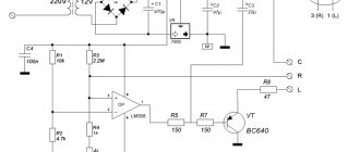
In this situation, it is necessary to use the following scheme for assembling a device based on a laser diode removed from the DVD-RW drive.
Assembly diagram
The disadvantage of this scheme is the presence of a situation where the battery voltage sags at the time of discharge, which causes a linear drop in the laser brightness level. To assemble a laser system according to the above diagram, you need not only a diode, but also capacitors with any voltage (from 3V). In the diagram they are marked with the icon C1 and C2. The capacity of the first capacitor should be 0.1 µF, and the second - 100 µF. They will protect the diode from static electricity and also ensure a smooth transition of processes.
Once the capacitors have been connected to the laser light source, the wire can be removed from the lead. When connected to a diode, one of the terminals on the housing will supply a minus. At the same time, the second conclusion will be a plus, and the third one will not apply. The location of the pluses is shown quite well in the second diagram, which will be described below. It is worth knowing that a plus is supplied to the body of some diodes (for example, 808nm LED). Dual models are characterized by the presence of a middle terminal for the common negative (G), and an outer terminal - C for powering DVD, CD, D. Such a circuit can be powered from a mobile battery or 3 AA batteries.
In this case, the current can also have different values. For example, at the appropriate write speeds of a DVD-RW drive, the laser diode can have the following values of parameters such as power and current:
- at speed 16, the power will be 200 mW, and the current will be 250-260 mA;
- at speed 18, the power will be 200 mW, and the current will be 300-350 mA;
- at speed 20, the power will be 270 mW, and the current will be 400-450 mA;
- at speed 22, the power will be 300 mW, and the current will be 450-500 mA;
- at speed 24 the power will be 300mW and the current will be 450-500mA.
Popular articles Easter chicken with eggs
Infrared diode
The infrared diode of the CD-RW drive will have a power of 100-200 mW. For comparison, violet in BLU-RAY RW is from 60 to 150 mW, and in non-recording models -15 mW. Before assembling this circuit, when using a DVD drive laser diode, you need to find out what resistance is required for resistor R1. To do this, you can use the formula R1=(Uin.-Ufall.)/I, in which:
- Uin. – voltage coming from the battery;
- Upd. is the voltage drop that the diode receives. The red diode should have approximately U drop. equal to 3 V. This voltage is suitable for a low-power non-writing DVD drive. For infrared diode Upad. will be approximately 1.9 V, and for violet or blue - 5.5 V and 4-4.4 V, respectively;
- I is the current strength. It can be found out from a special table.
When assembling a laser, many experts recommend using resistors with a higher resistance than what was obtained in the calculations. This will protect the semiconductor from excessive current. Using a multimeter, you can further reduce the resistance.
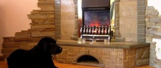
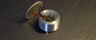
Design and principle of operation
The main element of the engraver is a semiconductor laser. It emits a focused and very bright beam of light that burns through the material being processed. By adjusting the radiation power, you can change the depth and speed of burning.
The laser diode is based on a semiconductor crystal, on top and bottom of which there are P and N regions. Electrodes are connected to them, through which current is supplied. Between these regions there is a P-N junction.
Compared to a regular laser diode, it looks like a giant: its crystal can be examined in detail with the naked eye.
The values can be deciphered as follows:
- P (positive) area.
- P - N junction.
- N (negative) area.
The ends of the crystal are polished to perfection, so it works as an optical resonator.
Electrons, flowing from a positively charged region to a negative one, excite photons in the P-N junction. Reflecting from the walls of the crystal, each photon generates two similar ones, which, in turn, also divide, and so on ad infinitum. The chain reaction occurring in a semiconductor laser crystal is called the pumping process. The more energy supplied to the crystal, the more it is pumped into the laser beam. In theory, you can saturate it indefinitely, but in practice everything is different. During operation, the diode heats up and must be cooled. If you constantly increase the power supplied to the crystal, sooner or later there will come a time when the cooling system can no longer cope with heat removal and the diode will burn out.
The power of laser diodes usually does not exceed 50 Watts. Above this value, it becomes difficult to make an effective cooling system, so high-power diodes are extremely expensive to produce.
There are semiconductor lasers with 10 or more kilowatts, but they are all composite. Their optical resonator is pumped by low-power diodes, the number of which can reach several hundred.
Compound lasers are not used in engravers because their power is too high.
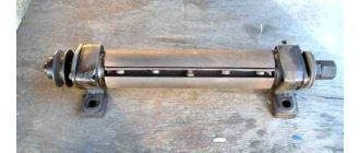
Let's talk about the player
To remove the laser diode taken from the DVD-RW drive, you need to carefully disassemble the device. To do this, you need to understand drive devices. It is placed in a special metal heat-removing housing, which is additionally placed in another metal base. It depends on you whether it is worth removing the device from such a housing or not.
Note! When disassembling a DVD-RW device, you should not take out the loose discs.
DVD-RW drive
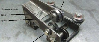
You can also leave the radiator in the case and remove the base. This affects the quality of the heat sink, which is necessary for our laser installation. Some experts argue that when the LED supplies a non-pulse current, the created heat sink will not be enough for the carriage. This statement will be correct for certain drive models, as well as if it is necessary to obtain maximum power. DVD-RW has two laser diodes built into it. Of these, one is infrared and is used for recording and playing CDs. And the second one is red and is used for playing and recording DVDs. As you can see, if you wish, you can make two lasers with your own hands.
Note! The BD-RE drive model has as many as three diodes built in. But modern models of this type of device use dual LEDs installed on one chip.
In such assemblies, you cannot simultaneously connect infrared and red diodes if the current is large.