The broaching machine is designed for the cleanest possible processing of both the internal part and the external surface of parts of any shape. There are a variety of metalworking devices that stand out from each other by certain technological features, the most basic of which is considered to be their direct purpose.
This point assumes:
- machines with internal broaching option;
- machines for external broaching.
One of the most popular in this family are broaching machines with an internal broaching system. Among all the variety, the most popular is deservedly considered a broaching machine with a vertical broaching system, which is used for processing both external and internal parts of a wide variety of parts. The next sign indicating the difference between metal finishing machines is the nature of the working movement and its direction.
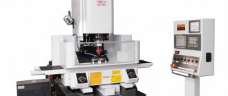
Variant of the appearance of a broaching machine
According to their own properties, all machines belong to one of the following types:
- with horizontal pulling system;
- with a vertical pulling system;
- a device with a linear conveyor movement, the basis of which is considered to be continuity of action;
- a machine that has the option of moving both the broach and the workpiece in a circle;
- a machine that has the ability to use a variety of workpiece movements and broaching simultaneously, and in a variety of combinations.
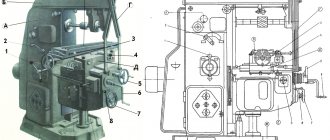
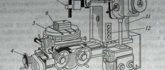
7B56 Location of components of a broaching machine
Photo of horizontal broaching machine 7B56
7B56 main components of a broaching machine
- electrical equipment
- slave cylinder
- work skids
- Remote Control
- cooling device
- support roller
- auxiliary cartridge
- auxiliary skid
- side stand
- locking and unlocking mechanism
- auxiliary cylinder
- working chuck
- work skids
- mechanism for regulating the movement of the machine
- coolant tank
- pumping unit
The main frame is used to accommodate the main parts of the machine: the working cylinder and the working slide, the alignment of which is ensured by bed strips welded inside the frame along its entire length. In the front part of the frame, the frame is closed by a massive base plate, in which a precise hole is made, strictly coaxial with the working cylinder of the machine. This hole is used to install the machine support plate. A slide is provided near the base plate, through which chips with coolant fall into a receiving box located next to the coolant tank. At the front of the main frame, there is a support roller mechanism at the bottom. Its purpose is to support the broach as its rear shank exits the auxiliary chuck. Support is provided until the end of the return stroke of the working slide, when the rear broach shank again enters the auxiliary chuck. The mechanism provides regulation using a spring device for working with broaches of different diameters.
The working slide connects the working cylinder rod with the working chuck. To install the working chuck, they are provided with an adapter sleeve with a conical mounting hole. The design of the working slide allows the load to be transferred directly from the hydraulic cylinder rod to the working chuck using a special coupling and coupler (Fig. 68). The working slides of manufactured horizontal broaching machines move along one flat and one V-shaped bed guide, which increases the geometric accuracy of the machine. The slides are equipped with screwed guide bars that allow compensation for wear in the guides. There is a follower at the bottom of the slide to lower the support roller in the main bed when the work slide approaches the base plate.
The mechanism for regulating the movement of the machine is mounted in the upper part of the main frame. It is made in the form of two rollers, the angular rotation of which turns on and off the limit switches that control the operation of the machine’s hydraulic system. These switches are located outside the main frame in a special housing. By adjusting the position of the cams attached to the rollers, the required values of the working and slow strokes are ensured, as well as the value of the slow stroke and the extreme position of the working slide at the end of the return stroke. The rotation of the cams occurs under the influence of a copier mounted on the working slide.
The attached frame is designed for mounting mechanisms that provide supply and removal of broach. The inlet and outlet movements are communicated simultaneously to the support roller 6 (see Fig. 67) and the auxiliary slide 8 from the auxiliary cylinder 11. At the end of the broach supply, when the support roller is lowered into the opening of the attached frame, the locking and unlocking mechanism 10 ensures the release of the auxiliary slide from the mechanism inlet and outlet. This allows the auxiliary slide to accompany the broach until the end of the cut, which becomes possible due to the fact that the support roller 6 is recessed. At the end of the return stroke, the auxiliary slides are again rigidly connected to the inlet and outlet mechanism using a locking and unlocking mechanism. After this, the withdrawal of the broach begins, at the beginning of which the supporting roller rises and becomes the support of the broach. Its rear shank is fixed in an auxiliary chuck.
When broaching with assisted broaching, the machine mod. 7B56 operates in full half-cycle mode. The interaction of the considered machine mechanisms is reflected in Table. 21. When working in a simple half-cycle mode, the mechanisms located in the attached frame are excluded from operation. The sequence of actions is completely preserved. The simple half-cycle mode is usually used when working with small broaches, for example, keyway ones.
The adjustment dimensions that determine the capabilities of the machine in terms of the broaching length and the length at which tool tracking is provided are shown in Fig. 68.
General classification
The classification of metal-cutting machines is carried out according to various factors. These are divisions by weight, dimensions, type, accuracy class, degree of automation, and versatility. We need to talk about each of their groups in more detail.
Classification by type
There are 9 types of installations based on the type of equipment:
- Lathes. They occupy approximately 30% of the total mass of metal-cutting devices. The workpiece is clamped in a special clamp. The cutting process begins after installing the cutters, which remove a layer of metal under the influence of rotation.
- Boring, drilling units. They occupy 20% of the total mass of machines. The parts are fixed on the work table. Cutting occurs due to the rotation of the spindle with a drill clamped in the chuck.
- Grinding, grinding, polishing machines. They occupy 20% of the total mass of metal cutting installations. Metal cutting occurs due to the rotation of the abrasive material, which comes into contact with the working surface. The processing speed depends on the size of the abrasive.
- Devices for physical and chemical cutting of workpieces. Least common equipment.
- Devices for processing threads and teeth. Occupies 6% of the mass. Used for threading, manufacturing, and sharpening gears.
- Slotting, broaching, planing machines. They occupy 4% of the mass of metal-cutting equipment.
- Milling machines. They occupy 15% of the total mass. Processing of metal workpieces occurs due to the rotation of cutters of different shapes.
- Split installations. Used to separate reinforcement, profiles, corners.
- Machines for performing various operations related to cutting.
Classification by versatility
A separate division of metal-cutting machines is based on their versatility. There are two groups:
- Narrow profile installations. Used to perform one specific technological operation.
- Universal units. They are large-sized structures that are designed to perform various technological operations.
Classification by degree of accuracy
In terms of accuracy, metal-cutting machines come in several types, each of which has its own marking:
- Increased - denoted by the letter P.
- Normal - designation N.
- High - indicated by the letter B.
- Particularly high - designation A.
- The highest accuracy is indicated by the letter C.
To use units marked B, A, C, you need to prepare the room in advance. It must maintain a constant temperature and humidity level.
Classification by degree of automation
Based on the degree of automation, the following types of metal-cutting machines are distinguished:
- Manual models. The worker needs to clean, prepare workpieces, set up all moving elements independently, and coordinate the work process.
- Semi-automatic machines. The worker needs to change parts independently, turn on and off moving mechanisms.
- Automatic machines are units that process workpieces independently. Used in mass production.
- CNC equipment. The operator sets the required algorithm through the program. The moving mechanisms work independently, select optimal modes, load and unload parts.
CNC machines are gradually replacing other machines due to high processing accuracy and increased productivity.
Metal cutting automatic machine
Classification by weight
Industrial metal-cutting machines are divided by weight. Highlight:
- Lightweight - structures weigh up to 1000 kg.
- Medium - weight starts from 1 ton and ends at 10 tons.
- Large - weight from 16 to 30 tons.
- Heavy - weight from 30 to 100 tons.
- Super heavy - structures weigh more than 100 tons.
Designations are indicated in the technical data sheet.
7B55 Horizontal broaching machine for internal broaching. Purpose and scope
The horizontal broaching machine 7B55 has been produced since 1981. The machine was discontinued and was replaced with a more advanced model. Currently, the plant produces more advanced horizontal broaching machines and semi-automatic machines: 7A523, 7A534, 7A545, 7555.
The horizontal broaching machine 7B55 is designed for processing, by broaching, pre-processed or rough through holes of various geometric shapes and sizes of parts made of ferrous and non-ferrous metals and alloys. Using special devices, you can process external surfaces.
The 7B55 broaching machine is distinguished by high productivity and high processing accuracy.
The most effective use of the 7B55 machine is in mass and large-scale production. The ease of readjustment of the machine allows it to be used in small-scale and individual production.
Design features of the horizontal broaching machine 7B55:
By agreement with the customer, the machine is supplied both in a universal version and with special fixtures and tools for processing one or more specific parts.
When equipped with automated devices for feeding and removing workpieces, the machine can operate in an automatic cycle, as well as be built into automatic lines.
The machine drive is hydraulic, the speed control of the working and reverse strokes is stepless.
The removal and supply of the broach to the working chuck, as well as the cutting process, are mechanized.
For ease of maintenance, the machine is equipped with a mechanism for adjusting the stroke length of the working slide, centralized forced lubrication of the guides, signaling of dullness of the broach using an electric contact pressure gauge, and oil filtration in the hydraulic system.
Starting and safety electrical equipment is located in a separate electrical cabinet, which facilitates its maintenance and increases its service life.
The use of contactless track switches, low-current electrical control equipment and electrical control equipment and DC electromagnets ensures high reliability of electrical equipment.
The increased rigidity and vibration resistance of the machine design allows it to work in the entire range of operating speeds and traction forces, while maintaining a high class of surface cleanliness and broaching resistance.
- Hydraulic drive
- Stepless speed control of working and reverse strokes
- Mechanized feed in and out of the broach over the entire cutting length
- Centralized forced lubrication of rubbing surfaces
- Hydraulic oil filtration
- Signaling using an electric contact pressure gauge about the dullness of the cutting tool
- High reliability of electrical equipment due to the use of contactless track switches, low-current electrical control equipment and DC electromagnets
- Possibility of integrating the machine into an automatic line
On special order for an additional fee, the machine is equipped with a supporting prism, which allows you to compensate for the weight of the workpiece and simplify the process of its installation relative to the broaching axis, and a load lifter for installing and removing heavy workpieces and broaches.
At the request of the customer, the machine can be manufactured in one of two versions: with or without an attached bed (model 7B55U), and can also be supplied both in a universal version and with a special device and tool for processing one or more specific parts.
The machine is certified according to the first quality category.
Roughness of processed surfaces Rz20—Ra 0.63 μm (V5—V8).
Machine accuracy class N according to GOST 8-77.
The corrected sound power level LpA does not exceed 108 dBA.
Design organization - Minsk Special Design Moscow Bureau of Broaching Machines.
Main technical characteristics of the horizontal broaching machine 7B55
Design organization - Minsk Special Design Moscow Bureau of Broaching Machines.
Minsk Machine Tool Plant named after S.M. Kirov. Start of mass production in 1973.
- Nominal traction force – 98 kN (10,000 kgf)
- The longest working stroke of the slide is 1600 mm
- The diameter of the hole in the faceplate is 100 mm
- Working speed – 1.5÷11.5 m/min
- Main movement drive electric motor power – 17 kW
- Machine weight – 6.9 t
Types of spline broaches and areas of their application
Splined broach, as mentioned above, is used for processing internal surfaces on which there are splined elements. Such tools, depending on the number and type of cutters with which they are equipped, can be:
- involute;
- sharp-slotted;
- 6-spline;
- 8-spline;
- 10-spline.
The broach for slotted holes TsL-2408-4333-8Х42Х46 is made of R6M5 steel
Splined broaching, depending on its type, can be produced according to one of the following regulatory documents:
- with an involute type profile: 50038-92 – two-pass combined; 50035-92, 28050-89 – conventional combined type; 25158-82, 25159-82 – for processing holes with a cross-section of 15–90 mm; 25157-82 – for processing holes with a cross-section of 12–14 mm; 25160-82 – for processing holes with a cross-section of 45–90 mm;
- with a straight-sided profile: 25971-83, 25972-83 – for processing eight-spline holes; 25969-83, 25970-83 – for processing six-spline holes; 24822-81, 24823-81 – for ten-spline holes;
- with screw-on shank: P 50035-92, 50036-92, 50037-92, 28048-89, 28049-89, etc.
In some cases, when it is not possible to select a standard tool, the manufacture of broaches can be carried out according to specially developed design documentation.
Using spline-type broaches, you can effectively perform the following technological operations:
- cutting keyways and splines;
- processing of rifled weapon barrels;
- calibration of internal holes of various types;
- production of aircraft engine turbine elements;
- stretching external surfaces with complex configurations.
Review of the metalworking machine model 7B56
Since 1981, a broaching machine model 7B56 began to be produced for the industrial area. They are processed on a broaching machine of this model using the method of correct horizontal broaching through the through holes of the part. The processing itself is rough, and the composition of the processed parts is ferrous and non-ferrous metals, as well as various alloys.
If additional tools were used, it became possible to carry out external processing of parts. This device had high processing accuracy and sufficiently high productivity to be used on an industrial scale. Below is a description of the design features and characteristics of the broaching horizontal machine 7B56.
Its features include:
- smooth adjustment of the speed of both working and return movement;
- hydraulic drive of the existing broaching mechanism;
- good quality of the machined surface, associated with increased resistance of the machine to vibrations. This condition was achieved due to an increased level of rigidity and allows for uniform operation over the entire range of traction forces at any speed;
- automatic supply of lubricant to all rubbing surfaces, as well as high-quality filtration of oil in the hydraulic system;
- triggering of the existing alarm when the cutting tool becomes dull;
- the presence of contactless track switches, as well as DC electromagnets, makes it possible to achieve a high degree of reliability and safety of all electrical equipment;
- the possibility of upgrading this machine for subsequent installation on an automatic line;
- the processing accuracy of the horizontal broaching machine 7B56 belongs to the normal class (H);
- the total length of the working stroke of the existing horizontal slide is 160 cm;
- the speed of movement of the broaching mechanism varies in the range of 1.5 – 11.5 meters per minute;
- hydraulic traction force is 200 kN;
- the presence of a powerful 30 kilowatt electric motor that drives the main drive.
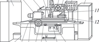
Hydraulic diagram of broaching machine 7B56
Manufacturers and models
The Gigant enterprise offers a wide range of models. Its product range includes modifications of broaching machines 7A523, 7A612, 7555, etc. Models differ in processing speed, traction force, power, dimensions and other characteristics. Among foreign manufacturers, the company HOFFMANN Raumtechnik has won trust, which is engaged not only in the development of classic models with vertical and horizontal processing lines. In its family you can find specialized broaching machines. The RAWX-M series models, for example, are designed specifically for finishing grooves and gear joints. The RASA-M modification is distinguished by the presence of four tracks designed for processing spherical grooves of various couplings. For specialized needs, you can look for a suitable model in the family of the Yaroslavl manufacturer Forst Technologie, which is famous for its careful approach to the manufacture of broaching cutting elements of a special design.
Elements and geometry of the cutting part of the broaches
The round broach (Fig. 21) consists of the following elements. Locking part 1 (shank) serves to secure the broach in the chuck of the machine's traction device; neck 2 – connecting surface. The guide cone 3 and the front guide part 4 serve to center the workpiece at the beginning of cutting. The cutting part 5 consists of cutting teeth, the height or width of which increases by the height of the layer being cut, and serves to cut off the main portion of the allowance. To facilitate the formation of chips on the cutting teeth, chip-breaking grooves are made in a checkerboard pattern.
The calibrating part 6 is designed to give the treated surface the final shape, the required accuracy and roughness. It consists of calibrating teeth, the shape and dimensions of which correspond to the shape and dimensions of the machined surface. The rear guide part 7 is necessary to support the broach as it exits the machined hole. Rough and finishing teeth of broaches have different geometries.
The rough teeth (Fig. 21, a, section A–A) are sharpened. The clearance angle for internal broaches is 3°, for external broaches – 3–8º. The rake angle is selected depending on the properties of the material being processed within 10–20°. The pitch between the teeth is selected from the requirement that at least three teeth operate simultaneously. Lift per tooth – 0.06–0.3 mm/tooth.
A
b c
Rice. 21. Broaches: a, b – round; 1 – locking part; 2 – neck; 3 – guide cone; 4, 7 – front and rear guide parts, respectively; 5 – cutting part (cutting teeth); 6 – calibrating part (calibrating or finishing teeth); f – ribbon; Sz – rise per tooth; t – pitch between teeth; α, γ – main rear and front angles, respectively; c – broach for making an internal keyway
Finishing teeth (Fig. 21, a, section B–B) are made with a strip equal to 0.02–0.3 mm. The rake angle is selected depending on the properties of the material being processed within the range of 0–15°. A zero rake angle is usually assigned for profile broaches, which makes it possible not to lose the geometric accuracy of the teeth during regrinding. The pitch between the teeth t is selected from the requirement that only one tooth participate in the work. Lift per tooth – 0.015–0.03 mm/tooth.
Classification, types of broaches and their application.
1. As intended
broaches are divided into two groups.
For treating internal surfaces
(holes):
— round — for processing round holes;
- spline - for processing spline holes;
— keyed – for processing keyways;
— faceted – for multifaceted surfaces;
— broaches for processing helical grooves.
For treating external surfaces
various profiles:
— broaches for processing gears;
— broaches for pulling cylindrical surfaces of shafts;
— broaches for external splines of various profiles on shafts;
— broaches for producing dovetail-shaped grooves, T-slots, herringbone profiles, etc.
2. By design
broaches can be:
3. In the direction of the blades
Regarding the speed of the main movement, they are distinguished:
— broaches with ring and screw teeth. These are broaches for internal pulling.
- broaches with straight and inclined teeth. These are broaches for external broaching, flat and keyed.
4. According to the material of the cutting part
distinguish:
- broaches made of tool steel,
5. According to the applied cutting pattern
broaches are distinguished from:
— profile (or ordinary);
— progressive (or group);
— generator (or step) cutting schemes.
6. According to the number of broaches in the set
broaches are distinguished:
Specifications
One of the disadvantages of such machines is the dimensions. As a rule, this is an elongated platform in which the workpiece is placed. Dimensional characteristics on average are about 2 m in length, 0.5 m in width and 1.5 m in height. However, the configurations can be different - accordingly, the sizes also differ. The weight is about 500 kg, so before installation it would be a good idea to provide a reliable foundation. From a productivity point of view, the speed of drawing, that is, processing, is also important. For example, a broaching machine from the Flexible Connections enterprise in modification SGP.12.35 provides a working speed of 220 mm/min. In other words, in one minute the equipment can make a cut on an internal surface more than 20 cm long. Here it is also worth considering the maximum processing area, since in most cases, performing the same cutting lines in two approaches is technologically unacceptable. The average length of a single service varies from 4 to 5 m.
Optional equipment
The design of the machine may require the use of additional equipment: machine vices, clamping bars. A transverse key is often used with a flat broach lock; a bracket and a wedge are used for a cylindrical lock. Modern broaching machines involve the use of electronic equipment to control the production process, but this equipment is included in the design of the machine.
A used broaching machine can cost from RUB 2,500,000. For more complex designs the price increases. The maximum price of a broaching machine is 10,000,000 rubles.
Design and principle of operation
The mechanical part of planing machines consists of the following elements:
- cast iron or steel frame - the main part of the structure that bears the main loads, used to accommodate the assembly with the cutting tool and the work table;
- working surface - designed for placing workpieces and fastening them;
- guides—necessary for moving the slider or working surface;
- slider - performs translational movements when processing workpieces;
- a cutter used for cutting metal;
- caliper - fixes the cutter at a certain angle;
- gearbox - used to change the rotation speed of the spindle with a fixed workpiece;
- vice for fixing parts during processing.
The design also includes electrical components: motor, controls, monitoring sensors, protection systems. To cool the mechanical elements, a system for supplying lubricants and coolants is used. All machine components are located inside a steel or cast iron body.
The operating principle is based on direct contact of the cutting tool with the workpiece. Machining occurs when the workpiece moves or rotates relative to the cutter.
Processing the part (Photo: Instagram / khuevgen)
Features of operation
Operating personnel are required to place the workpiece in the working niche of the equipment. Next, after launch, the actual processing process begins. A key feature of the functioning of such machines is the fact that the working elements in the form of broaches do not remove chips immediately after cutting, but push them out only after the final exit from the body of the workpiece. Therefore, the range of operator tasks is also expanded due to the need to monitor how correctly machining is performed. On vertical-type broaching machines, the risks of deviations and incorrect cut lines are not so high, since bending of a long workpiece due to its own weight is eliminated.
Part processing technology
The description of the processing process on broaching machines is as follows: the part to be finished is mounted on a standard table faceplate for operation in compliance with all safety measures. A broaching device is passed through the hole of this part, which is mounted specifically in the traction chuck. After turning on the start button, oil is supplied inside the cylinder, which presses on the rod, forcing the broaching component to move.
At the time when the moving carriage, with its own stop element, runs into a specialized stop for rearrangement, the limit switch is triggered, due to which the working stroke of the carriage is stopped. At another stage of operation, its movement in the opposite direction will occur.
At the last stage, the operator activates the button for turning on the idle feed, after which it will return to its initial position and at this point the operating cycle of the device will be considered completed.
Modern horizontal broaching machine
The specific method of fixing the broaching element in the chuck depends on the model of the broaching machine, which can be not only ordinary and quick-release, but also fully automated.
Due to the fact that there is a specialized thread on the shank of the machine body, the chuck is connected to the working carriage.
Great Encyclopedia of Oil and Gas
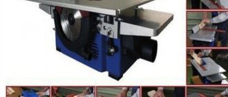
| Multi-cutter attachment for a planer. |
Vertical-broaching machines, compared to horizontal-broaching machines, occupy a smaller area, are more convenient in securing broaches, but have a high workplace due to the need to place the broach under the working position. Vertical machines are used in mass production for processing light and medium-weight parts. The machines are produced for external and internal broaching. Their nominal traction force is 50 - 200 kN, working speed is 0 5 - 14 m / min, carriage stroke length is 600 - 1600 mm.
Vertical broaching machines occupy a significantly smaller area than horizontal ones. It is more convenient to install workpieces for processing on these machines; removal of the part can occur automatically; After broaching, there is no need to return the broach to its original position, since it is automatically secured either to the upper end or to the lower end.
| Horizontal broaching machine model 7510M. |
Vertical broaching machines are used mainly for external broaching.
| General view of a horizontal broaching mill. |
Vertical broaching machines are used mainly for external broaching. The operating principle of such machines is similar to horizontal broaching machines. To increase labor productivity in mass production, continuous broaching machines are widely used.
Vertical broaching machines for external broaching allow the following traction forces: mod.
Vertical broaching machines for internal broaching must be equipped with a guard that protects workers from injury if the broach falls out of the return mechanism chuck. The design of the fence must prevent hands from entering the area between the broach and the fence.
Vertical broaching machines for internal broaching must have a guard to protect workers from injury if the broach falls out of the return mechanism chuck.
According to the hydraulic drive scheme, vertical broaching machines differ little from horizontal broaching machines and have similar control units. All hydraulic drive calculations for reciprocating motion given in the planing machines section are generally applicable to broaching machines.
Machines used for broaching are divided into horizontal, vertical and continuous. Vertical broaching machines occupy a significantly smaller area than horizontal ones. It is more convenient to install workpieces for processing on these machines; removal of the workpiece can occur automatically; After broaching, there is no need to return the broach to its original position, since it is automatically secured either to the upper end or to the lower end. Vertical broaching machines are produced in one- and two-position versions; they can broach one or two workpieces at the same time.
When performing a broaching operation, the cutting speed is regulated by the kinematics of the broaching machines and the drive power of the broaching machines. Small vertical broaching machines have a tractive force of up to 100 kN and can reach cutting speeds of up to 25 m/min. In practice, the maximum service life of broaches is usually achieved at a cutting speed v 5 m/min. However, in order to increase productivity, the cutting speed can be increased to 10 m/min.
When performing a broaching operation, the cutting speed is regulated by the kinematic capabilities and drive power of broaching machines. Small vertical broaching machines have a tractive force of up to 100 kN and can reach cutting speeds of up to 25 m/min. In practice, the maximum service life of broaches is usually achieved at a cutting speed v 5 m/min. However, in order to increase productivity, the cutting speed can be increased to 10 m/min.
Pages: 1 2
Vertical broach
The working principle of a vertical broaching machine for internal broaching is based on the fact that the main movement is performed rectilinearly in the vertical direction by the cutting element of the machine, while the workpiece of the future part remains stationary. In addition, when using the screw broaching method on such devices, which is one of the types of internal broaching, additional rotation is also given to both the workpiece itself and the cutting element.
Vertical broaching machine
A vertical internal broaching machine has virtually the same operating rules as a horizontal one, but with certain advantages, which include the following:
- during operation, machines of a similar class as such do not have the possibility of sagging and distortion of the axis of the broaching element;
- on a machine of a similar class it is not difficult to install additional broaches in the event of modernization;
- A vertical broaching machine occupies a relatively small area for operation. This is due to the fact that its entire operating cycle occurs strictly in the vertical direction.
- Machines with vertical broaching not only take up less usable space during operation, but are also much more convenient than their horizontal “colleagues”. Machines of this type are very often used in production, where global processing of light and medium-heavy parts is performed.
The best geyser coffee makers of 2021 - 12 TOP rating of the best
Scheme for setting up a vertical broaching machine
Vertical broaching machines also come in both external and internal broaching types. All such options are subject to the following criteria:
- traction force, it all depends on the machine model, can range from 50 to 200 kN;
- the maximum maximum amount by which the working carriage moves is in the range from 60 to 160 centimeters;
- the speed of the broach during the working cycle can vary from 0.5 to 14 meters per minute.
It must be said that both vertical and horizontal broaching machines use a semi-automatic operating principle in their process. As an exception, there can only be broaching machines with software, the entire manufacturing process of which is simplified as much as possible and has the highest speed.
An additional feature that distinguishes one metal processing machine from another is the number of working carriages available, since there are machines not only with one, but also with several. The next characteristic feature is position. The simplest is considered to be a single-position design, but the most effective are machines with a multi-position operating principle, since they contain factory table devices with a rotary system in their own technological equipment.
Safety requirements
When working on broaching machines, it is necessary to strictly observe personal safety measures, which have general principles for all metalworking equipment.
There is a specialized document containing a set of conditions and requirements for broaching machines installed in production. So, for example, safety when cutting on metalworking machines with vertical broaching is ensured by installing a special protective element that protects the operator from injury in cases where the heavy broaching mechanism falls out of the chuck.
During the period of work on horizontal broaching machines, it is mandatory to install a protective folding screen with glass to monitor the process throughout the entire exit area of the broaching element.
It is worth noting that for safety reasons, it is strictly forbidden to install or remove the broach while the metalworking machine is operating. In the case of using a broach whose weight is more than eight kilograms, the use of a special lift is a mandatory requirement.
Horizontal broach
A horizontal broaching machine is used in any situation where there is a need to process the internal or external part of a part, the main movement of which will occur in the linear horizontal direction. Correct movement is performed using specialized broaches with different profiles.
Horizontal broaching machine
The operating cycle of such a machine is performed only in a strictly horizontal direction. During operation, removal of chips from the entire area of the part to be finished is carried out due to the uniform movement of the teeth over the entire length of the existing broach. In order for the overall process to be completely automatic and non-hazardous, it makes sense to use a machine for processing and cutting metal with a CNC installed.
Machines with vertical broaching are designed for precision machining of the surfaces of parts of various shapes, made of both ferrous and non-ferrous metals. The vertical broaching machine is used mainly in a wide variety of industrial sectors - for example, in the automotive industry - for the purpose of mass production of parts of all possible shapes.
Scheme for setting up a horizontal broaching machine