Physical principles of high frequency heating
To form solder joints, non-contact heating methods in the form of concentrated radiation fluxes of electromagnetic fields in a wide frequency range are currently widely used.
A special place in this range is occupied by high-frequency (HF) electromagnetic fields, the effect of which energy on soldered parts and solder is manifested in the form of high-performance non-contact heating to soldering temperature using eddy currents induced in the metal. The heating rate can be increased up to 10 times compared to convective sources; the heating zone is localized within an area determined by the design of the inductor. A high heating rate with HF currents is achieved by appropriate selection of the current frequency. Since the density of RF currents over the cross section of the part is distributed unevenly, but increases towards the surface due to the surface effect, the depth of their penetration into the metal is determined as: where ρ is the electrical resistivity of the metal, μ is the magnetic permeability of the metal, f is the frequency. Heating by an electromagnetic field of average frequency 66–150 kHz with an intensity of 1–100 MW/m2, at which the ratio of penetration depth to part thickness h is within the range δ/h 10 for steel 0.7–0.8, for copper - 0, 5.
When soldering metal cases of microelectronic devices containing a substrate or board placed inside with elements sensitive to the electric component of the field, the energy of electromagnetic interference should be much less than the degradation energy of IC elements, which is 10–15 μJ [4]. At a depth of 4δ, the field strength will be weakened by 100 times compared to the surface and an order of magnitude lower than the interference strength leading to degradation of internal elements. The upper limit of the current frequency follows from the requirement for the maximum value of the thermal heating efficiency. Thus, the choice of frequency when soldering microelectronic devices in packaged versions must be carried out according to the condition [5]:
where δ is the depth of penetration of high-frequency frequencies into the metal, h is the thickness of the housing.
The frequency range of RF heating, taking into account relation (9), is determined as follows:
These conditions correspond to heating by the energy of HF electromagnetic oscillations in the range of 440–2000 kHz. With increasing heating frequency, heat generation is localized and the temperature effect on the soldered product is reduced. A further increase in the locality and selectivity of heating by HF currents is achieved with the help of magnetic cores made of ferrite, installed near the heated areas. The effect of a powerful electromagnetic field on molten solder causes intense mixing due to eddy currents and ponderomotive forces, which improves the spreading of solder. Exposure to the energy of electromagnetic vibrations makes it possible not only to carry out high-performance non-contact heating of parts and solder using HF eddy currents induced in them, but also to activate the solder and improve its spreading over the soldered surfaces. The quality of soldered joints in RF soldering processes depends on the heating rate of parts and solder, selectivity and locality of heating, uniformity and controllability of heating over time and across the cross-section of the parts being soldered.
The heating rate by HF currents is proportional to the power released in the part:
where Veff is the effective voltage on the inductor, cosφ is the heating power factor, RH is the electrical resistance of the heating zone.
The electrical resistance of the heating zone is defined as:
where lH is the perimeter of the heating zone, H is the width of the heating zone.
Thus, HF heating is characterized by the greatest efficiency for metals with high resistivity and magnetic permeability (for example, nickel alloys), which decreases in inverse proportion to the square root of the oscillation frequency. Reducing the oscillation frequency increases the electrodynamic effect of mixing the molten solder.
Heating adjustment
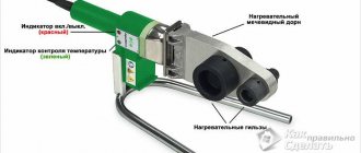
The core of an induction soldering iron is made of copper (not a magnetic material), and the back of it is coated with a ferromagnetic material (an alloy of iron and nickel). The front part serves as a sting, the core itself is called a cartridge.
The heating of the copper tip is adjusted as follows:
We can say that automatic temperature control occurs, and with high accuracy.
The maximum heating of an induction soldering iron depends on the properties of the magnetic alloy and core. This control is called smart heat.
You can change the temperature for specific soldering conditions by installing a temperature sensor that is connected to the station control unit, or by changing the cartridges (core with tip) that are inserted into the handle of the induction soldering iron.
The first option is cheaper than the second, so today it is used not only by professionals. But the second method is more accurate and reliable.
Technology and equipment for RF structural soldering
RF structural soldering is widely used in tool production, large-scale production of capacitors, relay equipment, tubular electric heaters, switching devices and waveguide paths. Switching devices: contactors, circuit breakers, etc., both low and high voltage, contain contacts made of metals and alloys with special properties based on silver, copper, nickel, tungsten and other elements.
Contacts are made in the form of plates, which are attached, as a rule, by soldering to a copper contact holder, thus forming a contact unit with it. Soldering of contact assemblies is carried out mainly with hard silver-containing solders using HF heating. The large range and complexity of the contact holder configuration makes it difficult to design heating systems, select the frequency and power of power supplies, and develop inductors. Based on the requirements of unification (at one station it is necessary to solder parts with a thickness of approximately 0.5 to 5 mm), generators with an operating frequency of 66 or 440 kHz are selected. The areas of application of HF structural and assembly soldering are shown in Fig. 2.
Soldering is carried out on a round metal table, where devices for fastening the tail parts of the contact holders are fixedly mounted. The table is given discrete rotation, that is, a quick turn one step - the angle between adjacent devices - and holding in each position. Machine productivity is up to 900 rations per hour. The operations of loading a powder mixture of solder with flux, as well as contact plates, are mechanized. The soldered units arrive in the heating zone, covering three to six positions, in an assembled state.
For the design of the machine, two feed-through inductors are used. Heating of components in which the soldering zone of the contact holder is not shielded by other areas is carried out in inductors with a one-sided arrangement of inductive conductors. Contact holders of several sizes and different configurations were heated in them. At a frequency of 66 kHz, uniform heating of the surfaces to be soldered to 700...800 °C was achieved in 10–16 s, regardless of the thickness of the contact holder [6].
To prevent excessive heating of the metal table, a water-cooled copper screen is used. The configurations of some contact holders that are subject to soldering cannot be heated in inductors with a one-sided arrangement of inductive conductors.
To heat such units, feed-through inductors with double-sided arrangement of inductive conductors have been developed (Fig. 3). In them, the soldering zone is heated mainly due to thermal conductivity, and therefore there is a danger of overheating of the contact holder section up to melting. Therefore, it is necessary to increase the heating time, but this reduces productivity, or to increase the length of the inductor in order to heat more parts in it at the same time. This leads to an increase in power consumption due to increased energy losses and operation of the generator in suboptimal mode.
Stable quality of soldered assemblies was achieved by dosing energy according to the heating time under stabilized operating conditions of the generator. However, when soldering some standard sizes of contact assemblies, defects from 10 to 50% occur, mainly due to unsoldered solder or leakage of solder, which is a consequence of the variability of the temperature of the workpieces.
When dosing energy over time, the reasons for the variation in heating temperature can be: insufficient stabilization of the lamp generator modes (generators of the VChI-100/0.066 type have anode voltage stabilization of 1% with fluctuations in the network up to 10%, however, the supply voltage may differ from the nominal by 15– 20%, and this factor is difficult to eliminate); unstable position of the soldered parts relative to the inductor, determined by the variation in shape and size (weight of parts, accuracy of mechanisms and clamping devices, amount of backlash; in this case, the temperature variation can be reduced by increasing the heating time); the variability of the physical properties (electrical conductivity, heat capacity, etc.) of soldered parts is a very significant factor.
In order to avoid using a separate inductor for each size during mechanized induction soldering of round-shaped parts - spherical bushings, rings, etc., a gas-cooled inductor with interchangeable parts was developed [7]. Such an inductor for RF soldering in a gas environment, in comparison with a conventional ring-shaped inductor, is more versatile, since all components are made, assembled and soldered from copper. To this is added the necessary water cooling and shielding gas.
RF assembly soldering
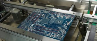
Manual soldering of pin contacts of connectors to printed circuit boards has always been labor-intensive, insufficiently repeatable connections and a high probability of damage to printed conductors with a heated soldering iron. Induction heating of contacts made of magnetic material - nickel - made it possible to implement group soldering with high productivity.
When 24 contacts are placed in the electromagnetic field of an induction coil, powered by a generator with a frequency of 450 kHz and a power of 5 kW, each contact experiences individual heating, causing the solder to melt on the contact pads of the printed circuit board. This allows you to obtain good quality connections with a controlled dose of solder. This method is also convenient for unsoldering connectors and removing them from the board. To improve the quality of contact connections when RF soldering of multi-pin connectors into metallized MPP holes, the surface of the board facing the inductor is cooled with a chemically neutral liquid, for example an alcohol-glycerin mixture. The liquid, enveloping the soldering areas, protects the solder from oxidation and reduces the heating of the board. When heated from the VChI4-10 generator in the mode: Ia = 1.5–2 A, Ic = 0.25–0.35 A, the soldering time is no more than 15–20 s, and the heating of the board does not exceed 60...70 °C.
Improving the quality of solder joints and improving the wetting of soldered surfaces is achieved by modulating HF oscillations in the range of 100–1000 kHz with a low-frequency signal of 18–66 kHz from an external source with a modulation depth of 20–100% [8] (Fig. 7).
The circuit contains a source of LF oscillations (1), an HF generator (2), an inductor (3), soldered parts (frame 4 and substrate 5 with thick film metallization), a control device (6) and a pyrometer (7). Non-contact input of ultrasonic vibrations during HF heating promotes the formation of high-quality soldered joints due to the complete filling of the seams in the joints.
When using RF heating, it is important to quickly regulate the heating rate so that the soldered parts and solder simultaneously reach the soldering temperature [9]. HF voltage is applied to the inductor and the product is heated (section I in Fig. 8). After melting the solder (point a), the intensity of RF heating is reduced depending on the required temperature regime of the soldering process (section II), which avoids overheating of the solder and also reduces heating of the product. Then the HF voltage is turned off and the product is cooled (point b, section III).
To solder the frame (1) to the microassembly board (2), a device has been developed (Fig. 9) containing a clamp (3), an inductor (5), a cassette (4) and a heat-insulating board (6). The location of the inductor under the board prevents accidental touching of it during the soldering process; the movement of the cassette can be automated using a transport device. The lower location of the inductor has a flatter heating characteristic, which eliminates overheating of the LSI, as well as touching the inductor, which increases operational safety.
Induction heating has been successfully used for reflow bonding of lead-free solder balls with a diameter of 0.76 mm to board pads coated with 10 µm nickel and 0.05 µm gold. The balls were manually placed on the substrate, and then, together with the substrate, were heated in the center of the inductor turn (Fig. 10). The current frequency was 300 kHz, the current value varied from 11 to 29 A. The solder reflow temperature was achieved at an inductor current of 17 A for 12 s and a current of 27 A for 3 s [9]. Solder balls were then used to attach the BGA packaged LSIs to the board pads. Using the physical laws of activation by EM field energy, it is possible to provide high-performance non-contact heating of the IE using eddy currents, activate the molten solder and improve its wetting and spreading over the soldered surfaces and thereby improve the quality of contact connections.
Source
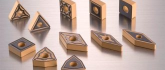
Soldering of carbide plates. Instructions
General provisions.
These instructions apply to soldering cutters on HDTV installations: VCHI-25, VChG-60, LP3-2-67M and other similar ones.
Preparation of carbide plates and cutter holder bodies for soldering.
- All operations for pre-processing carbide plates should be carried out before cleaning the supporting surfaces.
- Sharp corners on hard alloy plates and pressing defects: swelling, chipping (GOST 2209-90) must be removed by chamfering or cleaning.
- Plates that are warped must be ground.
- The surfaces to be soldered must be cleaned and freed from oxides by grinding on a diamond wheel. The gap between cleaning and soldering should not exceed 2…3 days.
- Cracks, chips and blockages on hard alloy plates are not allowed.
- The surfaces of cutter holders subjected to soldering should not have nicks, cracks, burrs or blockages that would interfere with the tight fit of the carbide plates. Casting pores, cavities and underfills in the soldering area are not allowed. Toolholders with such defects are rejected.
- Carbide inserts and holder bodies must be free of rust, oxides, oils and other contaminants.
- When performing soldering with compensating spacers, the holder sockets must be lowered by 0.3...0.8 mm.
Quality control of preparation of carbide inserts and cutter holders.
- The cleanliness of the soldered surfaces of hard alloy plates must be within class 6...8 (1.6v...0.4v).
- The cleanliness of the soldered surfaces of the cutter holder must be within class 4…6 (6.3v…1.6v).
- All plates supplied for soldering must comply with GOST 25393-90, GOST 25426-90, GOST 2209-90, GOST 17163-90, GOST 20312-90, GOST 22771-90, GOST 9391-80 in terms of microstructure and have a durability coefficient of at least specified in the technical specifications of the drawing.
- The permissible gap between the plate and the body is 0.08...0.12 mm.
- Deviation from straightness should not exceed ± 0.05 mm.
- Permissible warping of plates <0.04 mm.
- The maximum overhang of carbide inserts should not exceed 2.0 mm.
- Control of the mutual fit of the carbide plates and the grooves of the holders is carried out on 1...3% of the tool units from the batch, but not less than 5 pieces. Inspection visually or using a probe.
Preparing solder and flux for soldering.
- For soldering cutters, use: solder ANMts-06-4-2 TU 48-21-87-80 of the following chemical composition: Cu – 64.5%, Ni – 4.5%, Mn – 2.0%, Zn – the rest. Solder melting temperature is 1035...1060? C. Soldering temperature 1100...1180? C.
- brass solder MNMts 68-4-2 TU 48-08-476-71 of the following chemical composition: Cu – base, Ni – 3...4%, Mn – 1.5...2.5%, Al – 0.5...0, 6%. The melting temperature of solder is 930...960? C. Soldering temperature 990...1060? C.
Tool soldering.
- Preparation for soldering. Parts should be supplied for soldering according to the accompanying documents, executed by inspection, indicating the tool code, its quantity, grade of material, TT drawing and cutter sketch indicating the position of the carbide plate relative to the holder body. Before soldering, prepare the thermal carts for operation, the sand temperature should be within 150...300? C, the sand layer should be at least 100...150 mm. Monitor the temperature of the sand in thermal carts with a thermometer, immersion depth of at least 40 mm. The temperature of the sand in the thermocouple is recorded using an XA thermocouple.
- The selection of an inductor is carried out under the condition of installing a soldered cutter with a gap between the inductor and the holder within 5...15 mm, no more, or under the condition of installing two cutters with a gap between the cutters of no more than 0.5 mm, between the inductor and the holder of 5...15 mm, no more. Install the rotary table at the slot inductor. Select the current strength and voltage using test cutters. The heating time at a given current and voltage is adjusted by the table rotation speed and the gap between the inductor and the cutter, which should be within 5...15 mm. During the passage of the cutter in the inductor, the solder must be melted.
- The pyrometrist prepares the KSP-3 device for use.
- Adjustment of the HDTV installation by circuit voltage, anode and grid current is carried out during test soldering of 2...5 cutters from the batch (code) of cutters. The received data is recorded in a journal with a record of codes and dates of soldering with the signature of the controller.
- If necessary, combine soldering with hardening with compressed air. Open the air system, blow out the supply hoses for 5...10 minutes to remove moisture, set the required air flow using the PC5 flow meter. Write the data to the log. Temper the support part of the cutter holder in a special trough with running water, adjust the stand for the cutter so that the water level does not reach the carbide plate 4...8 mm. Select the immersion depth to obtain the required hardness.
- On the thermogram of the KSP-3 device, record the test soldering with the code written down, indicating the name of the thermist and controller. The entries in the journal and on the thermograph must match.
- Before soldering, ensure the quality of fit of the holders and carbide plates in accordance with paragraph 3. Blow off the holders and carbide plates with sand, rinse in hot water at T = 80...90 C and dry in the open air or under a stream of compressed air.
- Cool cutters that are not subject to hardening after soldering for 10...40 seconds in air, depending on the cross-section of the holder, and lower them into a heat transfer cart with sand. Maintain the temperature in the thermal cart within 150...300 C while filling it with cutters. After filling, turn off the cart. Cool the cutters in the thermal cart to a temperature of 80 C in accordance with the readings of the device, then remove them and cool them in air to ambient temperature.
Hydrosandblasting
- All cutters that have undergone heat treatment should be sent to the hydrosandblasting department.
- Each cutter must be blown individually by hand on a soft lining (rubber mat) to prevent breakage of the carbide plates.
- Rinse the blown incisors in hot water at a temperature of at least 80 C and dip into the GZh1 preservative solution.
Removing excess solder.
- Solder deposits present on soldered cutters can be removed mechanically (by cleaning).
Quality control of cutters after soldering and heat treatment.
- Quality control of the soldered tool is carried out after blowing.
- Adjustment and soldering of test cutters should be carried out on 2...5 pieces, depending on the size of the batch and their compliance with the TT drawing.
- There should be no excess solder or flux on the surface of the cutters in the form of sagging or smudges. It is allowed to tin the body plates with a thin uniform layer of solder no more than 0.5 mm.
- The solder layer under the carbide plate should be within 0.05...0.35 mm. In the seam around the perimeter and corners, isolated places without soldering (pores) are allowed. On the side supporting surfaces of the carbide insert, the total length of the gaps should not exceed 50% of the solder seam. Breaks in the solder seam between the supporting surfaces of the carbide insert and the holder should not exceed 10% of the visible length of the solder seam on through and scoring cutters and 5% on slotting and parting cutters. GOST 5686-61 (ST SEV 1165-78). Solder breaks under the main cutting edge are not allowed.
- The quality control of the soldered seam should be carried out visually on 2…5 broken cutters (beat off the carbide plate before opening the solder) depending on the batch size. It is allowed to beat a carbide plate on an arbitrarily selected cutter during the batch soldering process. Soldering is suitable if there are defects (oxidation, flux residues and unsoldered joints) not exceeding 10% of the total area of the soldered seam.
- Check the absence of chips and cracks in the hard alloy using a magnifying glass with 4…10x magnification.
- Control of the hardness of the holder in accordance with the technical specifications of the drawing should be carried out at a distance of 3...10 mm from the soldered seam, depending on the design and configuration that allows for control; hardness measurements should be carried out on cut samples with a ground surface.
- Permissible displacement of the carbide insert relative to the supporting part of the holder is ±0.5 mm.
- Final quality control is carried out after sharpening using the LUM-1OV method in accordance with clause 8.4. Cracks and chips on carbide inserts and holders are not allowed. The assessment of soldering defects is carried out visually by the appearance of the soldered seam on broken cutters (see paragraph 8.5.). The passage of cutters with defects is carried out with the permission of the workshop quality commission with an entry in the journal. After sharpening and detection of defects on the LYUM-1OV, resoldering of the cutters is carried out according to the accompanying document with the permission of the workshop commission with an entry in the journal and a spacer on the holder with the distinctive mark “P”. The permissible number of re-solderings is no more than 2 times.
The cutters used for quality control should be written off according to the report
HDTV induction soldering
High-frequency induction soldering or soldering using high-frequency currents is a very effective technology since the use of modern high-frequency transistor generators, specialized machines and equipment allows for local heating of the required area, and not the entire part. Induction heating allows you to quickly and uniformly heat a local area of a part, which is a clear advantage of HDTV soldering.
High-frequency induction soldering finds its application in the following areas: high-frequency high-frequency soldering with high-temperature solders of electrical machine windings (hydrogen generator stators, squirrel-cage motor rotor windings), carbide plates for tools, group simultaneous high-frequency induction soldering of more than a hundred plates in a vacuum with precision heating of complex-shaped parts, soldering capacitor terminals, etc.
The developed equipment and experience in soldering work allow us to design hand tools, installations for induction soldering of similar products and unique installations for precision high-frequency soldering of complex large-sized parts. Mobile equipment can be used to fulfill orders with travel to the Customer for soldering the windings of electrical machines.
High-frequency induction soldering of high-frequency carbide plates to steel holders is widely used in the manufacture of metal-cutting tools (cutters, drills, cutters), drill bits, soil rippers, etc. A new area of application for brazing carbide plates is surface hardening of the working surface of turbine blades. These problems can be successfully and efficiently solved using induction soldering. HDTV induction soldering is an energy-saving technology. The high specific powers that are realized during induction heating make it possible to quickly heat a local zone to a soldering temperature of 600 - 1200 °C, spending minimal energy on the process compared to the traditional gas heating method.
Wood and metal processing
The essence of the high-frequency soldering process
The essence of the high-frequency soldering process
According to the method of heating products when soldering with hard solders, all existing soldering processes can be classified into four main types: gas, electric, immersion in a heated environment or solder and soldering in ovens.
When gas soldering, heating is carried out by the flame of a gas burner. Both conventional welding torches and specially designed torches can be used. The most common method is single-torch soldering with sequential heating of the soldered seam with gradual addition of solder as the seam warms up.
Electric soldering includes arc soldering using an electric arc between two carbon electrodes, contact soldering, which is similar in heating to spot or roller welding, and high-frequency soldering using induction heating. With the last two types of soldering, electrical energy is converted into heat directly in the part itself, heating those areas in which soldering should occur.
There are two types of immersion soldering: in one case, the parts to be heated are immersed in a hot medium, most often these are molten salts, in the other - in molten solder, where they are heated and soldered. Soldering in furnaces includes soldering of parts using both resistance furnaces with metal or silitov heaters, and gas-flame furnaces. Electric soldering furnaces can be specially designed for heating in a reducing environment or in a vacuum.
All of the above soldering methods are very different from each other. The first two types are based on the use of local heating of the product at the junction, the others require heating of the entire product during soldering. Already based on this, we can draw a conclusion about which methods require more energy, large production areas and which are more productive and economical, despite the fact that in some cases they require more complex and expensive equipment.
Soldering is the process of joining metal parts in a heated state, in which the gap between them is filled with a more easily melted molten metal or alloy - solder, which holds them together when cooled. When soldering, molten solder, penetrating into the gaps, creates a metallic bond between the soldered parts of the product, which are in a solid state.
Soldering differs from fusion welding in that it leaves the base metal in a solid state.
Some authors believe that soldering is a type of welding process.
Some analogy can be drawn between metal soldering and gluing. A thin layer of glue is applied to the parts to be glued, after which they are connected. The glue wets the surface of the seam, penetrates the pores and, when hardened, gives a strong connection. An essential feature of soldering, as opposed to gluing, is the diffusion of solder into the base metal.
To obtain a strong connection when soldering, it is necessary that the parts to be soldered are well fitted to each other, so that the liquid solder well wets the surface of the solid metal being soldered and ensures good adhesion, so that the solder and the soldered metal can form strong alloys and have the ability to mutually penetrate each other.
What prevents solder from properly wetting the metal surface during soldering?
If the surfaces to be soldered have any insulating layer (grease, paint, scale, oxide film, etc.), then their wettability with solder will be poor and the soldering will be weak. If wettability is poor, the solder will not be absorbed into the gap and spread, but will tend to take the form of a drop, like a drop of water on a greasy surface.
Solder properties such as wettability, spreadability and fluidity largely determine the quality of soldering. In addition, when choosing a solder, it should be taken into account that the wettability of metals and alloys in relation to each other is completely different. For example, if molten pure silver perfectly wets copper and its alloys, then it does not wet steel at all.
Analyzing all existing soldering methods, it is easy to come to the conclusion that good soldering will be achieved if the metal is heated to a temperature slightly higher than the melting point of the solder, and the solder falls on a surface that has not had time to oxidize or has been cleaned during heating, regardless of how heating was achieved in this way.
For good wettability of the surface of the soldered metal with solder, conditions are necessary that are created in two ways: by reducing the oxidation of the metal and removing oxides through fluxes, or by creating conditions for the reduction of oxides and eliminating the possibility of their occurrence during the heating process by isolating the product from the oxidizing environment.
There are soldering methods in which oxidation of the metal surface during heating and cooling can be completely avoided by isolating the soldered parts from the atmosphere. These include mainly soldering in furnaces with a reducing atmosphere or vacuum. Hydrogen and dissociated ammonia are most often used as reducing media.
The hydrogen atmosphere protects metals from oxidation and reduces oxides, so this process does not require fluxes. In furnaces with a reducing atmosphere, steel parts are most often soldered with copper.
Since during high-frequency soldering the heating of the product is caused by currents induced in it, and the heating intensity in a certain zone of the product largely determines the conditions for obtaining good soldering, soldering depends mainly on the concentration of the high-frequency magnetic field in this zone.
Mastering the process of high-frequency soldering means basically learning how to control the high-frequency electromagnetic field, learning to concentrate it only in the desired zone, where in a short period of time it is necessary to achieve uniform heating of the metal to high temperatures.
High frequency soldering differs significantly from other soldering methods. Heat here is not transferred to the workpiece from the environment, but arises in it itself as a result of the action of induced currents. The tool that transmits high-frequency energy into the metal being soldered is an inductor. It is a coil or spiral of several turns of a copper tube, cooled by water during operation, through which a high-frequency current flows. In this case, an alternating magnetic field is created around the turns. The parts prepared for soldering are placed in an inductor, where they are penetrated by an alternating magnetic field. An alternating magnetic field induces an electromotive force, under the influence of which currents arise in the metal, heating the parts to the required temperature.
There is no reason to assume that high-frequency currents have any specific effect on the soldering process, however, it is quite obvious that rapid heating of the metal and intense movement of molten solder under the influence of electromagnetic field forces activate the flux, improve surface wettability and force the solder to penetrate the gaps more vigorously . All this has a positive effect on the quality of soldering.
To obtain uniform results when high-frequency soldering of identical parts, it is very important that the heating conditions are strictly constant. The quality of soldering is affected not only by the final heating temperature of the junction, but also by the duration of heating. With a very short heating time, less than 5-10 seconds, the diffusion of solder into the base metal may be insufficient; with prolonged heating, excessive oxidation of the solder and soldered metal will occur with a significant unproductive expansion of the heating zone. In both cases, incorrect heating mode leads to deterioration in soldering quality.
Manufacturing instructions
Blueprints
Figure 1. Electrical circuit of an induction heater
Figure 2. Device.
Figure 3. Schematic of a simple induction heater
To make a stove you will need the following materials and tools:
- soldering iron;
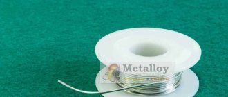
- solder;
- textolite board.
- mini drill.
- radioelements.
- thermal paste.
- chemical reagents for etching the board.
Additional materials and their features:
- To make a coil that will emit the alternating magnetic field necessary for heating, it is necessary to prepare a piece of copper tube with a diameter of 8 mm and a length of 800 mm.
- Powerful power transistors are the most expensive part of a homemade induction installation. To install the frequency generator circuit, you need to prepare 2 such elements. Transistors of the following brands are suitable for these purposes: IRFP-150; IRFP-260; IRFP-460. When manufacturing the circuit, 2 identical of the listed field-effect transistors are used.
- To manufacture an oscillating circuit, you will need ceramic capacitors with a capacity of 0.1 mF and an operating voltage of 1600 V. In order for high-power alternating current to form in the coil, 7 such capacitors will be required.
- When operating such an induction device , field-effect transistors will become very hot and if aluminum alloy radiators are not attached to them, then after just a few seconds of operation at maximum power, these elements will fail. Transistors should be placed on heat sinks through a thin layer of thermal paste, otherwise the effectiveness of such cooling will be minimal.
- Diodes used in an induction heater must be ultra-fast. The most suitable diodes for this circuit are: MUR-460; UF-4007; HER – 307.
- Resistors used in circuit 3: 10 kOhm with a power of 0.25 W - 2 pcs. and 440 Ohm power - 2 W. Zener diodes: 2 pcs. with an operating voltage of 15 V. The power of the zener diodes must be at least 2 W. A choke for connecting to the power terminals of the coil is used with induction.
- To power the entire device you will need a power supply with a power of up to 500 W. and voltage 12 - 40 V. This device can be powered from a car battery, but it will not be possible to obtain the highest power readings at this voltage.
The manufacturing process of the electronic generator and coil itself takes a little time and is carried out in the following sequence:
- from a copper pipe . To make a spiral, the copper tube should be screwed onto a rod with a flat surface with a diameter of 4 cm. The spiral should have 7 turns, which should not touch. Fastening rings are soldered to the 2 ends of the tube for connection to the transistor radiators.
- The printed circuit board is made according to the diagram. If it is possible to install polypropylene capacitors, then due to the fact that such elements have minimal losses and stable operation at large amplitudes of voltage fluctuations, the device will operate much more stable. The capacitors in the circuit are installed in parallel to form an oscillating circuit with a copper coil.
- Heating of the metal occurs inside the coil after the circuit is connected to the power supply or battery. When heating the metal, it is necessary to ensure that there is no short circuit in the spring windings. If you touch 2 turns of the coil at the same time with heated metal, the transistors will fail instantly.